HAL Id: hal-01419586
https://hal.sorbonne-universite.fr/hal-01419586
Submitted on 19 Dec 2016HAL is a multi-disciplinary open access archive for the deposit and dissemination of sci-entific research documents, whether they are pub-lished or not. The documents may come from teaching and research institutions in France or abroad, or from public or private research centers.
L’archive ouverte pluridisciplinaire HAL, est destinée au dépôt et à la diffusion de documents scientifiques de niveau recherche, publiés ou non, émanant des établissements d’enseignement et de recherche français ou étrangers, des laboratoires publics ou privés.
Two-Dimensional Colloidal Nanocrystals
Michel Nasilowski, Benoit Mahler, Emmanuel Lhuillier, Sandrine Ithurria,
Benoit Dubertret
To cite this version:
Michel Nasilowski, Benoit Mahler, Emmanuel Lhuillier, Sandrine Ithurria, Benoit Dubertret. Two-Dimensional Colloidal Nanocrystals. Chemical Reviews, American Chemical Society, 2016, 116 (18), pp.10934 - 10982. �10.1021/acs.chemrev.6b00164�. �hal-01419586�
2D Colloidal Nanocrystals
Michel Nasilowski1,Benoit Mahler2, Emmanuel Lhuillier3, Sandrine Ithurria1, Benoit Dubertret1*
1 Laboratoire de Physique et d’Étude des Matériaux, PSL Research University, CNRS UMR 8213, Sorbonne Universités UPMC Univ Paris 06, ESPCI ParisTech, 10 rue Vauquelin, 75005
Paris, France
2 Institut Lumière-Matière, CNRS UMR5306, Université Lyon 1, Université de Lyon, 69622 Villeurbanne CEDEX, France,
3 Institut des Nanosciences de Paris, UPMC-UMR 7588 CNRS, 4 place Jussieu, boîte courrier 840, 75252 Paris cedex 05, France
Abstract: In this paper, we review recent progresses on colloidal growth of 2D nanocrystals.
We identify four main sources of anisotropy which lead to the formation of plate- and sheet-like colloidal nanomaterials. Defect induced anisotropy is a growth method which relies on the presence of topological defects at the nanoscale to induce 2D shapes objects. Such a method is particularly important in the growth of metallic nanoobjects. Another way to induce anisotropy is based on ligand engineering. The availability of some nanocrystal facets can be tuned by selectively covering the surface with ligands of tunable thickness. Cadmium chalcogenides nanoplatelets (NPLs) strongly rely on this method which offers atomic control in the thinner direction, down to a few monolayers. 2D objects can also be obtained by post or in situ self-assembly of nanocrystals. This growth method differs from the previous ones in the sense that the elementary objects are not molecular precursors, and is a common method for lead chalcogenide compounds. Finally, anisotropy may simply rely on the lattice anisotropy itself as it is common for rod-like nanocrystals. Colloidally grown Transition Metal DiChalcogenides (TMDC) in particular result from such process. We also present hybrid syntheses which combine several of the previously described methods and other paths, such as cation exchange, which expand the range of available materials. Finally, we discuss in which sense 2D-objects differ from 0D nanocrystals and review some of their applications in optoelectronics, including lasing and photodetection, and biology.
Keywords: 2D, beyond graphene, nanoplates, colloidal growth, anisotropy,
Table of contents
1. Introduction ... 4
2. Defect induced anisotropy ... 16
2.1. Symmetry breaking during nucleation ... 16
2.2. Twin defects ... 17
2.3. Anisotropic growth due to twin defects ... 18
2.3.1. Singly-twinned nanoparticles ... 18
2.3.2. Multiply-twinned nanoparticles ... 19
2.4. Inducement of twin defects and oxidative etching ... 22
2.5. Kinetic control and selective passivation of nanoplate growth ... 24
3. Ligand engineering ... 28
3.1. Ligand templating ... 28
3.2. The case of zinc-blende cadmium chalcogenides nanoplatelets ... 30
3.3. Thickness tunability ... 32
3.4. Colloidal 2D heterostructures... 37
3.4.1. Core-shell ... 38
3.4.2. Core-crown ... 40
3.5. Alloying and doping: ... 41
3.5.1. Alloying ... 41 3.5.2. Doping ... 42 3.6. Hybrid system ... 43 3.6.1. SiO2 encapsulation ... 43 3.6.2. Metal functionalization ... 44 4. Self-assembly ... 44
4.1. The case of lead chalcogenides self-assembly ... 44
4.2. Colloidal structure with 2-x dimensionality ... 45
5. Colloidal synthesis of chalcogenides with a layered crystalline structure ... 49
5.2. Colloidal synthesis of transition metal dichalcogenides ... 51
5.2.1. Column IVB and VB chalcogenides ... 51
5.2.2. Column VIB chalcogenides, molybdenum and tungsten compounds. ... 55
5.3. Transformations and applications ... 57
5.3.1. Manipulations ... 60
5.3.2. Functionalization ... 61
5.4. IV-VI lamellar chalcogenides... 64
5.5. Tetradymite colloidal compounds ... 66
6. Alternative growths and hybrid materials ... 68
6.1. Light induced methods ... 68
6.2. Cation exchange ... 70
6.3. 2D perovskites ... 72
7. Applications and perspectives ... 75
7.1. Why is 2D special ? ... 76
7.2. Application for light emission ... 77
7.3. Application for photodetection ... 79
7.4. Applications for biology and chemistry ... 82
8. Conclusion ... 85
Acknowledgments ... 86
References ... 87
1. Introduction
Nanocrystals are particles with at least one dimension comprised between 1 and 100 nm. For the last decades, they have been of growing interest as they exhibit unique properties due to their small size. They are often described as artificial atoms, as their sparse density states can be modified tuning their shape, size and composition.1 Indeed, electron confinement in those nanostructures provides the nanocrystals with properties that are much different from their bulk counterparts and can be used to enhance electric, optical or magnetic properties.2 A typical example of the influence of size on the crystal properties are Quantum Dots (QDs) which are nanocrystals made of semiconducting materials. The band-edge energy between
the conduction and the valence band depends directly on their size, which gives their fluorescence wavelength a strong size-dependence. The shape is another parameter of key importance to control the properties of such nanoparticles as the motion of electrons (and therefore holes and plasmons) can be confined in given directions. For example, not only the catalytic activity of metals is enhanced when their size is reduced,3,4 but the selectivity of the catalyzed reactions is also strongly dependent on the exposed facets, and therefore on the shape of the nanocrystals (NCs).5,6 Besides, the surface plasmon resonance (SPR) in Au NCs is mostly dependent on their shape:7 changing the geometry of the nanocrystal changes the energy of the plasmon peak more than the mere increase of the size of the spherical particles. Finally, the size, but also the shape of the nanoparticles (NPs) plays an important role in the cellular uptake.8,9 The need to control the shape of the NPs is therefore strong and the growing interest in shape-controlled syntheses of NCs is confirmed by numerous contributions for different applications such as optics (photodetectors,10,11 lasers,12 fluorescence13–15), electronics,16–18 catalysis,19 biological sensing20 and imaging.21,22 The top-down (chemical or mechanical exfoliation23–26 by ion intercalation, ion exchange, sonication27 or by the “Scotch-tape” method28) as well as the bottom-up approaches have so far been explored to synthesize 2D nanostructures with different techniques used such as physical deposition methods (vapor deposition29, molecular beam epitaxy (MBE)30), lithography,31,32 or wet chemical methods. The latter present the advantage of being relatively cheap, easy to implement and scalable, but the precise control of the size and shape of the synthesized NPs is still challenging. However, in the last decades, numerous groups have improved the wet chemical growth techniques and have intensively studied the growth of anisotropic structures. This review will focus on the solvothermal syntheses protocols and mechanisms used to obtain colloidal metal and semiconductor nanocrystals with a two-dimensional geometry.
The synthesis of nanoparticles using wet chemical methods requires, in general, the same three components: precursors which provide the atoms for the growth of the NP (by thermal decomposition or conversion to more reactive species); ligands which ensure colloidal stability and which have a key role to precisely control the size and shape of the obtained nano-objects ; and the solvent which provides a homogeneous reaction medium in which the precursors are soluble and the final NCs are stable (it is to be noted that the solvent can also act as a source of precursors or ligands33). All these components, depending on their reactivity or their affinity to specific crystal facets provide good tools to control not only the size but also the shape of NCs. Before entering into the details of shape control, we will briefly remind the LaMer theory and introduce the two important steps for the bottom-up colloidal synthesis of NCs: nucleation and growth. After those steps, Ostwald ripening can occur;34 it is generally avoided to preserve a good size monodispersity of the particles.
NCs are produced following a general synthesis scheme: precursors, which provide atoms to build the NCs, decompose or rearrange into monomers and form nuclei during the nucleation step. These nuclei can further grow to form bigger crystals either by continuous deposition of monomers on their surface, by attachment of several nuclei together or by Ostwald ripening. The nucleation-growth theory has been introduced by La Mer in the 50s, adapted from a theory developed by Becker and Döring in the 20s.35,36
Homogeneous nucleation occurs spontaneously and randomly, without the need for a nucleation site. It requires however a solution that is supersaturated in precursors. Heterogeneous nucleation, on the other hand, occurs at a nucleation site, which is a solid phase in contact with the liquid (or vapor) phase containing the precursors. In La Mer’s theory, the so-called nucleation, which is the spontaneous formation of nuclei in the solution, is a homogeneous process, while the growth can be considered as a heterogeneous one, as precursors deposit on a nucleation site in the solution (the already formed nuclei).
The basic idea behind the theory is that a thermodynamic system tends to minimize its Gibbs free energy or increase its enthropy.37 The Gibbs free energy of a spherical cluster can be expressed as follows: ∆𝐺 = −4 3𝜋𝑟 3|∆𝐺 𝑉| + 4𝜋2𝛾 Equation 1
where 𝑟 is the radius, |∆𝐺𝑉| is the difference is the Gibbs free energy per unit volume, and 𝛾 is the surface energy per unit area, i.e. the energy needed to create a surface of unit area. The Gibbs free energy consists of two terms. The first one, negative, expresses a decrease of the Gibbs free energy, and thus a favorable event. In this case, it corresponds to the bonding of a monomer to the cluster. The second term, positive, expresses the unfavorable increase of the energy surface after the bonding of a monomer. The change in the Gibbs free energy due to the formation of a bond between a cluster and a monomer therefore corresponds to a competition between the decrease of the volume energy and the increase of the surface one. Below a certain critical size, corresponding to the critical radius 𝑟𝑐 = 2𝛾 |∆𝐺⁄ 𝑉| (calculated by canceling the derivative of Equation 1), the positive surface energy increase is higher, thus pushing the system towards the dissolution: the growth is unfavorable. Above 𝑟𝑐, the negative volume energy decrease is higher, thus growth is favored.
Figure 1: Evolution of the Gibbs free energy of a cluster versus its size (black curve). The evolution of the two terms in the Gibbs free energy equation is also shown; the volume (or bulk) energy (blue curve) and the surface energy (in red). The critical radius 𝒓𝒄 and the
activation energy ∆𝑮𝒄 are also presented on the figure. Adapted from ref. 37 - Published by The Royal Society of Chemistry.
Figure 1 shows the evolution of the Gibbs free energy of a cluster. The energy barrier ∆𝐺𝑐 corresponds to ∆𝐺 at 𝑟𝑐. Once this energy barrier is overcome and the critical radius reached, stable clusters form in solution: the nuclei. These nuclei can further grow through heterogeneous nucleation.
Indeed, the surface energy necessary for nucleation is lower at phase boundaries, which become so-called nucleation sites. Therefore, once the nuclei are formed, subsequent nucleation occurs preferentially on the present nuclei. However, homogeneous nucleation is still possible, and can occur in the same time as heterogeneous nucleation. The concept of burst nucleation was introduced by Victor La Mer and relies on the separation of nucleation and growth of the nanoparticles. In order to achieve efficient separation, the idea is to produce all the nuclei at the same time, and let the growth happen only later. Figure 2 describes the evolution of the concentration of monomers versus time, showing the mechanism of the burst nucleation: in phase I, either because of a swift injection of precursors or because a critical temperature is reached, the precursors convert into monomers whose concentration increases. The supersaturation is reached at a concentration 𝐶𝑆, however the energy barrier to start nucleation has still to be overcome. In phase II, the saturation keeps increasing to reach a concentration 𝐶𝑚𝑖𝑛 at which the activation energy is overcome: homogeneous nucleation can occur. This nucleation is very fast, hence the name “burst nucleation”. Due to the nucleation, the concentration of monomers drops, decreasing the saturation and therefore ending the nucleation step. In phase III, nucleation has stopped and the remaining monomers will only attach to the existing nuclei to grow the NPs.
Figure 2: Evolution of the monomer concentration vs time according to La Mer's theory of burst nucleation. Adapted from ref. 37 - Published by The Royal Society of Chemistry.
The NP will grow in such a way to reduce its surface energy, which is the limiting parameter, already present in the nucleation step. Historically, in 1874,38 Gibbs suggested that the shape of a crystal is dictated by the minimization of the total surface energy. Therefore, the shape of crystals (and nanocrystals, as it has been shown that the equilibrium shapes of the macroscopic crystals and nanocrystals are the same when they have the same chemical composition39,40) is therefore not dictated by the minimum total surface (which is a sphere), but depends strongly on crystalline facets. The final equilibrium shape will be dominated by the facets with the lowest surface energies. In 1901, Wulff41 assumed that the surface free energy of a crystal depends on the facet’s crystallographic orientation: the shape of the NP is then determined by the crystallographic nature of the expressed facets with low surface energy. In isotropic phases, this turns out to be a sphere, but for NPs which express different facets, the shape may be more complex than the mere spherical shape. An easy construction method that allows to determine the equilibrium shape of NCs has been developed by Wulff and is called the Wulff construction.42 It requires knowing the energy needed to create a surface of unit area in the directions normal to the atomic planes (hkl) (which is the direction of the vector [hkl]) 𝛾ℎ𝑘𝑙. This energy is roughly proportional to the number of broken bonds on a surface: due to smaller distances between atoms on facets with high coordination such as close-packed facets, those facets have less dangling bonds per area unit, lowering the surface energy compared to facets with more dangling bonds. When this energy is known, after choosing a set of axes, one can plot the plane normal to [hkl] at a distance 𝑐 ∙ 𝛾ℎ𝑘𝑙 (where 𝑐 is a constant) of the origin of the axes. The same operation is repeated for all the (hkl) planes, and the geometrical shape lying inside all the plotted lines corresponds to the shape with the minimal total free energy.40,43 Figure 3 presents an example of Wulff construction for an orthorhombic structure, with 𝛾100 = 𝛾110 = 1/2𝛾010, knowing that all other (hkl) planes have much higher surface energies. The equilibrium shape in this conditions is a rod-like prism, that
is indeed found experimentally for some orthorhombic structures such as aragonite CaCO3.44,45
Figure 3: Example of Wulff construction for an orthorhombic structure. The equilibrium shape is shown in grey and is comprised in the lines corresponding to the low energy facets. Adapted from ref. 40 – Belstein J. Nanotechnol.
For a face-centered cubic (fcc) structure, the surface energies can be estimated as follows: 𝛾100 = 4(𝜀 𝑎⁄ 2), 𝛾110 = 4.24(𝜀 𝑎⁄ 2) and 𝛾111 = 3.36(𝜀 𝑎⁄ 2) where 𝜀 is the bond strength and 𝑎 is the lattice constant.2 Thus, the surface energies can be ordered 𝛾
111< 𝛾100 < 𝛾110, showing that the NC should adopt a shape to favor (111) facets. However, not only the surface energy is important, the surface area also needs to be taken into account, and the NC will tend to minimize it too, resulting in truncated octahedrons enclosed by (111) and (100) facets.46–49
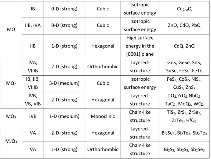
These first examples show that the equilibrium shape of a NC cannot be determined only by the minimization of the surface area as it would always yield spherical-shaped NCs. Due to symmetry reasons and to asymmetric bond strength, some materials prefer growing in one or two dimensions. Their equilibrium shape is therefore nanorods or nanoplates. Table 1 gives examples of preferred thermodynamic shapes for some chalcogenide NCs.
M (metal) Thermodynamic preference (level) Crystal structure Reason Materials Q (=S,
Se, Te) 1-D (strong) Trigonal
Chain-like structure Se, Te M2Q IB 1-D (medium) Hexagonal High surface energy in the (0001) plane Cu2Q
MQ
IB 0-D (strong) Cubic Isotropic
surface energy Cu2−xQ
IIB, IVA 0-D (strong) Cubic Isotropic
surface energy ZnQ, CdQ, PbQ
IIB 1-D (strong) Hexagonal
High surface energy in the (0001) plane CdQ, ZnQ MQ2 IVA,
VIIIB 2-D (strong) Orthorhombic
Layered-structure
GeS, GeSe, SnS, SnSe, FeSe, FeTe IB, IIB,
VIIIB 3-D (medium) Cubic
Isotropic surface energy
FeS2, CoS2, NiS2, CuS2, ZnS2 IVB,
VB, VIB 2-D (strong) Hexagonal
Layered-structure
TiQ2,ZrQ2,NbQ2, TaQ2, MoQ2, WQ2
MQ3 IVB 1-D (medium) Monoclinic Chain-like structure
TiS3, ZrS3, ZrSe3, ZrTe3, HfQ3
M2Q3
VA 2-D (strong) Hexagonal
Layered-structure Bi2Se3, Bi2Te3, Sb2Te3
VA 1-D (strong) Orthorhombic Chain-like
structure Bi2S3, Sb2S3, Sb2Se3
Table 1 : Thermodynamic preferences of chalcogenide nanocrystals. Reproduced from Ref. 50 with permission from The Royal Society of Chemistry.
There are however in the literature numerous examples of nanocrystals whose shape is not their thermodynamic equilibrium shape. For example, FeS2 tend to grow in three dimensions, but two-dimensional FeS2 nanoplates have been reported.51,52 Thus, certain synthesis parameters force the NCs to grow in a non-energetically favored shape and yield two-dimensional structures. What drives this anisotropic growth?
The syntheses of NPs seldom happen in conditions close to the equilibrium. They rather deviate from these conditions and follow driving-forces that favor one shape over the other. Several mechanisms can explain the anisotropic growth of NCs.
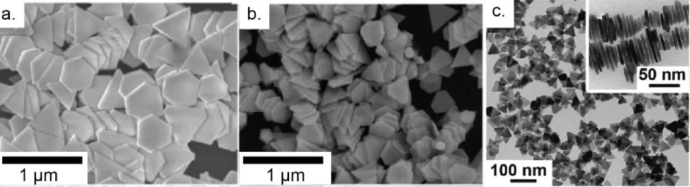
During the nucleation of NCs, not all the nuclei are the same. Some of them might have a specific shape, others might present defects. The initial seed is therefore important in determining the final shape of the NCs as different nuclei will grow differently. Defect induced anisotropy, such as twin plane in fcc metals, has been widely studied and is one of the major driving force for two-dimensional growth, and can yield metal nanoprisms or nanoplates (Figure 4).53–56 This growth mechanism will be developed in part 2.
Figure 4: a. and b. Field Emission Scanning Electron Microscopy images of Au nanoplates with edge lengths of varying size. Adapted with permission from Ah et al. (2005) (ref. 57). Copyright (2005) American Chemical Society. c. Transmission Electron Microscopy (TEM) images of Ag nanoplates, with, in the inset, stacked Ag nanoplates, standing vertically on their edges. Adapted with permission from ref 48. Copyright (2011) American Chemical Society.
Because some nanoparticles have shapes that do not correspond to their thermodynamic equilibrium shapes, kinetic effects have to be taken into account. Indeed, depending on the growth rate of the nanoparticles, or on their ligands, the nanoparticles can be blocked in a local energy minimum. The nanoparticle nucleation takes place on time scales ranging from a fraction of a millisecond to a few milliseconds. The reorganization of atoms may occur on longer time ranges, not giving enough time for the structure to find the absolute energy minimum, thus being blocked in a metastable configuration that can give the NP its final shape.58
When the growth rate of nanoparticles is high, the fast addition of precursors does not favor any facets, exhibiting high-energy facets such as {221} facets in fcc metals.59,60 On the other hand, when the growth rate is slowed down (lower temperature, slower reduction rate…), the growth is faster on high-energy planes, therefore more energetically-favored facets are expressed, such as low-indexes {111} planes in fcc metals (Figure 5).60
Figure 5: Shape evolution of a nanoparticle during growth. Rapid addition to high-energy facets y (relative to x-edges) results in the elongation of the x, low-energy edges. From ref. 2. Copyright 2009 by John Wiley & Sons, Inc. Reprinted by permission of John Wiley & Sons, Inc.
This growth sequence can be dramatically changed because of the influence of ligands. Indeed, they can cap specific facets, slowing the growth of the passivated facets compared to the other ones. Because the growth in some crystallographic directions is hindered, rod- or plate-like symmetries can be obtained. This effect is called chemical poisoning.
Many factors influence the chemical poisoning effect. First, because the passivation of some facets is the primary driving force for anisotropic growth, the ligands will play a crucial role in determining which facets will grow. Their affinity to the atomic species at the surface of the nanoparticle will help a better or worse passivation. For CdSe nanoparticles, for example, a strong ligand such as trioctylphosphine (TOP), or trioctylphosphine oxide (TOPO), shows such strong affinity to surface cadmium ions that it reduces the energy difference between the different facets, annihilating the chemical poisoning effect: the growth rate of all the facets becomes very similar, leading to isotropic, spherical CdSe NPs.61 The nature of the ligand is of course very important: it can be inorganic62 or organic,61,63,64 and a small change in its nature can yield totally different results.65 Controlling the chemical poisoning induced by ligands can lead to different shapes using the same material and crystal structure. For example, wurtzite CdS or CdSe/CdS nanocrystals can be synthetized with rod66, tetrapod67 or plate like shapes68,69 depending on the synthesis conditions and the use of phosphonic acid ligands which hinder the nanocrystals growth perpendicular to the wurtzite c axis, leading to the formation of rod-shaped nanocrystals.Another important characteristic of ligands is their propensity to form close-packed layers: it is called the soft-templating effect, developed in part 3. While electrostatic forces bind the ligands to the surface of the NPs (eg. negatively charged acids with positively charged ions), the organic chains of the ligands, which ensure the colloidal stability, can form a stable assembly that decrease the energy of the facets and therefore hinder the growth in this direction, yielding nanoplatelets (see Figure 6), or increase the steric repulsion between NPs through their bulky and rigid chains, decreasing the probability of random attachment between several NPs (see part on Oriented Attachment).63,64,70,71
Another important factor in the ligand-mediated shape control is the temperature of the growth reaction. Not only can the temperature play a role in the kinetic control of the NP growth by lowering the differences in the energies of the facets, but it also acts on the formation of the ligand assemblies. Indeed, low temperature growth will enhance the subtle energy differences between the facets, and subsequently the corresponding growth speeds differences. Besides, the close-packed layers of surfactants can form under a certain temperature, above which they decompose and cannot play their role as a soft template anymore.64,72,73
Figure 6: A and B. 2D CdSe nanoparticles of different lateral size. C. Scheme of the CdSe two-dimensional nanoparticle. The ligands are fatty acids that attach with their negatively charged acid function to the positively charged Cd ions at the surface of the NP. Their organic backbone form a fatty-acid layer that acts as a soft template hindering the growth in the direction of the passivated planes. Scale bar is 50 nm. Adapted with permission from ref. 64. Copyright (2011) American Chemical Society.
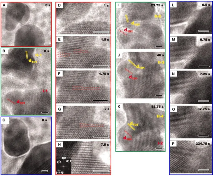
Once the nuclei are present in solution, they can grow through the addition of precursors or self-assemble in solution to form new, larger crystals. This mechanism is developed in part 4. In 1998, R. L. Penn and J. F. Banfield described on TiO2 a mechanism for the anisotropic growth of NCs: oriented attachment (OA). In this mechanism, two adjacent NPs reorganize so that they share a common crystallographic orientation. The decrease of the surface energy (through the decrease of the number of unsatisfied surface bonds) is the driving force for the attachment of these NPs, to form a new crystal.74 This mechanism requires the NPs to be free to move, as in solution, which explains while this mechanism is found to occur in wet chemical syntheses. However, oriented attachment can also occur between NPs of different crystalline structure, the only condition is for the two “daughter” NCs to have facets with similar sizes. During the OA mechanism, several steps are involved, presented in Figure 7. First, the NCs need to diffuse and be in close vicinity to each other. Then, because the diffusion can be assimilated to a random walk process driven by Brownian motion, the orientation of the NCs is not necessarily coherent and OA cannot happen. Thus, the rotation of the NPs is needed for the NC to align with its neighbor and decrease the grain-grain boundary energy. Finally, the desorption of ligands at the interface and the attachment of NCs yield a new crystal. Kinetic studies seem to show that the limiting step is the diffusion of NCs.75 Figure 8 shows in situ transmission electron microscopy images of the OA mechanism for iron oxide nanoparticles. The attachment of NCs does not always occur with the exact same crystalline orientation: two NCs can attach with slightly different orientations, but that still decrease the overall energy. Such misorientations can lead to the incorporation of defects (such as twin defects, Figure 9) in the new crystal. This allows to combine different mechanisms for anisotropic growth.74,76
Figure 7: Scheme of oriented attachment mechanism. After the diffusion of NCs, the rotation of NCs is necessary for proper crystallographic orientation, and then attachment and self-recrystallization occur. Reproduced from Ref.77 with permission from The Royal Society of Chemistry.
Figure 8: Sequence of in situ TEM images showing the details of the oriented attachment method for iron oxide nanoparticles. (A) and (D to H) Sequence showing attachment at a lattice-matched interface. (A) shows the arrangement of particles before attachment. The asymmetric particle in front of the smaller spherical particle is not involved in the attachment process. (D) to (G) show formation of the interface. Two edge dislocations denoted in (E) to (G) by red dashed lines translate to the right, leaving a defect-free structure in (H). (B) and (I to K)
Sequence of images showing relative rotations of particles during the attachment process, leading to a lattice-matched interface. (C) and (L to P) Sequence showing how the interface expands laterally after attachment. All scale bars are 2 nm. From ref.78. Reprinted with permission from AAAS.
Figure 9: Schemes of NCs during and after oriented attachment. a) primary particles during the oriented attachment mechanism that yields b) a new crystal that contains twin defects. Adapted with permission from ref.76. Copyright (1998) Mineralogical Society Of America.
Another class of material consists of naturally layered materials such as graphene or transition metal dichalcogenide structures. Here, the atoms are convalently bond to each other within one layer. The layers, however, are maintained together through weak van der Waals interactions only (Figure 10). In this case, the shape is directly governed by the Wulff construction, the challenge is thus to control the thickness of the nanosheets down to the monolayer. These materials and their colloidal syntheses are developed in part 5.
Figure 10: Layered structures of metal chalcogenides. (a) Single nanocrystal is composed of multiple layers stacked along the c-axis by weak van der Waals force. Reproduced from Ref. 79
with permission from The Royal Society of Chemistry. (b) Single layer of metal chalcogenides exits as various polymorphs. Each layer may have tri-, tetra- or penta-atomic layers of metal and chalcogen. Reproduced from ref. 80 with permission of Taylor and Francis. (c) Rare GeS type of 2D layered metal chalcogenides. Reproduced from p.91 from ref. 81 with permission of Springer.
2. Defect induced anisotropy
2.1. Symmetry breaking during nucleation
Since bulk silver and gold have an fcc structure, the formation of anisotropic shapes is thermodynamically not favored. However, several works have reported anisotropic Au or Ag nanoplates or nanoprisms.55,82 Therefore, symmetry breaking needs to occur during the
formation of metallic nanoparticles. Given the nucleation-growth mechanism, the size, shape and crystalline structure of the initial nuclei play an important role in determining the shape of the final NC. Indeed, if the synthesis is performed under thermodynamic control only, the nuclei formed will obey the same rule and tend to minimize their surface free energy. However, if, right after nucleation, they deviate from the thermodynamic equilibrium shape, it means there is a driving force that stabilizes other shapes. One of the reasons for such a deviation is that the synthesis enters kinetic control, instead of thermodynamic control. Indeed, in practice, the synthesis is performed far from the equilibrium conditions, as several parameters such as a large surface-to-volume ratio, a high proportion of atoms at the edge or low difference in energy between different structures, strongly influence the formation of nuclei in solution.83,84 These factors lead to the formation of defects and to polycrystalline nuclei then to symmetry breaking that will start the anisotropic growth.
2.2. Twin defects
The most common kinds of defects in face-centered cubic (fcc) structures are twin defects and stacking faults.49 Twin defects are of particular interest in the shape control of NCs. In fcc structures, the atomic planes are organized in three different manners, and stacked according to the “abcabcabc”… sequence. If, after an “a” plane, the atoms deposit as if they were on a “c” plane (instead of “b”), and then follow the regular stacking, their sequence will be the following: “abcacbacb”. The highlighted “a” plane is a mirror plane, or twin plane (Figure 11). The reason that such defects are very common in fcc structures in the (111) direction is that the energy difference between the perfect crystal and the twinned one is very low (the coordination number of atoms in each layer is the same for the perfect crystal and for the twinned one).49,59 The local symmetry around the twin defect is hexagonal close-packed (hcp); for example, between the fcc and hcp arrangement of atoms in copper along the (111) direction, the difference in binding energy is only 0.01 eV per atom. Adatoms that attach to a surface can therefore easily switch from and fcc to an hcp structure, forming a twin plane.85,86 As twin defects are good ways for the crystals to release surface stress, multiply twinned particles can also be formed.
Figure 11: Model of a twin plane in a face-centered cubic (fcc) metal: (A) fcc lattice; (B) fcc lattice with the repeating « abcabcabc » stacking pattern annotated; (C) annotated fcc lattice from (B) oriented to the [110] zone axis so that the {111} repeating layers are more easily visible; (D) annotated fcc lattice which contains a twin plane, as viewed down the [110] zone axis. Here, the insertion of a « c » layer in place of a « b » layer (« abcacba ») in the repeating pattern has resulted in a structure which is mirrored around the central « a » layer (marked with a horizontal line). Reprinted with permission from ref.59. Copyright (2013) American Chemical Society.
Figure 12: Schematic diagram of the formation of Au nanoplates. r1 corresponds to the
reduction rate of Au3+ that dictates the period of nucleation and the amount of Au3+ in the
subsequent growth stage. r2 is the rate of spherical nucleation, leading to spherical
nanoparticles (with growth rate r4). r3 is the rate of twinned-particle nucleation, followed by
rapid deposition of Au atoms on the sides of the nanoparticule, leading to nanoplates (with growth rate r5). Attachment of atom cluster is also possible via rate r6 (discussed below).
Reprinted with permission from ref.87. Copyright (2012) American Chemical Society.
2.3. Anisotropic growth due to twin defects 2.3.1. Singly-twinned nanoparticles
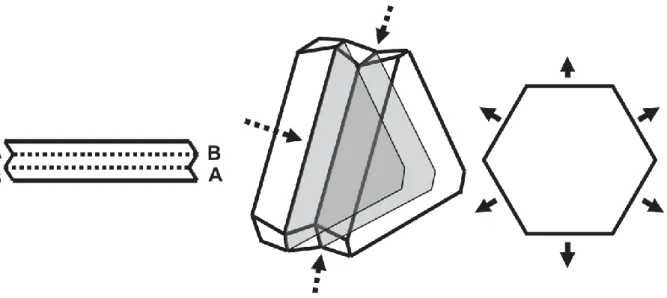
When a single twin plane is formed, the resulting nucleus, at the early stage of growth, is a hexagonal plate due to the six-fold symmetry of fcc structures (Figure 13). Each side of the hexagon is either a concave side or a convex side because of the presence of a twin plane. When atoms diffuse towards the nucleus and adsorb to grow the NC, they can either adsorb on a concave or on a convex face. On the convex side, each atomic site has only three closest neighbors, and the stabilization energy is therefore quite low. On the other hand, on the concave side, newly adsorbed atoms are stabilized by four neighbors from several facets,
increasing the stabilization energy. Atoms will then preferentially adsorb on the concave sides, favoring the growth of the NC along these sides rather than the convex sides. This can be seen on Figure 13 where a singly-twinned nucleus is represented. The growth will be favored on the facets that present a concave-type surface while the convex-type surface does not favor adsorption of new atoms, and will remain unchanged. This can also be explained by the Gibbs-Thomson formula which states that the chemical potential is inversely proportional to the curvature:
∆𝜇 = 𝛾𝛺(1 𝑅⁄ 1+ 1 𝑅⁄ 2)
where ∆𝜇 is the change in the chemical potential, 𝛾 the interfacial free energy, 𝛺 the atomic volume and 𝑅1 and 𝑅2 are the radii curvature.2 For a convex surface where the curvature is positive, the chemical potential change is positive, and the adsorption of atoms is favored on a flat surface rather that a convex surface. On the other hand, for a concave surface where the curvature is negative, the change in the chemical is negative, and the adsorption of atoms on the concave side is favored.
Figure 13: Growth model for a singly-twinned nanoparticle. The A-type concave facets grow more rapidly than B-type convex facets, yielding triangular prisms with exposed B-type facets. From ref.88. Copyright 2005 by John Wiley & Sons, Inc. Reprinted by permission of John Wiley & Sons, Inc.
2.3.2. Multiply-twinned nanoparticles
In the case of multiply-twinned nuclei, several cases can be observed. First, if a second twin plane is parallel to the first one, all the side of the nucleus will exhibit a concave and a convex structure, equalizing the stabilization energy for adatoms, leading to a homogenous growth along the six directions (Figure 14). The out-of-plane growth is however still not favored as atoms prefer to adsorb on concave surfaces rather than flat surfaces. One can further imagine the effect of extra twin planes parallel to the first one: triply-twinned nanoparticles will grow in the six directions, but with different growth rates as some sides
exhibit only one concave-type surface while the others exhibit two. Those nanoparticles will yield non-equilateral hexagons as shown in Figure 15.
Figure 14: Growth model for a doubly-twinned nanoparticle. All six sides now exhibit A-type concave facets (dashed arrows) which causes rapid growth in all the six dimensions (solid arrows). From ref.88. Copyright 2005 by John Wiley & Sons, Inc. Reprinted by permission of John Wiley & Sons, Inc.
Figure 15: Growth model for triply-twinned nanoparticles yielding non-equilateral hexagons. Reprinted with permission from ref.89. Copyright (2011), American Institute of Physics.
Second, because twin planes can also form in directions that are not parallel to each other, different morphologies can be obtained. Indeed, in fcc metals for example, {111} twin planes can form at an angle of 70.53°, while 2𝜋 5⁄ = 72°. This explains why the five-fold symmetry is often present in fcc structures. Thus, icosahedra and decahedra are often formed.90 The remaining gap of 7.35° between two {111} facets is filled by the stretching of the bonds between atoms, which leave their low energy configuration but allow a more energy-favored arrangement of atoms at the surface (Figure 16).91 This stretching, however, is favored for small size of NPs. Calculations show that multiply-twinned Ag seeds are the more energetically favored.92 An increase in the size of the NP increases the stretching of the bonds, decreasing the stability of the structure that was stuck in a local minimum of energy.91 The
stability of the structure therefore depends on their size90,92 but also on a complex interplay between the minimization of the surface energy (shape) and the minimization of the bulk energy (local atomic orientation).93 At small sizes, icosahedra are favored, and as the NP grows, decahedra become predominant at medium sizes, and finally thermodynamically favored Wulff polyhedra at large sizes.2 Simulations performed in 2002 show that for Ag nanoparticles of small sizes (below 170 atoms), the icosahedral shape is dominant, then the icosahedral shape becomes predominant, and above 600 atoms, fcc structures compete with decahedra (Figure 17).94
Figure 16: a. Sketch of penta-twinned decahedral nanoparticle. The tetrahedra that make the decahedron share a common axis, and present an angle of 70.52° between two {111} facets, leaving a theoretical gap of 1.48° between two tetrahedral. From ref.85. Copyright 2010 by John Wiley & Sons, Inc. Reprinted by permission of John Wiley & Sons, Inc. b. TEM image of a gold decahedron nanoparticle. Reprinted with permission from ref.95. Copyright (2008) American Chemical Society.
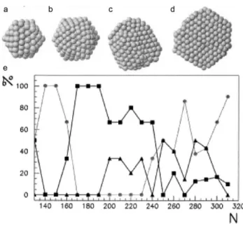
Figure 17: Dependence of shape with size of Ag clusters. a, b, c and d: typical structures obtained for Ag clusters. a. Icosahedron at 147 atoms, b. icosahedron at 309 atoms, c. decahedron at 561 atoms and d. fcc polyhedron at 923 atoms. e. Percentage of different shapes obtained for increasing number of atoms N in the cluster. Circles are icosahedra,
squares are decahedra and triangles are fcc structures. Reprinted from ref.94, Copyright (2002), with permission from Elsevier.
2.4. Inducement of twin defects and oxidative etching
The mere role of ligand templating cannot explain the anisotropic growth of NPs. The nature and shape of the initial seeds definitely play an important role, as seen previously. An interesting aspect is the selection of the initial seeds: why are the anisotropic seeds, less thermodynamically stable, selected to grow over spherical seeds? What induces the twin defects described above, and what is the mechanism that removes the other shapes of NPs to leave in solution up to 90% of anisotropic NCs?96,97
Chen et al.96 have developed a seedless growth of gold nanoplates that yields 90% of monodisperse Au seeds without any purification step. They used hexadecyltrimethylammonium chloride (CTAC) as the surfactant, and iodide ions that have already been observed to direct the anisotropic growth.98 In a mixture of CTAC, potassium iodide and sodium tetrachloroaurate solution, ascorbic acid is added and starts the reduction of Au3+ ions to Au+. NaOH is used to regulate the pH. The obtained nanoplates have a thickness of ≈15 nm and their edge length can be tuned from ≈40 nm to ≈120 nm by changing the concentration of precursors. When the reduction of gold ions is sped up by using HAuCl4, no gold nanoplates can be obtained, showing the importance of the kinetics in obtaining anisotropic NPs (see 2.5). As without iodide no nanoplates can be obtained, it seems to play an important role in the formation of anisotropic structures. Millstone et al. suggested that iodide preferentially binds to {111} facets of Au nanoplates, favoring the anisotropic growth.98 However, iodide can also play the role of selective etchant to remove less stable NCs, leaving in solution only planar structures. Indeed, iodide can oxidize metallic gold nanoparticles following the mechanism:96
4I- + O2 + 2H2O = 2I2 + 4OH
-I2 + I- = I3
-Figure 18: Growth of Au nanoplates through oxidative etching of Au spherical nanoparticles. Reprinted with permission from ref.96. Copyright (2002) American Chemical Society.
Thus, iodide ions can have a dual-function as capping agent that directs growth and as etchant that selects planar structures.
A similar etching mechanism has been observed by Zhang et al. during the synthesis of silver nanoplates.48 When AgNO3 is reduced with NaBH4 in the presence of trisodium citrate and poly(vinylpyrrolidone) (PVP),99 spherical Ag NPs are obtained. However, after the addition of H2O2, the extinction spectra showed a shoulder at 500 nm corresponding to the formation of anisotropic structures. After the optimization of the nature and ratio of reagents, Ag NPs can be obtained with a yield of 100% (with succinate and citramalate replacing the citrate). The proposed mechanism for such a high yield is that upon injection of NaBH4 silver nanoparticles are produced and stabilized by the citrate and borohydride ions. However, due to the presence of H2O2 that acts as a etchant, a dynamic equilibrium in solution is formed between the reduction of metallic ions by NaBH4 and the oxidation of metallic nanoparticles by H2O2 (following the equations: Ag0 + H2O2 = Ag+ + OH- + OH• and Ag0 + OH• = Ag+ + OH-).100 Therefore, the growth of the Ag NPs is hindered by the etchant. Over time, the NaBH4 is consumed and the stabilization of the NPs weakens, allowing for their growth. Due to the presence of the etchant, the resulting NPs exhibit lots of defects, including twin planes that in turn favor planar growth. H2O2 thus removes less stable NPs from solution and introduces twin defects in the remaining ones.
Although the proposed mechanism differs from the previous one, Yu et al. also found that H2O2 plays a crucial role in the formation of metallic nanoplates.101 The equilibrium between the reduction by NaBH4 and the etching by H2O2 is still an important step. However, in basic conditions, where it exists under the form of HO2-, H2O2 acts not as an oxidant, but as a reducing agent: Ag+ + HO2- = Ag0 + HO2•. The formed radical can dissociate into O2 that further oxidizes Ag NPs to form Ag+ ions that can be used for the growth of NPs.
This oxidative etching can be detrimental to anisotropic NPs. Indeed, single crystals are more resistant to oxidative etching that twinned NPs that present at their surface some less stable features. This is somehow contradictory to the previous mechanisms, but it is in fact complementary. The oxidative etching needs to be controlled in such a way as to introduce some twin defects in the NCs but not dissolve them completely. It is possible to selectively eliminate singly- or multiply-twinned NPs from solution by using more or less reactive agents.102–104 Getting rid of the oxidative species might be a solution to control the etching, either by bubbling to remove the oxygen or by using proper ligands that stabilize the surface efficiently.105–107
The mechanism of anisotropic growth is therefore complicated, and strongly depends and the species in solution, in the environment (the oxygen present in air for instance) as well as on the speed of the reaction, the shape of the initial seeds and the ligand templating effect.
2.5. Kinetic control and selective passivation of nanoplate growth
As mentioned previously, the kinetics of the reaction also plays an important role in the shape determination of the NPs. Indeed, a change in the reduction rate of the metallic ions changes the shape of the metallic NPs. By speeding the reduction of Au3+ ions with HAuCl4, nanospheres are obtained rather than nanoplates.96 Similarly, iodide ions have been proposed to bind to {111} facets, stabilizing the nanoparticles, and therefore decreasing the growth rate along the corresponding direction.108 Binding strength of halide ions is the following: Cl-<Br-<I -, decreasing the available metallic surface that acts as a catalyst for the reduction of metal ions.109 Besides, the reduction rate of Au+ ions is strongly affected by the presence of halide ions in the growth solution, and the reduction rate of gold ions will be decreased with the use of a larger halide ion.60,110 The binding of halide ions to the surface of the NPs and their influence on the reduction rate of gold ions are critical in the kinetics of Au NPs growth. For example, the use of a high concentration of iodide ions will yield nanoplates, while the use of bromide yields single crystalline cubes (Figure 19 A-C).60 This is due to the strongly reduced reduction rate of gold ions with iodides: the growth of planar structures requires twin defects to be present in the NPs, defects that appear at low growth rate under kinetic control. Iodide, slowing down the reduction of gold ions, and limiting the availability of the NP surface, allows therefore the formation of twin defects.
This shows the importance of kinetic control in the growth of planar NPs. Slower reduction rate generally leads to more thermodynamically favored shapes with lower-energy facets while, with faster reduction rates, kinetically-controlled growth yields nanoparticles with a variety of shapes, with higher-energy facets. The limit between thermodynamic growth and kinetic growth can be determined by a critical growth speed: under the speed of deposition,
the NPs are driven to grow into their thermodynamically favored shape (plates, given they present twin defects), while speeding the deposition rate forms more complex shapes, energetically unfavorable.53 The reducing agent used (ascorbic acid, NaBH4…), the environmental conditions (pH, temperature…), as well as the use of selective adsorbents on the metallic NPs can dramatically change the growth kinetics. Ascorbic acid is a milder reducing agent than NaBH4, and its reducing strength can be tuned through the change of the pH in the growth solution.59,111 The selective passivation of a given facet also affects the growth. For example, the deposition of Ag atoms on the surface of gold NPs passivates and stabilizes these surfaces, slowing down their growth. This deposition depends on the amount of Ag+ ions in solution, on the reducing agents used, and on the available surface of the Au NPs. Ag will deposit preferentially on the surface with a high coordination number, thus with as many Au atoms as possible.62 (see Figure 19 D-G). The growth of planar nanoparticles is therefore not only controlled by the speed of the reaction, but also by a precise control of the stabilization ligands used for the synthesis (see part 3) and the species present in the growth solution. In the absence of Ag+ ions, halide ions slow down the reduction of metal, slowing down the particle growth, while in the presence of Ag+ ions, halide ions, that also bind to the surface of the NPs, destabilize the Ag layer, speeding up the growth of the NPs.59,60 Furthermore, the growth of planar structures requires the presence of twin planes, which form during the nucleation step: the shape of the original seed is another critical parameter for the determination of the shape of the final NP.112
Figure 19: (A-C) Scanning Electron Microscope (SEM) images of gold nanoparticles synthesized in the presence of (A) 0, (B) 10, and (C) 75 µM of NaI. Adapted with permission from ref.60. Copyright (2012) American Chemical Society. (D-G) SEM images of gold nanoparticles synthesized in the presence of an increasing concentration of Ag+ ions. Higher concentrations
of Ag+ lead to the stabilization of facets with an increasing number of exposed surface atoms.
Reprinted with permission from ref.59. Copyright (2013) American Chemical Society.
Selective passivation of facets during growth also allowed to synthesize even more anisotropic structures, such as Freestanding ultrathin metallic nanosheets (FUMNSs) which
are only a few atomic-layers-thick.113 For example, CO molecules strongly adsorbs on the {111} planes of Pd nanosheets, favoring growth in the perpendicular directions.114
3. Ligand engineering
3.1. Ligand templating
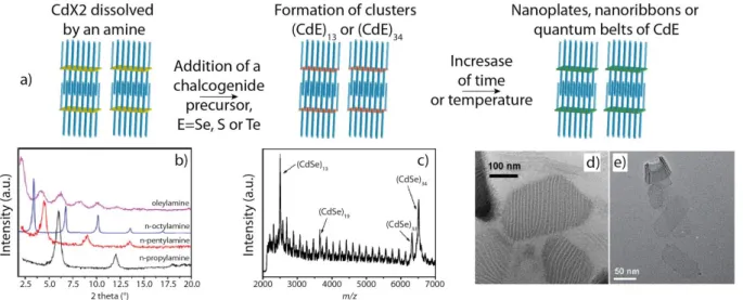
Since the early 2000s, it has been shown that in a synthesis the right choice of ligands could tune the shape of nanocrystals, first leading to spherical, then to rods and to multipods and finally to 2D materials1,115,116. In particular ligands as amines can dissolve metallic salts at room temperature leading to lamellar phases which could serve as template for the growth of nanocrystals. In addition, anisotropic crystal structures are more convenient to give rise to anisotropic shapes nanocrystals. In, 2006 Hyeon and co-workers have shown the synthesis of wurtzite CdSe nanoribbons14 then described as a templated-growth synthesis63. These 2D nanoribbons or nanosheets are equivalent to quantum belts117 and quantum platelets synthesized by Buhro and co-workers.118 The syntheses of these materials are done below 100°C and consist of the reaction of a metallic salt dissolved in a primary amine (for example octylamine) or a mixture of a primary and a binary amine with a chalcogenide precursor such as octylammonium selenocarbamate or selenouera for selenium or trioctylphosphine tellurium (TOPTe) for tellurium. This is a soft template process. Indeed, the dissolution of a cadmium salt, either CdCl2 or Cd(Ac)2 (Ac = acetate), in an amine produces a lamellar amine-bilayer mesophase confirmed by low angle X-Ray diffraction. These 2D nanoparticles exhibit a wurtzite structure with the thickness in the [11-20] direction, the length in the [0001] direction and the width in the [1-100] direction. In addition to CdSe semiconductor, various semiconductors such as CdS, CdTe,119 zinc chalcogenide,120,121 CuS122 or more recently PbS have been synthesized by this path.120
Figure 20: a) Scheme of the three steps synthesis in wurtzite 2D nanocrystals starting with dissolution of a salt in amines, then the introduction of the chalcogenide precursor, finally leading to 2D nanocrystals. b) Low angle X-ray diffraction of the lamellar structure containing
(CdSe)13 clusters in various amines. Adapted with permission from ref.123. Copyright (2013)
American Chemical Society. c) LDI mass spectrum of CdSe magic-sized clusters. Reprinted with permission from ref.124. Copyright (2014) American Chemical Society. d) TEM image of unbundled (CdSe)13 in the stripes. Reprinted with permission from ref.118. Copyright (2011)
American Chemical Society. e) TEM images of CdSe nanosheets. From ref.63. Copyright 2009 by John Wiley & Sons, Inc. Reprinted by permission of John Wiley & Sons, Inc.
Concerning the understanding of the growth mechanism, CdSe remains the most attractive semiconductor and the reader can refer to the following reviews.61,125–127 The cadmium precursor dissolved in amines forms anisotropically ordered layers which will serve as templates for the nucleation and growth of the wurtzite nanoplates once the precursors of selenium is introduced. Both Hyeon128 and Buhro’s groups118 have spectroscopically observed at the early stage of the synthesis the formation of magic sized clusters with a majority of (CdSe)13 and (CdSe)34. The (CdSe)34 magic sized clusters are less thermodynamically stable than the (CdSe)13, thus after few hours or less, only the (CdSe)13 clusters are observed. These clusters are locked into stripes stabilized by the amines, which stack in the thickness and the width directions. If they are unbundled before the crystallization, these stripes will appear as sheets stacked along their width (Figure 20 d). The amines are weakly bound to the clusters, which favors the assembly of clusters up to the formation of nanoplatelets. Thus, these (CdSe)13 are then converted to 2D nanocrystals, either with an annealing step at higher temperature which stay below 100°C or with a longer time of reaction (up to 48h). After crystallization the quantum belts unbundle in their width direction but are stacked in the thickness direction. The addition of a long primary amine, such as oleylamine, and sonication allows the separation of the quantum belts. The as-obtained nanoparticles have a well-defined thickness of few monolayers. The top and bottom surfaces of these platelets are nonpolar with an equal number of cadmium and chalcogenide atoms and are stabilized by uncharged amine. An increase of the reaction temperature thermodynamically favors the synthesis of thicker nanoparticles.
More recently, Buhro and co-workers124 have also shown that instead of using a pure primary amine, a mixture of a primary and secondary amine to dissolve the cadmium precursor allows the formation of CdSe quantum platelets with pure (CdSe)34 magic sized cluster as intermediate of the reaction at room temperature. The (CdSe)34 clusters can also convert to the more thermodynamically stable (CdSe)13 by lowering the temperature to 0°C, but then the annealing temperature should be higher to crystallize them in quantum platelets.
These precisely defined clusters can be achieved with different materials leading either to quantum platelets120 or to quantum nanowires such as ZnTe.129 These quantum wires exhibit similar optical properties as quantum platelets with well defined absorption peaks and unusually thin transitions. Wurtzite quantum platelets and zinc-blende nanoplatelets exhibit the same optical features which will be treated in section 3.2. As original objects, we can cite
the heavily doped Mn:CdSe nanoribbons resulting from the crystallization of doped (CdSe)13 magic-sized cluster which can include up to 2 Mn atoms per cluster, meaning the clusters have for composition (Cd13-nMnnSe13) with n=0, 1 or 2.128 All these nanoplates present a wurtzite structure but more recently it has been shown that PbS nanosheets which present a rock-salt cubic structure could also be synthesized by this soft template process.120
3.2. The case of zinc-blende cadmium chalcogenides nanoplatelets
Cadmium chalcogenides nanoplatelets are one of the most successful syntheses among 2D colloidal systems.130 These 2D nanoparticles127,131,132 have been named nanoribbons, nanobelts,118 nanosheets, nanoplatelets13 (NPLs) by the different groups.133 What makes them appealing is their anisotropic growth controlled at the atomic scale. In these NPLs, the quantum confinement only occurs in one direction, since the lateral extension is typically larger than the Bohr radius (7nm for CdSe). Moreover, there is no roughness along the confined direction. This latter property provides the NPLs with exceptionally narrow optical features. The absence of roughness explains that there is no inhomogeneous broadening. As a result, the spectrum of a single NPL overlaps with the spectrum of the ensemble measurement, while the full width at half maximum can be as low as 7 nm.
CdSe NPLs have been investigated first.13 Their first reported synthesis begins with a mixture made of long-chain cadmium carboxylate (myristate or oleate), selenium powder and octadecene used as non-coordinating solvent. After the degassing step, the temperature is raised. The selenium powder typically dissolves around 150°C and, quickly after that, the solution turns yellow to pale orange. At this point a second metallic precursor is introduced under a solid form and capped with short carboxylic acid (acetate typically). Generally, cadmium acetate is used but the synthesis actually works with other cations. The time of the introduction of this short carboxylic chain is critical. It has to occur when some small nanocrystals are already formed, but before the formation of large QD.
The obtained nanoplates have a parallepipedic shape. The stoichiometry of the precursor also controls the shape of the lateral extension and the shape can be tuned from square (see Figure 21 a) to rectangle. Thanks to the perfect control of their thickness, they tend to stack under pile and can even self-assemble134,135 into µm-scale needles.136 The lateral extension also strongly depends on the thickness of the NPL. Thinner NPLs tend to present a larger lateral extension, up to the point where they are able to roll on themselves132,137 (see Figure 21 b).
In spite of huge progress in the synthesis of the 2D NPLs, they are generally synthetized with spherical 0D QD as by-products. As a result, a selective precipitation is generally conducted. The general procedure takes advantage of the large lateral extension of the NPLs which tends to limit their colloidal stability. Addition of a limited amount of non-solvent
(ethanol or acetone) in the crude mixture after the synthesis generally allows precipitating the NPLs while keeping the QD in solution.
To reduce the amount of solvent used during this cleaning procedure, electrophoretic sorting of the NPLs is also possible.138 By applying a “large” electric field (400V over 1cm) on the solution resulting from the synthesis in presence of acetone, the NPLs get deposited on the positive electrode with a selectivity (defined as the ratio of the deposition rates) of 400 compared to QD.
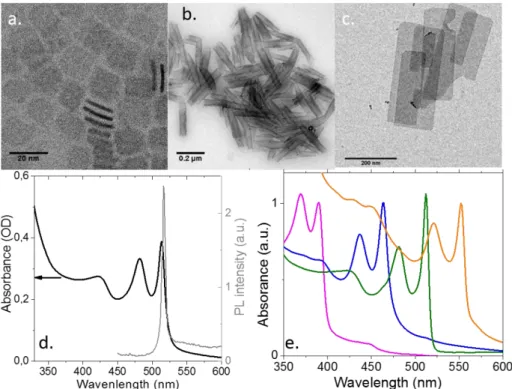
Figure 21: TEM Images of CdSe NPLs with small (a) and large lateral extension (b). The latter rolled on themselves. c. TEM image of CdTe NPLs. d Absorption and photoluminescence spectra of CdSe NPLs with a first excitonic feature at 510nm. There is almost no Stoke shift between the maximum of the absorption and the photoluminescence (PL) signal. The PL linewidth is 10nm. e. Absorption spectrum of CdSe NPLs with different thicknesses and presenting a first optical absorption feature at 390nm, 460nm, 510nm and 550nm.
The most striking property of the NPLs is their exceptionally narrow optical feature (Figure 21 d), with full width at half-maximum (FWHM) as low as 7nm for a photoluminescence (PL) signal around 500nm. Thanks to their perfectly controlled thickness, no inhomogeneous broadening is observed and the PL signal of a single NPL overlaps with the signal obtained from an ensemble.139 The homogeneous broadening is typically below 2kbT. For core only structures, we obtain PL efficiency of 20%.13 A general trend is that nanoplates with a smaller lateral extension tends to have a larger PL efficiency. We believe that such behavior result from the larger probability for the large object to include defect acting as a non-emissive
recombination center. The NPLs present almost no Stoke-shift between the energy of the absorption and the energy of the emission (see Figure 21 d). As the thickness rises, the optical features get redshifted as expected from quantum confinement.13 However, due to the perfect control of the thickness with an integer number of layer, the optical features can no longer be controlled continuously as for spherical objects, see Figure 21 e. In the case of CdSe NPLs, different populations can be obtained with a first excitonic feature at 390, 460, 510 and 550 nm. Possibly, if the lateral extension is very small, some lateral confinement occurs and the peaks can be slightly blue-shifted. In these CdSe 2D quantum wells, the optical features have been attributed to the heavy hole-electron and light hole-electron transition.140 The dynamics of the exciton is also strongly impacted by the 2D aspect of the nanoparticles. Indeed, the typical PL decay time of CdSe NPLs is of a few ns at room temperature, which is one order of magnitude faster than for QD at the same wavelength and with similar quantum yield. At low temperature, the exciton lifetime get even shorter and can be as low as 150 ps.139
From an experimental perspective, the absorption cross section and the extinction coefficient141 have been recently determined and are of utmost interest for the determination of the NPLs concentration. Surprisingly the scale of the absorption seems to have a dependence with the surface which is superlinear.
Quickly after the synthesis of the CdSe NPLs, the procedure has been extended to other chalcogenides.140,142 CdS nanoplates come with a large lateral extension. Compared to CdSe, their optical absorption is broader. The broadening results from the low spin-orbit coupling in CdS which tends to limit the splitting of heavy-hole and light-hole bands. As a result, the two transitions, which appear splitted in CdSe, are here only splitted by an energy smaller than their homogeneous broadening. Finally, the PL efficiency of pure CdS NPLs is low. CdTe nanoplates are the one with the narrowest excitonic features, down to 7 nm, while a value of 12 nm is more typical for CdSe NPLs. CdTe NPL are obtained using TOPTe as precursor and cadmium propionate instead of the acetate. Moreover, the CdTe NPLs are synthetized with the largest lateral extension up to 1µm (see Figure 21 c).
3.3. Thickness tunability
In this section, we will discuss the thickness tunability of zinc blende cadmium chalcogenides nanoplatelets. In this cubic structure, all the three directions x, y and z should be equivalent. Nevertheless, during the synthesis, the introduction of an acetate salt “breaks” the isotropic growth of nanocrystals and leads to nanoplatelets of 2, 3, 4 or 5 monolayers. The thickness of the nanoplatelets is in the [001] direction and a monolayer is defined as a succession of a plan of cadmium and a plan of chalcogenide in the z direction. The top and bottom surfaces are terminated by cadmium planes and are passivated by the oleate ligands
(see Figure 6). When the nanoplatelets stack, the space between two nanoplatelets is of few nm132,134 which corresponds to two interpenetrated oleate ligands.
Although the optical properties of the CdSe zinc-blende nanoplatelets and the wurtzite quantum platelets are similar, the growth conditions are different. While for the wurtzite nanoparticles magic-sized clusters are intermediate of the reaction (discussed in section 3.1), such clusters have not been highlighted as intermediate for the zinc-blende nanoplatelets.130 If the growth of zinc-blende nanoplatelets occurs via the formation of some magic-sized clusters, they react much faster than they are produced and it remains difficult to isolate them.
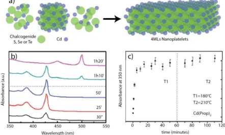
Thus, the growth of zinc-blende nanoplatelets can be seen as a two-step process: (1) nucleation of nanocrystals and (2) growth of nanocrystals up to some sizes which are seeds for nanoplatelets, followed by the lateral extension of these seeds leading to nanoplatelets initiated by an acetate or a propionate salt130 (Cd(prop)2) (see Figure 22 a). During the growth of the nanoplatelets, the exciton absorption spectra continuously red shifts as the nanoplatelets grow, expressing the weakening of the quantum confinement from 0D nanocrystals to 2D nanomaterials. It should be pointed out, that in 2014 Asaula and co-workers143 have synthesized CdSe nanoplatelets with pure cadmium octanoate in the presence of selenourea without using a mixture of a short and a long carboxylate chain. Nevertheless, the crystal structure of the synthesized nanoplates remains unclear. In the following discussion we will mostly focus on the syntheses with mixture of two carboxylate chains.
Figure 22: a) Scheme of the two-step growth of cadmium chalcogenide nanoplatelets, b) absorption spectra of CdTe nanoplatelets at different times during a reaction first at 180°C and then at 210°C (dashed line) with Cd(prop)2 as a short chain carboxylate. c) Absorbance at
350nm as a function of time for the CdTe nanoplatelets growth. Adapted with permission from ref.142. Copyright (2013) American Chemical Society.
Nanoplatelets of 2 and 3 monolayers (MLs) are the easiest to synthesize. Indeed, a mixture of Cd(RCOO-)2 (R=CH3 or C2H5) and Cd(R’COO-)2 (R’=CnH2n+1 with n>14) in presence of a chalcogenide precursor in mild heating conditions (lower than 220°C) are sufficient to synthetize the two thinnest populations of nanoplatelets without production of quantum dots as byproducts. It is also possible to anneal 2MLs nanoplatelets to get 3MLs nanoplatelets. As an example, Figure 22 b and c present the absorption spectra of constant volume aliquots of CdTe nanoplatelets during a reaction and their optical density at 350 nm as a function of time.142 During the first step of the synthesis, 2MLs nanoplatelets are formed absorbing at 428 nm for their first excitonic peak. After 15 minutes the absorption at 350 nm - which reflects the total amount of crystalline CdTe - is stable, so all the precursors were consumed. Finally, after 60 minutes at 180°C, the temperature is increased up to 220°C, and a change in the absorption spectra occurs. The thinnest nanoplatelets of 2MLs disappear in favor of the 3MLs nanoplatelets but with a constant optical density at 350 nm. It seems that the transformation comes from either an intra-reorganization of the nanoplatelets or from a dissolution of the 2MLs NPLs and a fast recrystallization of 3MLs NPLs. There is no addition of free precursors in solution on top of the already existing nanoplatelets since the total amount of crystalline CdTe remains constant (if there was deposition of an additional layer in the thickness, it should lead to an increase of 40% of the absorption at 350 nm). Moreover, we could have expected an increase of two monolayers instead of one (leading to nanoplatelets with their first excitonic peak at 555 nm), since the NPLs present two equal opposite surfaces which should react the same way. In general, higher temperature leads to thicker nanoplatelets. This transformation from 2MLs to 3MLs nanoplatelets may be explained by the really thin thickness of the initial nanoplatelets of only one lattice parameter. The relaxation of the top and bottom surfaces induced by the ligands may weaken the crystalline structure of the nanoplatelets which present 40% of their atoms on their surface. Besides, the annealing may cause a rearrangement of the atoms leading to more stable 3MLs crystalline nanoplatelets with only 28% (2/7) of their atoms on their surface. Another interesting feature is the total transformation from 2MLs-thick nanoplatelets to 3MLs-thick nanoplatelets. Indeed, once a 2D nucleus appears on surface of a NPL, the subsequent monolayer growth happens rapidly144 in order to minimize the surface energy.125
![Figure 11: Model of a twin plane in a face-centered cubic (fcc) metal: (A) fcc lattice; (B) fcc lattice with the repeating « abcabcabc » stacking pattern annotated; (C) annotated fcc lattice from (B) oriented to the [110] zone axis so that the](https://thumb-eu.123doks.com/thumbv2/123doknet/14517788.530847/19.892.133.782.105.279/figure-centered-repeating-abcabcabc-stacking-annotated-annotated-oriented.webp)