HAL Id: cea-02389201
https://hal-cea.archives-ouvertes.fr/cea-02389201
Submitted on 2 Dec 2019HAL is a multi-disciplinary open access archive for the deposit and dissemination of sci-entific research documents, whether they are pub-lished or not. The documents may come from teaching and research institutions in France or abroad, or from public or private research centers.
L’archive ouverte pluridisciplinaire HAL, est destinée au dépôt et à la diffusion de documents scientifiques de niveau recherche, publiés ou non, émanant des établissements d’enseignement et de recherche français ou étrangers, des laboratoires publics ou privés.
Transient behavior of ASTRID with a gas power
conversion system
F. Bertrand, G. Mauger, M. Bensalah, P. Gauthe
To cite this version:
F. Bertrand, G. Mauger, M. Bensalah, P. Gauthe. Transient behavior of ASTRID with a gas power conversion system. Nuclear Engineering and Design, Elsevier, 2016, 308, pp.20-29. �10.1016/j.nucengdes.2016.08.005�. �cea-02389201�
Transient behavior of ASTRID with a gas power conversion system
F. Bertrand
1, G. Mauger, M. Bensalah, P. Gauthé
CEA, DEN, DER, F-13108, Saint Paul-lez-Durance, France
Keywords
SFR, ASTRID, transient analysis, gas PCS, loss of off-site power, depressurization, system regulation
Abstract
The present article is dedicated to preliminary transient studies carried out for the analysis of the system
overall behavior of the ASTRID (Advanced Sodium Technological Reactor for Industrial Demonstration)
demonstrator developed in France by CEA and its industrial partners. ASTRID is foreseen to demonstrate
the progress made in SFR technology at an industrial scale by qualifying innovative options, some of
which still remain open in the areas requiring improvements, especially safety and operability. Among the
innovative options, a gas power conversion systems (PCS) is envisaged. In this latter innovative PCS, the
working gas is nitrogen whose flow rate delivers power to a turbine driving with the same shaft two
compressors (low and high pressure) separated by an intercooler. The other part of the work delivered by
the gas is used to drive the alternator that produces electricity. The main objective of such a PCS consists
in avoiding physically the possibility of a sodium/water reaction with the secondary circuit but the impact
of this PCS on the control of the accidents has also been studied. The main purpose of the studies
presented in the paper is to assess the dynamic behavior of ASTRID including a gas PCS with the
CATHARE2 code. The first transient presented deals with a loss of off-site power and has been
calculated for the gas PCS but also for a classical steam/water PCS for comparison purpose. Then typical
transients of gas system have been investigated. Several families of initiating events affecting the PCS are
studied: breaches in the ternary circuit, a loss of power supply, a loss of main heat sink and the spurious
1
opening of the turbine by-pass valve. Regarding this last transient, sensitivity studies have shown that an
adequate design of the turbomachine by-pass lines allows a control of the event without shutdown.
Moreover, regulating actions following the scram are also investigated in order to take benefit of the PCS
in order to remove the decay heat.
1. Introduction
After a brief presentation of the ASTRID reactor main design options, the stress is put on the
presentation of the power conversion system (PCS). In this gas innovative PCS designed by ALSTOM,
the working gas is nitrogen whose flow rate delivers power to a turbine driving with the same shaft two
compressors (low and high pressure) separated by an intercooler. The other part of the work delivered by
the gas is used to drive the alternator that produces electricity. Moreover, a recuperator enables to
pre-heat the gas flow entering the gas/sodium pre-heat exchanger with the gas exhausting from the turbine. The
main objective of such a PCS consists in physically avoiding the possibility of a sodium/water reaction at
the interface between the secondary and the ternary circuit. In the following part of the paper, the main
features of the CATHARE2 modelling of nitrogen cycle currently envisaged for ASTRID are detailed as
well as the system actions simulated in the CATHARE2 input deck for transient calculations. Finally, the
calculation results are presented and the consequences on the reactor (thermal shock, long term
behaviour and heat removal process) of the various transients simulated are assessed. First, the
seam/water and gas PCS’s are compared in case of LOOP. Then the behaviour of ASTRID with a gas
PCS is presented for typical transients of gas circuits.
2. Overview of ASTRID design
ASTRID, standing for Advanced Sodium Technological Reactor for Industrial Demonstration consists in
a 1500 MWth SFR pool type reactor of about 600 MWe that is an integrated technological demonstrator
designed for industrial-scale demonstration of 4th generation sodium-cooled fast reactor (SFR) safety and
in dedicated areas (in particular safety, operability and in service inspection and repair). ASTRID will
also be designed to perform waste transmutation in order to demonstrate the industrial feasibility of this
technique for reducing volume of end waste and lifetime of ultimate waste. Additionally, ASTRID is
being designed to fulfil the GENIV criteria in terms of safety, sustainability, economy and proliferation
(Chenaud at al., 2013). Various innovative options have been investigated during the first stage of the
conceptual design carried out in 2011 and 2012 in order to improve safety on the following points:
- prevention of core degradation and mitigation of its effects (innovative CFV2 core design
with a low total voiding effect has been retained);
- elimination of the possibility of sodium/water reaction at the interface between secondary
loops and ternary circuit (gas PCS whose transient behaviour is presented in this paper);
- enhancement of the reliability of the DHR systems.
2.1. Core design
The so-called CFV concept (version 1) featured by a low global Na voiding effect has been designed by
CEA in order to increase the margin up to sodium boiling in case of unprotected transient (Chenaud et al.,
2013) and also to reduce the severity of a primary power excursion should it occur in case of a severe
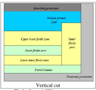
accident (Lemasson et al., 2013; Bertrand at al., 2016). This core is an axial heterogeneous core (Fig. 1).
The low voiding effect of this core results mainly from the presence of a sodium plenum above the upper
fissile zone (Sciora et al., 2011) combined to the presence of a fertile plate in the inner zone of the core
(Fig. 1). The height of the outer fissile zone enables the void reactivity effect to be lowered as well. All
these effects lead to a reactivity decrease when the upper part of the core experiences a sodium thermal
expansion or sodium boiling. Finally the overall voiding effect for this version of the core is equal to
-0,5 $ (one Dollar being the delayed neutron fraction).
2
Vertical cut
Fig 1. General CFV core geometry
2.2. Primary and secondary systems overview
The ASTRID pool type primary circuit includes 3 primary pumps and 4 intermediate heat exchangers
(IHX) immersed in the reactor vessel (Fig. 2).Each of the 4 secondary loops delivers a fourth of the core
power (375 MWth) to 3 modular steam generators (SG) or to 3 modular sodium/gas heat exchangers
(SGHX); the modularity enables the impact of an event in a SG or SGHX to be reduced (Le Coz, 2013).
Finally for both options, an argon covered expansion vessel is foreseen in order to protect the loop against
an accidental pressure wave.
The main features of the reactor operating point are provided in Table
1 for the primary and secondary circuits. The operating point is the same for both PCS options
except for the ternary side.
Tab 1. Nominal operating point of the secondary and primary circuits
Primary Circuit
Core flow rate (kg/s) 7900
Fraction of the flow for vessel cooling (kg/s) 600
Primary flow rate (kg/s) 8500
Core inlet/outlet temperature (°C) 400/550
Core inlet/outlet pressure (bar) 4.5/1.9
Secondary Circuit
Secondary flow rate (kg/s) 6370
IHX inlet/outlet temperature (°C) 345/530
Pump inlet/outlet pressure (bar) 1.9/7.1
2.3. Power conversion system (PCS) 2.3.1. Steam/water PCS
The steam/water PCS option classically includes steam modular SGs (three by secondary loop), a steam
turbine delivering the reactor power to an alternator, a condenser and finally a feed-water pump.
Considering the operating point and the ternary flow rate (about 680 kg/s), the efficiency of the reactor
with the steam PCS would be about 41 % according to first assessments.
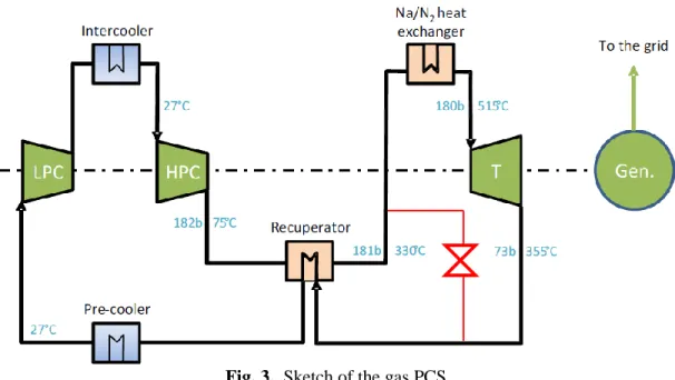
2.3.2. Gas PCS
The gas PCS using nitrogen as a working gas is presented on Figure 3 with its associated operating point
(laffont et al., 2013; Cachon et al., 2012). The choice of the PCS gas has been performed by taking into
account heat transfer, compression work, pressure level and its simplicity of operation. Consideration of
all these criteria led to the nitrogen at 180 bars (turbine inlet) as the reference coolant. A Brayton cycle,
which has never been implemented in any sodium reactor but has been investigated for High Temperature
Reactors (HTR) has been chosen. This kind of cycle provides the best efficiency. The PCS flow rate is
about 7160 kg/s and a by-pass line (preliminarily located in red in Fig. 3) enables to stop or to regulate the
TM speed by reducing the outlet/inlet pressure ratio, the by-pass opening consisting in an aerodynamic
brake. Basically, the PCS includes a turbine driving two compressors mounted on the same shaft3. Since
3
the realization of the calculations presented in the present paper, the design of the PCS has evolved and is
made now of two shaft-lines, each one including two symmetric turbines arranged in parallel, a low
pressure compressor and a high pressure compressor plus an alternator. The efficiency of the whole gas
compression is improved by means of a pre-cooler and an intercooler separating the 2 compression
stages; these heat exchangers (HX) are cooled by the heat sink of the reactor. Finally, a so-called
recuperator HX permits to pre-heat the gas flow before entering the SGHX and to cool it before entering
the pre-cooler. The net efficiency of the reactor considering this PCS option would be about 37.5 %
according to preliminary assessments (laffont et al., 2013). A multiple pipe design in parallel has been
adopted in order to limit the gas velocity in the pipes (minimization of pressure drop) and in the same
time to limit the maximum pipe diameter at about 1 m for mechanical and manufacturing reasons. A
sensitivity study on the cycle parameters has shown that the turbomachine performance and the pressure
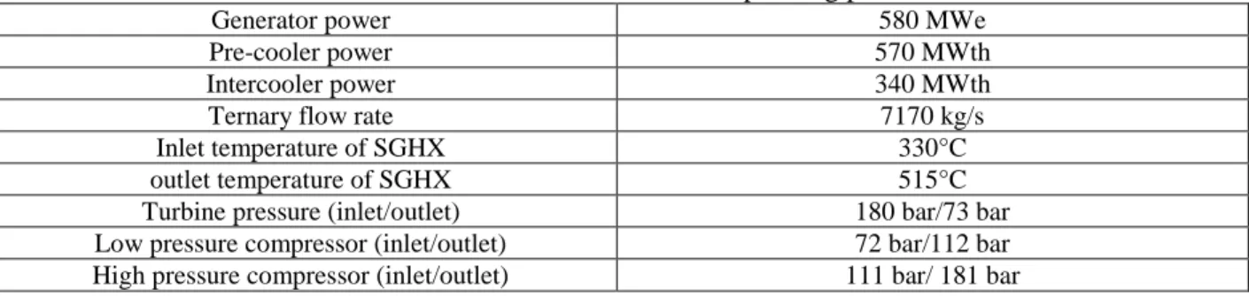
losses are the most influent parameters in terms of efficiency. The main operating parameters of the PCS
are presented in Table 2.
Tab. 2. Main features of the PCS operating point
Generator power 580 MWe
Pre-cooler power 570 MWth
Intercooler power 340 MWth
Ternary flow rate 7170 kg/s
Inlet temperature of SGHX 330°C
outlet temperature of SGHX 515°C
Turbine pressure (inlet/outlet) 180 bar/73 bar
Low pressure compressor (inlet/outlet) 72 bar/112 bar
High pressure compressor (inlet/outlet) 111 bar/ 181 bar
Fig. 3. Sketch of the gas PCS
(LPC: low pressure compressor; HPC: high pressure compressor; T: turbine; Gen: generator)
3. Brief presentation of the CATHARE2 modelling of the system
3.1. Primary and secondary circuits
The whole system has been modelled partly by CEA and partly by AREVA and the calculations have
been run with CATHARE2 v25_3 mod2.1 (Geffraye et al., 2009). The CATHARE2 code is a 6-equations
thermalhydraulic system code. Properties of sodium have been implemented in the code but the form of
the friction and heat transfer correlations are the same as in the water standard version. The following
neutronic effects are modelled: Doppler, sodium density, cladding expansion, fuel expansion, hexcan
(HC) expansion, diagrid expansion and finally the reactivity feedback resulting from relative location of
control rods within the core. All these reactivity coefficients are included in the point kinetics of neutron
physics of CATHARE2 including 8 groups of delayed neutrons and 4 groups of fission products. The
core channels, the IHX, the fraction of the primary flow cooling the vessel and the inlet/outlet region of
the pumps are modelled thanks to 1-D CATHARE2 axial elements. The flow distribution within the cold
and hot collectors is modelled thanks to a dedicated volume decomposition in several volumes whose
is modelled with a single loop representing the 4 loops, connected to the primary system by means of a
single IHX representing the 4 IHXs. A secondary pump is modelled and enables the loss and variation of
flow to be simulated.
3.2. Nitrogen PCS
The PCS system is fully modelled in the CATHARE2 input deck as represented on Figure 4. This
modelling includes a comprehensive TM module whose performance maps are derived from CEA gas fast
reactor (GFR2400) performance maps (Widlund at al., 2005) but adapted to a nitrogen circuit. The
parameters of the heat transfer correlation (Dittus-Boelter form) for plate type Na/gas exchangers used in
CATHARE2 have been derived from CFD calculations. The next step of modelling will be to include the
performance maps elaborated by ALSTOM in order to have a more realistic design and its associated
modelling. The SGHX modules are associated to a weight equal to 12 and the recuperator to a weight of
18 in order to cope with the pre-design of the PCS. The pre-cooler and intercooled are respectively
divided in 72 and 60 modules represented by a single HX in CATHARE2 associated to their weight. The
whole nitrogen inventory of the circuit is around 560 tons. The rotating mass equation is solved on the
Fig. 4. Sketch of the CATHARE2 modelling of the PCS
(SGHX: sodium/gas heat exchanger, NSS: Nitrogen Supply System)
4. System actions and regulations adopted for transient calculations
This section is devoted to the transient analysis of ASTRID equipped with a gas PCS. In a first general
part, the system actions are presented (actions triggered via the input deck after the transient initiation)
and further on, the analysis of the reactor behaviour when facing specific transients of the gas PCS are
presented. Additionally, the capability to remove decay heat from the system with the gas PCS is also
preliminarily investigated. Finally a sensitivity study to the design of the TM by-pass line is also
provided, the aim of this design alternative being to improve the capability of the reactor to withstand the
transient without scram.
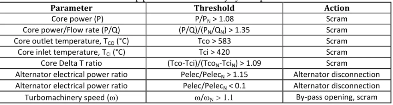
4.1. Reactor trip system modelling and other system actions
The transient input deck includes several trip parameters enabling the reactor scram to be actuated and the
PCS to be protected (Table 3). Moreover, in case of reactor trip, the rotation speed of the primary pumps Precooler LP Compressor HP Compressor Components Breaches By-pass Recuperator SGHX AM_SGHX
is decreased to 25% of its nominal value in 30s and the rotation speed of the secondary pumps is reduced
to 15% of its nominal value in 9s.
Table 3. Reactor trip parameters and ternary system protection actions
Parameter Threshold Action
Core power (P) P/PN > 1.08 Scram
Core power/Flow rate (P/Q) (P/Q)/(PN/QN) > 1.35 Scram
Core outlet temperature, TCO (°C) Tco > 583 Scram
Core inlet temperature, TCI (°C) Tci > 420 Scram
Core Delta T ratio (Tco-Tci)/(TcoN-TciN) > 1.09 Scram
Alternator electrical power ratio Pelec/PelecN > 1.15 Alternator disconnection
Alternator electrical power ratio Pelec/PelecN < 0.1 Alternator disconnection
Turbomachinery speed ( /N > 1.1 By-pass opening, scram
4.2. System regulation
Several regulation actions are implemented in the input deck in order to be able to remove the decay heat
and to maintain all the circuit in acceptable conditions. In the frame of those exploratory studies, some
regulations have been settled in order to control the power extracted by the ternary circuit (Table 4).
Table 4: regulation system in order to control the power extracted by the ternary circuit (the regulations implemented depend on the calculated transient)
Variable to regulate Targeted value Action Cooler flow rate 20 % of QN Boundary condition
Turbomachine speed 3000 rpm By-pass valve
opening Turbomachine
pressure inlet 12 bars
Surge valve of NSS opening
5. Pressurized PCS transients
The transient investigated in this paper have been distinguished between transients with PCS under
pressure and PCS depressurized, those latter occurring in case of breaches. Among the pressurized
transients, the black-out transient, the loss of off-site power (LOOP) and the spurious opening of by-pass
valves of the TM have been simulated, including a comparison between steam/water and gas PCS. The
dedicated DHR loops plugged on the primary circuit of the reactor are not used during the transient but
the TM speed is kept as long as possible at 3000 rpm by means of a regulated opening of its by-pass valve
5.1. LOOP (Loss Of Off-site Power)
5.1.1. Comparison of the reactor behaviour depending on the nature of the PCS
As far as the gas PCS is concerned, the initiating event (IE) causing this transient is featured by the
alternator disconnection and the instantaneous shutdown of the cooling flow rate on the cold side of the
pre-cooler and of the intercooler. Regarding the steam/water PCS, the transient consists in a decrease up
to a residual value of the flow rate of feed water of the SG in 30 seconds. The actions triggered by the
LOOP on the primary and secondary side are the pump trip according to the speed decrease
aforementioned and an emergency supply (by a Diesel engine) of the primary and secondary pumps
enabling their rotation at their back-up speed value. The transient effects are investigated first in case of
failure of the reactor shutdown (unprotected transient) and then by considering the reactor scram.
5.1.1.1. Unprotected transient
In order to assess and to compare the natural behaviour of the core in case of LOOP depending on the
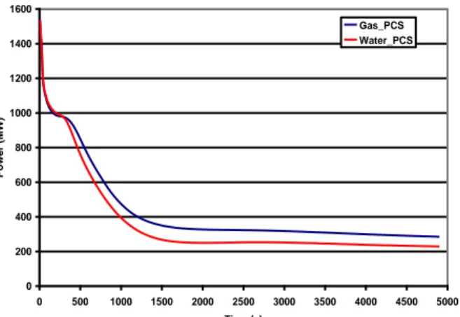
PCS, calculations have been performed without scram in the case of the CFV core (Fig. 5). The core
power (Fig. 5), governed by the reactivity feed-back is lower for the water PCS than for the gas PCS. This
is due to a core inlet temperature that is higher in the case of the water PCS thus favoring the diagrid
expansion. This temperature difference is explained by the difference of power removed by the ternary
side depending on the PCS. In the case of the water PCS, the SG is dried out in approximately 30 s after
the beginning of the transient, that is, with the same dynamics as the feed water decrease. After its
dry-out, the SG still removes some power during 900 s but only several Megawatts whereas the gas PCS
removes about 100 MW thanks to a substantial residual flow rate of about 250 kg/s driven by natural
Fig. 5. Comparison of core power evolution in case of unprotected LOOP for gas
and steam/water PCS
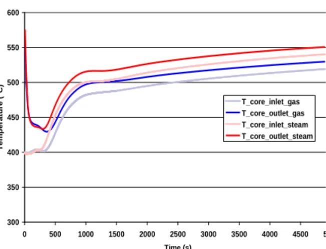
5.1.1.2. Protected transient
The actuation of the scram (Tab. 3) is triggered according to the reach of the threshold of the power to
flow rate ratio for the water PCS (at 3.7 s) whereas regarding the gas PCS, the threshold of the TM
over-speed is reached (1.3 s) and induces the reactor scram and the opening of the TM by-pass line. The core
power is the same for the 2 PCS since the transient occurs in a residual power regime. So it is not
influenced by the thermalhydraulic parameters. For the gas PCS, as soon as the by-pass line is fully open
(at 4 s), the TM speed decreases up to zero in about 400 s. Despite this absence of rotation of the
turbomachinery, the ternary side remains featured by a gas flow rate ranging from about 200 kg/s at the
beginning of the transient down to 100 kg/s at 5000 s thanks to exchanges through the recuperator that
generates natural circulation. This behavior, already observed in the unprotected case, leads to more
moderate heating of the secondary inventory and thus to a moderate primary inventory heating as well
(Fig. 6). Even if the difference is about 20 or 30 °C, the impact on the vessel creep could be important for
the long term transient.
0 200 400 600 800 1000 1200 1400 1600 0 500 1000 1500 2000 2500 3000 3500 4000 4500 5000 Time (s) Po wer (MW) Gas_PCS Water_PCS
Fig. 6. Comparison of core temperature evolution in case of protected LOOP for gas PCS and for
steam/water PCS
5.1.2. Decay heat removal with the gas PCS
During the LOOP transient, emergency electrical supply is available to deliver a back-up flow rate to the
primary and secondary pumps as well as to the water-feeding system of the coolers. The aim of this
sub-section is to present the sensitivity of the system behavior to a back-up flow rate in the coolers4.
Conversely to calculations presented in section 5.1.1, in this set of calculation, regulations actions
presented in Table 4 are simulated in order to keep the ternary side under operation as long as possible as
a temporary heat sink. Figure 7 shows that as soon as a back-up flow rate is available (even only 5 % of
the nominal flow rate), the core inlet temperature decreases of at least 150°C in one hour. It is interesting
to observe that the minimum flow rate tested (5%) is enough to keep the TM under operation. Therefore,
the ternary flow rate and the cold source is enough to cool the core adequately, thus providing a
substantial additional delay before switching the decay heat removal to the dedicated in-vessel loops.
Moreover, the rotation of the TM enables to reduce the hot shock on the primary vessel by compensating
the heating due to the loss of flow on the primary and secondary circuits (+ 20°C at the IHX outlet instead
4 This study is only performed in order to assess the behavior of the system no matter what the decisions will be
taken regarding the systems rescued: in particular, at that time, it is not foreseen to have an emergency electrical supply for the coolers.
300 350 400 450 500 550 600 0 500 1000 1500 2000 2500 3000 3500 4000 4500 5000 Time (s) Tempera ture ( °C ) T_core_inlet_gas T_core_outlet_gas T_core_inlet_steam T_core_outlet_steam
of + 75°C when the TM is stopped). Finally, the TM stops after approximately 1 h whatever the flow rate
of the coolers.
Fig 7. Core inlet temperature and turbomachine rotation speed for various back-up flow rates of the coolers (from 0 to 25 %)
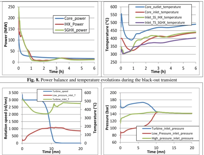
5.2. Black-out
This transient results from the total loss of electrical supply: there is no back-up flow rate delivered by
means of emergency electrical supply and the water feeding of the coolers is unavailable as well. The
reactor trip is actuated at the beginning of the transient. The pump run-down is governed by their inertia.
The power balance between the core and the reactor circuits and the temperature evolution across the core
and on the interface between the secondary and ternary circuits are presented on Figure 8. A cold shock
affects all the circuits because of the heat extraction by the ternary circuit thanks to a substantial flow rate
that remains in this circuit thanks to the TM operation and to the gas expansion in it (Fig. 6). This can be
observed on Fig. 5 because the nitrogen temperature at the inlet of the SGHX decreases up to 300°C
because only the decay heat is transferred to the PCS and yet, its flow rate remains very high as long as
the TM is under rotation. 0 100 200 300 400 500 0 20 40 60 Tem p e ratu re ( °C) Time (mn) 0% 5% 15% 25% 0 500 1 000 1 500 2 000 2 500 3 000 3 500 0 10 20 30 40 50 60 70 S p e e d ( rd / m n ) Time (mn) 0% 5% 15% 25%
Fig. 8. Power balance and temperature evolutions during the black-out transient
Fig. 9. Rotation speed, temperature and pressure evolution across the turbomachine
After 10 minutes, the balance between the heat transferred to the PCS from the core and the heat released
by the coolers leads to the TM rundown (Fig. 9). As a consequence, at this time, the PCS pressure is
balanced around 140 (Fig. 9) bars and the secondary and ternary side temperatures begin to increase. At
1 h, a thermal and power balance is reached and the heat removed by the ternary side becomes lower than
the decay heat and the primary sodium temperature begins to increase. Actually, even after the primary
and secondary pumps shutdown and the TM rundown, natural circulation flows in each circuit drive the
whole reactor cooling. However, this result should be to confirm considering the uncertainty on the
natural circulation regime calculation (pressure head of the stopped pumps, performance maps of the TM
and circuit elevation are not assessed adequately). Nevertheless, this result indicates that the heating rate
of the whole system is very low and that thanks to the Brayton cycle and of the inertia of the reactor 0 50 100 150 200 250 0 1 2 3 4 5 6 Pow e r ( M W) Time (h) Core_power IHX_Power SGHX_power 250 300 350 400 450 500 550 600 0 1 2 3 4 5 6 Tem p e ratu re ( °C) Time (h) Core_outlet_temperature Core_inlet_temperature Inlet_SS_IHX_temperature Inlet_TS_SGHX_temperature 0 100 200 300 400 500 600 0 500 1 000 1 500 2 000 2 500 3 000 3 500 0 10 20 Tem p e ratu re ( °C) R o tat io n sp e e d ( rd /m n ) Time (mn) Turbine_speed Low_pressure_inlet_T Turbine_inlet_T 60 80 100 120 140 160 180 200 0 5 10 15 20 P ressur e (b ar ) Time (mn) Turbine_inlet_pressure Low_Pressure_inlet_pressure High_pressure_inlet_pressure
cooling circuits, the PCS enables the decay heat to be removed more than 6 hours without reaching the
temperature level of the nominal state of the reactor.
5.3. Spurious opening of by-pass valves
Various flow paths are possible (Fig. 10) in order to by-pass the turbine and practically, a mix of gas
taken in the cold leg (opening of by-pass2) and of gas taken in the hot leg (opening of by-pass1) is
injected in the exhaust pipe of the turbine (opening of by-pass4). The transients calculated in this paper
deal respectively with the spurious opening of the lines by-pass1 + by-pass4 (called BYP1) and of the
spurious opening of the lines by-pass2 + by-pass4 (called BYP2). The spurious opening of the valves is
realized in 3 s. The line by-pass 4 is open before the transient and the lines by-pass1 and by-pass2 are
respectively made of 2 pipes of 60 cm diameter and when the transient occurs, 1 over 2 lines are open. As
observed on figure 11, the case “BYP2” leads to a fast rundown of the TM due to the cold temperature of
the gas in the cold leg, the flow rate by-passing the turbine being higher than in the case “BYP1”. As a result, the flow rate in the PCS is reduced faster in the case “BYP2” than in the case “BYP1” and the
heating of the sodium at the core inlet occurs earlier (Fig. 11).
Fig. 10. Sketch of the by-pass line system in the PCS (HP comp and LP comp : high pressure and low pressure compressors; HP recup and LP recup: high pressure and low pressure recuperator sides; SGHX:
sodium gas heat exchanger)
HP Comp LP Comp
HP Recup LP Recup
Fig. 11. TM rotation speed and temperature across the core for by-pass valve opening transients The reference design option including 2 by-pass pipes for the parts of the circuit called BYPASS1 and
BYPASS2 leads to an over-speed of the TM equal to 114 % of its nominal speed. By keeping the same
over-speed, the BYPASS1 and BYPASS2 lines have been sub-divided into smaller pipes (6 pipes of 25
cm diameter) in order to limit the transient impact of the opening of one single line. In the case “BYP2”
the reactor trip threshold are not reached and thus, the reactor is not scrammed, even after a long time.
The electrical power delivered to the alternator remains higher than the minimum value. Therefore, the alternator remains connected and the core power is extracted. However, in the case “BYP1”, due a hotter
gas intake in the recuperator, the core inlet temperature increases and reaches the trip level (Fig. 12) after
55 minutes. This exploratory calculation has shown that by designing more modular by-pass line, it is
possible in the same time to limit adequately the turbine over-speed and to keep the reactor under
operation. 0 500 1 000 1 500 2 000 2 500 3 000 3 500 0 1 2 3 4 5 Rot at io n sp eed (rd /mn) Time (mn) BYP1 BYP2 350 400 450 500 550 0 20 40 60 Temp er at u re (° C) Time (mn) Outlet_BYP1 Intlet_BYP1 Outlet_BYP2 Inlet_ BYP2
Fig. 12. Alternator electrical power and core inlet temperature for by-pass valve opening transients, impact of design improvement
6. PCS depressurization transients
These depressurization transients result from breaches in the PCS and are typical from pressurized gas
circuits. Two break locations have been studied: upstream of the SGHX (labelled AM_SGHX on fig. 4)
and downstream of the turbine (labelled AV_TURB on Fig. 4). Two diameters have been studied as well:
10 inches representing (in order of magnitude) the size of the piping on the main branches of the PCS and
40 inches representing the size of those main branches. The reactor trip signal and the operation of the
reactor circuits are the same as indicated in section 4 except the cooler flow rate that is kept at its nominal
value because the initiating event does not lead to the loss of the cooling circuits.
6.1. 10 inch diameter breach
As observed on Figure 13 through the power delivered to the alternator, the TM is kept under rotation a
longer time for the break located downstream of the turbine (AV_TURB) than for the case (AM_SGHX).
This is due to the increase of the expansion ratio induced by the depressurization of the low pressure part
of the PCS. As a result, the transient is compatible with the Brayton thermodynamic cycle for a long time
and the low electrical power signal is reached later on (Figure 12). Since the TM keeps running, the
compressors decrease the depressurization kinetics. The scram of the reactor occurs at about 8 min instead
of 5 min (because of a too high core inlet temperature) because the balance between the power extracted 0 100 200 300 400 500 600 0 2 4 6 8 10 12 El ec tr ic al p o we r (M W) Time (h) BYP 1 BYP 2 250 300 350 400 450 0 2 4 6 8 10 12 Temp er at u re (° C) Time (h) BYP 1 BYP 2
by the PCS and the power released by the core leads later to the core inlet temperature threshold in the
case AV_TURB than in the case AM_SGHX (Fig. 14). The primary temperature evolution indicates that
in the case of a breach on the high pressure part of the circuit, the heating of the secondary and primary
circuits resulting from the TM rundown occurring at 12 min limits the cold shock in the primary circuit. It
induces a shift of about 150°C in the primary temperature evolution in the long term transient that is
mainly governed by the primary and secondary circuits thermal inertia once the depressurization of the
PCS is over (after 1 hour). Thus, depending on the breach location, the grace delay to start the in-vessel
DHR systems can be shifted of more than 5 hours (Fig. 14).
Fig. 13. PCS depressurization transient and electrical power transient for a 10 inch breach
Fig. 14. Core power and extracted secondary power (SS_power), core inlet and outlet temperature (10 inch breach)
6.2. 40 inch diameter breach
This size of breach is equivalent to the rupture of the largest pipe of the parallel modules of the PCS either
upstream of the SGHX (case AM_SGHX) or downstream of the turbine (case AV_TURB). This break 0 50 100 150 200 0 10 20 30 40 50 60 Pr e ssur e ( b ar s) Time (min) AV_TURB AM_SGHX 0 100 200 300 400 500 600 700 0 10 20 30 40 50 60 Pow e r ( M W) Time (mn) AV_TURB AM_SGHX 0 200 400 600 800 1 000 1 200 1 400 1 600 0 10 20 30 40 50 60 Pow e r ( M W) Time (mn) Core_power_ AV_TURB SS_power_AV_TURB Core_power_AM_SGHX SS_power_AM_SGHX 300 350 400 450 500 550 600 0 30 60 90 120 150 180 210 240 270 300 330 360 Tem p e r atu r e ( °C) Time (min) T_inlet_AV_TURB T_outlet_AV_TURB T_inlet_AM_ECSG T_outlet_AM_ECSG
size leads to a very fast depressurization inducing a flow inversion in pipe portions downstream of the
breach including the TM components. So, these results are only preliminary and will be checked with
ALSTOM performance map when they will be included in the CATHARE2 input deck. However, the
system behavior is consistent with that calculated for more little breaches but with a much faster
dynamics. The reactor scram is reached in 6 tenth of seconds in the case AV_TURB because of an out of
range electrical power delivered by the turbine (expansion rate and flow increase in the turbine, thus
increasing the electrical power) and it is reached after 6 s in the case AM_SGHX because of a to low
electrical power due to the same factors, but acting inversely. As long as the alternator is connected, the
case AV_TURB leads to a cooling of the primary circuit but less pronounced than for the 10 inch breach
because the ternary flow rate decreases fast due lack of gas inventory in the circuit. So, as far as very
large breaches are concerned, the location of the breach has a lower impact on the transient evolution of
the reactor (Fig. 15). Once the depressurization is over and once the cold shock is over, the heating rate of
the primary circuit is the same for both breach locations.
Fig. 15. TM rotation speed and core inlet temperature for a 40 inch breach
7. Conclusions
The comparison of both PCS studied for ASTRID during the pre-conceptual design phase of the project
has shown that, in case of loss of site power, the transient behavior of the reactor is not very different
between the water/steam PCS and the gas one. However, the cold plenum temperature calculated for gas 0 500 1 000 1 500 2 000 2 500 3 000 3 500 0 10 20 30 40 R o tat io n sp e e d ( rd /m n ) Time (mn) AV_TURB AM_SGHX 300 350 400 450 500 0 20 40 Tem p e ratu re ( °C) Time (mn) AV_TURB AM_SGHX
PCS seems to be lower by about 20 at 30°C than that of the water/steam PCS. Typical transient resulting
from typical initiating events of a gas PCS have been investigated. First, the overall reactor behavior
when facing PCS transients does not exhibit any specific showstopper in terms of impact of the ternary
circuit onto the primary and core temperature evolution compared to a water/steam PCS. Several lessons
learnt from the calculations could be used for the reactor design and piloting if necessary in order to
consolidate the safety design of the reactor or to relax operation constraints on dedicated DHR systems.
Regarding the design, the increase of the number of TM by-pass lines allowing the decrease of the flow
rate in each line would enable the reactor to withstand a spurious opening of a single by-pass line without
exceeding the thresholds of the reactor trip protection system. Another interesting conclusion of the study
is the capability of the PCS to remove the decay heat during several hours providing that the TM is kept
under operation at the beginning of the transient. This capability is even enhanced by feeding the cold
side of the PCS coolers with only 5% of its nominal water flow rate. This could be done by a rescue of the
feeding pumps at a low power level requiring only a small power supply from the emergency Diesel
engines.
Acknowledgment
The authors would like to thank their colleagues of AREVA NP for their work on the CATHARE2 input
deck, as well as, the sodium fast reactor R&D project and the Gen IV program of the Nuclear Energy
Division of CEA that have supported this work.
References
Bertrand F. et al., 2016. Comparison of the behaviour of two core designs for ASTRID in case of severe accidents. Nuclear Engineering and Design, Volume 297, February 2016, Pages 327-342.
Cachon L. et al., 2012. Innovative power conversion system for the French SFR prototype, ASTRID,
proceedings of ICAPP, Chicago, USA, June 24-28, 2012.
Chenaud M.S. et al., 2013. Status of ASTRID core design studies at the end of predesign phase 1”, Nuclear Engineering and Technology, Vol. 45, N°6.
Geffraye G. et al., 2009. CATHARE 2 V2.5_2: a Single Version for Various Applications, The 13th
International Topical Meeting on Nuclear Reactor Thermalhydraulics (NURETH-13), Kanazawa City,
Ishikawa Prefecture, Japan, September 27-October 2, 2009.
Laffont G. et al., 2013. ASTRID power conversion system: assessment on steam and gas options,
proceedings of FR13, Paris, France, 4-7 March 2013; Paper CN-199-262.
Le Coz P. et al., 2013. The ASTRID Project: status and future prospects, proceedings of FR13, Paris France 4-7 March 2013; Paper CN 199-261.
Lemasson D., Bertrand F., 2014. Simulation with SAS-SFR of a ULOF transient on ASTRID-like core and analysis of molten clad relocation dynamics in heterogeneous subassemblies with SAS-SFR,
Proceedings of ICAPP, Charlotte, USA, April 6-9, 2014.
Sciora P., 2011. Low void effect core design applied on 2400 MWth SFR reactor, proceedings of ICAPP, Nice, France, May 2-6, 2011.
Widlund et al., 2005. Overview of Gas Cooled Reactor applications with CATHARE, The 11th
International Topical Meeting on Nuclear Reactor Thermalhydraulics (NURETH-11), Popes Palace
Conference Center, Avignon, France, October 2-6, 2005.
Nomenclature
P Power (W)
Pelec Electrical power (W)
Q Flow rate (kg/s)
T Temperature (K or °C)
Tci Core inlet temperature (K or °C)
Tco Core outlet temperature (K or °C)
t Time (s)
Rotational speed (rnd/mn)
Subscripts
N Related to the nominal operating point of the reactor
Glossary
DHR decay heat removal
HC hexcan
HP high pressure
HTR high temperature reactor
IE Initiating event
(I)HX (intermediate) heat exchanger
LOOP Loss of off-site power
LP low pressure
NSS Nitrogen supply service system
PCS power conversion system
SA fuel sub-assembly
SG Steam generator
SGHX sodium gas heat exchanger
SS secondary side
TM turbomachinery