HAL Id: cea-02339122
https://hal-cea.archives-ouvertes.fr/cea-02339122
Submitted on 13 Dec 2019
HAL is a multi-disciplinary open access
archive for the deposit and dissemination of sci-entific research documents, whether they are pub-lished or not. The documents may come from teaching and research institutions in France or abroad, or from public or private research centers.
L’archive ouverte pluridisciplinaire HAL, est destinée au dépôt et à la diffusion de documents scientifiques de niveau recherche, publiés ou non, émanant des établissements d’enseignement et de recherche français ou étrangers, des laboratoires publics ou privés.
D. Guenadou, P. Aubert, J.-P. Descamps
To cite this version:
D. Guenadou, P. Aubert, J.-P. Descamps. MILIPOSO, Mock-up of the Diagrid and the Coupling Pipes in Support of the ASTRID SFR Program. NUTHOS12, Oct 2018, Qingdao, China. �cea-02339122�
Abstract No: 206 Paper No.:
MILIPOSO, Mock-up of the Diagrid and the Coupling Pipes in Support of
the ASTRID SFR Program
David Guenadou, Philippe Aubert, Jean-Philippe Descamps
Commissariat à l’Energie Atomique et aux Energies Alternatives Centre de Cadarache, 13115 Saint Paul lez Durance, France
david.guenadou@cea.fr, phillipe.aubert@cea.fr, jean-philippe.descamps@cea.fr
ABSTRACT
The CEA and several industrial partners are involved in the development of a 4th generation reactor cooled by sodium, ASTRID (Advanced Sodium Technological Reactor for Industrial Demonstration). From the 90’s EFR project, the Phoenix and Super-Phoenix reactors operation feedback, the CEA has acquired a very significant experience about Sodium Fast Reactors (SFR). A new generation of simulation codes is used for the reactor design and the safety issues. Due to the physical complexity, the models need experimental validations in reduced scaled mock-up. In those purposes, a thermal-hydraulic loop, the PLATEAU facility, has been developed and built at the CEA Cadarache to study different ASTRID mock-ups under various operating conditions. Currently, 4 mock-ups are identified: the MICAS model devoted to study the free surface and the flow pattern in the upper plenum, the MICONOS mock-up dedicated to the investigation of natural convection issue in the entire pool reactor, the MISHOCO model used to analyze specific issues at a higher scale in the upper plenum, and the MILIPOSO mock-up dedicated to the study of diagrid flows and the primary coupling pipes between the pump and the diagrid.
This article presents the MILIPSO model: the identified ASTRID reactor issues, the sizing, the design and the instrumentation. Dimensionless analysis was employed to define the reduced scale and the experimental operating conditions regarding the specific issues to investigate. This mock-up is built in transparent polymer to carry out some optical measurements such as laser velocimetry and fast video. It was designed as versatile as possible to study the effect of the dimensionless numbers on the flow pattern. Some geometrical features were simplified because of the reduced scale. The hexagonal assemblies were replaced by cylindrical tubes. To observe the right flow-rate map at the diagrid exit, different sized diaphragms were used at the assemblies outlet. The experimental program includes nominal and accidental operating conditions, cavitation studies in the primary coupling pipes, gas accumulation investigations in the diagrid. The instrumentation is based on pressure sensors at various model locations, laser Doppler velocimetry and Particles Image Velocimetry to measure respectively the velocity in the diagrid and in the primary coupling pipes.
KEYWORDS
Diagrid, sodium fast reactor, mock-up
1. INTRODUCTION
CEA and many industrial partners are involved in the development of a Gen IV industrial prototype: ASTRID (Advanced Sodium Technological Reactor for Industrial Demonstration) [1]. Most of Gen IV reactors are based on the use of fast neutrons in the contrary of Gen II and Gen III where water is used to moderate the neutrons. Many coolants, such as lead, helium or molten salts, are not neutron moderators and could be employed but sodium was preferred for ASTRID due to the French feedback on this material and its low activation induced by neutron radiation. The experience gathered during the PHENIX and the SUPER-PHENIX reactors operations and the European Fast Reactor (EFR) was the basement of the design of the ASTRID reactor. Numerical simulations are intensively employed to
phenomena, the numerical code results are not reliable enough and need validation data. In this way, the PLATEAU experimental platform [2] has been erected in the CEA Cadarache since 2012 to welcome various mock-ups of different components of the ASTRID reactor. As sodium is not a convenient fluid to carry out experiments due to its opacity and its exothermal reaction with water, a simulant fluid is used. Water is a very good candidate since its physical properties in terms of density and viscosity are close to the sodium ones at the operating reactor temperature. Moreover, it is cheap, harmless and transparent. The studies are performed on small scale mock-ups using the dimensional analysis. Depending on the issue, different dimensionless numbers are considered. The first mock-up MICAS was commissioned in 2016 to investigate the thermal-hydraulic behavior in the upper plenum [2-4]. The studies were focused on the core jet stability regarding the reactor power and the gas entrainment by vortex into the Intermediate Heat Exchangers (IHX) [3]. Indeed, a gas pocket released into the core would induce a positive reactivity effect that may lead to safety problems. To prevent such case, investigations are performed in MILIPOSO which is mock-up at the scale 1/6 of the diagrid and the coupling pipes. This article is devoted to show how was designed the MILIPOSO mock-up to study the whole issues of the diagrid and the coupling pipes. The first part gives an overview of the ASTRID reactor, while the second paragraph presents the various issues and the past mock-ups. The last part is dedicated to the design of the MILIPOSO model with details about the dimensionless study and the instrumentation.
2. THE ASTRID REACTOR
From the feedback of France in SFR and international reactors, four main areas of progress were identified:
Improvement of the core efficiency and safety, especially regarding the prevention of severe accident [5];
Prevention from the severe accident by the use of innovative systems such as decay heat removals; Reduction of the risk of the interaction between sodium and water;
Inspection and maintenance devices.
ASTRID is a pool reactor cooled by sodium whose main advantage is to retain the primary sodium in one vessel. It reduces the risk of primary sodium leakage. The figure 1 is a sketch of the current design. The sodium flows from the external vessel to the upper plenum through the core where it is heated. From the hydraulic point of view, the core design has been optimized to limit the pressure loss. As in PHENIX and SUPER-PHENIX, the fuel assemblies are hexagonal shaped and the pin bundle is surrounded by helical wire spacers. About 90% of the sodium ejected from the core is deflected by the Above Core Structure (ACS) to the upper plenum. The other part flows across the ACS though the sheath tube and then goes to the upper plenum. This component aims at monitoring the core state by the use of thermo-velocimetry probes above each fuel assembly. The ACS also holds the control rodes .The hot sodium (550°C) of the upper plenum enters the Intermediate Heat Exchangers (IHX) to heat a secondary sodium circuit. This one includes an electromagnetic pump and a sodium-gas heat exchanger as reference design. The water option with a steam generator is also an alternative, but the gas solution avoids any exothermal water-sodium reactions. The tertiary circuit includes a gas or a steam turbine for power conversion depending on the tertiary fluid. This scheme with three circuits prevents the primary sodium to be in contact with water or gas in case of leakage. The outlet of the IHX is connected to the external vessel where the sodium is pumped and sent to the diagrid through the coupling pipes. The diagrid includes support columns holding the core assemblies and enables a homogeneous cold sodium distribution within the core. The support columns are differently shaped depending on the assemblies plugged in. In the core areas fed by sodium, i.e. in the fission, reflector and internal storage zones, the support columns include round holes allowing the sodium to flow into the core. In case of a gas pocket inside the diagrid and to prevent any bubble inside the core, some support columns are drilled at their top in order to drain the gas through non fissile assemblies. This system was already implemented in SUPER-PHENIX. Regarding the coupling pipes, they aim at transferring the sodium from the pump to the edges of the diagrid. The coupling pipes outlet velocity is kept under a set value in order to prevent cavitation or support columns vibration.
Abstract No: 206 Paper No.:
Fig. 1 ASTRID reactor block. [6]
Numerous past experiments (SOMIX, BULLIX, VAHINE-2, PANORAMIX, SUPER-PANORAMIX) were built to study the gas behavior in the diagrid during the EFR project or in the framework of the SUPER-PHENIX reactor safety enhancement. But due to the different design compared to the past reactors, the results cannot be fully transposed to the ASTRID diagrid. Moreover none of those experiments studied the flow within the coupling pipes and the phenomena are too complex to be address by numerical codes. A new mock-up is needed to study the two main issues of the diagrid and the coupling pipes: the gas pocket behavior and the cavitation. This model will also be an opportunity to produce an experimental results database in order to validate the numerical codes from the hydraulic point of view. The MILIPOSO mock-up aims at addressing those issues.
3. THE MILIPOSO MOCK-UP
2.1 Dimensionless analysis
Taking into account that water is used as a simulant fluid for sodium, a dimensionless study is carried out to determine the MILIPOSO scale in order to study the various issues:
Gas pocket behavior in the diagrid.
This case requires a Froude number similitude to consider the gas/liquid interface. The discrepancies regarding the Weber number have to be reduced.
Cavitation
The isovelocity condition between the mock-up and the reactor is compulsory to get the same pressure drops inducing the cavitation.
Experimental results database for codes validation
As the aim is to validate the Computational Flow Dynamics (CFD) calculations, the similitude has to observe the Reynolds Number.
These different dimensionless numbers are expressed in equations (1)-(4) depending on the ratio of the flowrate between the model and the reactor. In this article, we define the dimensionless quantity X* by the ratio between the variables of the mock-up and ASTRID: X*=Xmock-up/XASTRID
IHX Core ACS Pu m p Core catcher Upper plenum Diagrid
(1)
(2)
(3)
(4)
Where V is the velocity, Fr, Re, We are respectively the Froude, Reynolds and Weber numbers, L* is the model scale, Q is the volume flowrate, is the kinematic viscosity and is the surface tension. Each case is based on different dimensionless numbers; calculations were performed to determine the mock-up scale depending on each issue. The fluids physical properties were taken at 20°C for water and 400°C for sodium. The PLATEAU loop constrains a maximal flow rate of 350m3/h at the model inlet [2]. The table 1 presents the results in terms of scale, dimensionless numbers ratio between the mock-up and the reactor and flow velocity within the coupling pipes.
Table 1. Dimensionless analysis to study the different issues
Study Scale Reynolds* Froude* Weber* Velocity*
Gas pocket 1/6.35 0.02 1 0.07 0.40
Cavitation 1/10.1 0.03 3.18 0.27 1
Database 1/315 1 17283 8128 974
Reynolds*, Froude* and Weber* stand for the ratio between the mock-up and the reactor. The velocity is the average value within the coupling pipes.
In table 1, we notice that observing the same Reynolds numbers in the model and in the reactor is not feasible because the scale would be too small and the velocity too high. Regarding the cavitation and the gas pocket issues, the mock-up size would be achievable since the diameter would range from 757 to 1205mm depending on the chosen scale. Some discrepancies occur regarding the We and the Re numbers because they are about two orders of magnitude lower in the mock-up than in the reactor. One main aim of this model is to measure the velocity in the diagrid. Nevertheless, as the interspace between the support columns is very narrow, the mock-up scale should not be too small. For this reason, the biggest figure of the table 1 was chosen; the MILIPOSO scale was approximated to 1/6 which is also the same one of the MICAS model [2]. But in this case, the PLATEAU facility pump cannot supply this right flowrate to get the iso-velocity conditions needed for the cavitation study. As the diagrid is almost symmetric by third sectors, this symmetry is used to design the experiment for the cavitation study. Only one third of the mock-up (120°) is supplied so that the flowrate required is lower. A waterproof wall is put inside the diagrid to split it to one third and avoid water to flow into the unused part. The handling cask generates dissymmetry, but specific studies will be performed to study its influence. The table 2 shows the influence of the model configuration on the various dimensionless numbers. When the full mock-up (360°) is operated, the Froude number is close to one which allows pocket gas studies. We can notice that the Froude similitude is not strictly observed due to the pump limitation on the flowrate. Regarding the Reynolds numbers of the reactor and the model, both are in high ranges of turbulence so that, from the hydraulic point of view, the flow behaviors should be very similar. Therefore, the velocity measurements results should be used to build the database for numerical codes validation. In the table 2, we notice that the Weber number is highly influence by the model configuration; by using only one third of the model (120° configuration), its value is close to one so that the surface tension effects are taken into account in the similitude. It is very useful to identify whether Weber number has any influence on the pocket gas behavior.
Abstract No: 206 Paper No.: Table 2. Influence of the mock-up configuration on the main dimensionless numbers
Configuration Re model Re reactor Fr* We* V*
360° 2.09x10⁵ 1.10x10⁷ 0.87 0.06 0.35
120° 1.25x10⁶ 1.10x10⁷ 2.45 0.49 1
Where Re model and Re reactor are respectively the Reynolds numbers for MILIPOSO and ASTRID, Fr and We stand for the Froude and Weber numbers and V is the velocity within the coupling pipes.
2.2 Design of the MILIPOSO mock-up
The geometry has to be simplified because of the scaling but in order to get a similar flow between the model and the reactor some geometrical features have to be strictly observed. This is the case for the diagrid support columns and the coupling pipes. In the diagrid, the flow behavior highly depends on the obstruction and therefore on the pipes diameter. But the scaling induces a size which doesn’t match with the support columns standard and a specific fabrication is required. Regarding the coupling pipes, as the cavitation is produced by the pressure drops which are directly linked with the geometry, the reactor design has to be strictly observed in the model. Regarding the geometrical simplifications, the diagrid support columns holes are modified from a round shape to an oblong one. Indeed, due to the scaling, observing round holes would induce a too small diameter which may lessen the Reynolds number and change the flow regime. Moreover the manufacturing would have been very complex. To keep the same velocity at the diagrid support columns inlet, the holes surface is observed but as the inner support columns geometry doesn’t have an impact on the diagrid flow, it is simplified. The figure 2 shows the geometry of the MILIPOSO mock-up diagrid and the design of the different support columns. The blue ring support columns supply water to the assemblies while the yellow and red ring ones don’t. The yellow support columns include holes at their top to drain gas into non-fissile assemblies. The core design presented on the right hand side of the figure 2 doesn’t contain gas draining; however various draining configurations will be tested during the series of experiments.
Fig. 2 Top view of the diagrid (a) and different support columns (b). Handling cask a b Gas draining Support columns inlet
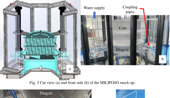
Fig. 3 Cut view (a) and front side (b) of the MILIPOSO mock-up.
Fig. 4 Bottom view of the MILIPOSO model (a) and diagrid splitting wall (b).
The figures 3 and 4 show a sketch and pictures of the MILIPOSO mock-up. Most of the components are built in optical grade transparent polymer (PMMA) in order to perform optical measurements. Indeed the velocity will be measured by laser technics such as Particle Image Velocity (PIV) or Doppler Laser Velocimetry (LDV). A plane walls external pool filled with water is put around the mock-up in order to lessen the optical deformations due to the curvature of the different components of the model. The splitting wall presented on the right hand side of the figure 4 enables to isolate one third of the mock-up to carry out the cavitation experiments. Although, as seen on the left hand side of the figure 2, the handling cask induces a dissymmetry and two configurations of the splitting wall are needed to study its influence; one configuration will include the handling cask in the studying area, the other one, don’t.
The core is located above the diagrid as seen in the figure 3. To observe the ASTRID core flow map in the four supplied zones of the mock-up (fissile, reflectors, internal storage, absorbents), diaphragms are put at the end of each supplied assembly. They aim at setting the right flow-rate by imposing a pressure loss. In each supplied zone, the flow-rate is given by the equations (5) and (6).
(5)
(6)
Where Qm is the model mass flow-rate in the supplied zone, N is the number of assemblies, Sd is the
Core
Diagrid
Water supply Coupling
pipes Diagrid Coupling pipes a b a b
Abstract No: 206 Paper No.:
diaphragm area, is the water density, d and D are the diameters of the diaphragm and the mock-up assembly, P’ is the pressure loss in the model, c is a coefficient given by the Stolz correlation which aims at taking into account the jet contraction at the outlet diaphragm. The pressure loss in the reactor can be expressed by the equation (7).
(7)
Where K’Dr stands the pressure loss coefficient, Sdr is the area of the assembly, r is the sodium density
and Qmr is the mass flow rate in the supplied zone. As the geometrical features of the assembly, the
pressure and the mass flow rate are given data of the reactor core, the theoretical value of K’Dr can be
determined. In the other hand, this pressure loss coefficient was calculated from CFD calculation performed by AREVA using StarCCM+. A slight difference occurs from the theoretical and numerical values and, to take it into account, a correction factor, defined in the equation (8), is introduced for the pressure loss in equation (5). The table 3 presents the correction factor values depending on the supplied zone. From the equation (5) and (8), we can express the diameter of the diaphragm in the equation (9). (8) (9)
Table 3. Pressure loss correction factors versus the supplied zones
Supplied zone Fissile Reflectors Internal storage Absorbents
0.95 1.00 1.03 0.97
To observe the same phenomena regarding the pressure, the similitude study is based on the Euler number. By keeping the same Euler number in the model and in the reactor, the pressure loss in the model can be calculated from the one of the reactor as shown in the equation (10).
(10)
Where P is pressure loss, L* is the scale, Qm is the mass flow-rate and is the density. Finally, the
diaphragm diameter corresponding to each supplied zone is calculated using the equations (9) and (10).
2.3 Instrumentation
In order to check to flow-rate map at the outlet of the core and the right design of the diaphragms, two methods are implemented:
PIV measurements will be carried out to evaluate the flow-rate by integrating the velocity field. This method was already employed for the MICAS [4] and the DANAH [7] mock-ups. However, the measurement errors are rather high, within the range of 1 to 5% depending on the location. Indeed, as the PIV is based on imaging technics, the measurement quality highly depends on the optical deformation due to the index change between air, water and PMMA. Fortunately, the plane walls of the external pool lessen the deformation, but in few outlet core locations, as the measurements are unable to be performed with a perpendicular angle to the wall, some optical deformations occur.
To improve the accuracy, a flow-rate measurement based on pressure losses in the model assemblies is implemented. To avoid any influence of the inlet and outlet of the assembly, the pressure is measured at the middle of the assembly. As it is not feasible to equip all the 511 supplied assemblies with pressure sensors, 22 measurements are implemented at representative locations. Every measurement will be singly calibrated in terms of pressure
error and the one of the flowmeter used for the calibration, the accuracy is 0.3%.
In order to determine the pressure in the coupling pipes and the diagrid, 88 pressure sensors are set-up in the mock-up. As seen on the left hand side of the figure 4, in the coupling pipes, each measurement location is equipped with four pressure taps in order to assess the dissymmetry of the flow. Pressure taps at the inlet and outlet of the coupling pipes allow calculating the pressure loss. A pressure transducer with fast response time is set up near the outlet of the coupling pipes in order to assess the cavitation. The measurement of the pressure inside the diagrid is performed using the non-supplied assemblies. They aim at determining the dissymmetry of the pressure inside the diagrid.
Within the coupling pipes and at the core outlet, the velocity is measured using the PIV laser technic. As seen on the left hand side of the figure 3, a window located under the coupling pipes enables an enhanced optical access for the laser and the camera. In the diagrid location, the PIV method cannot be employed due to the numerous support columns preventing any perpendicular optical planes. Fortunately, the LDV technic does not require two optical accesses and is able to measure the velocity in the diagrid between the support columns. The measurement will be performed from the bottom of the mock-up as seen on the left hand side of the figure 4. The LDV method is based on the travel time of a particle between two Doppler interference fringes created by a laser. The use of two lasers at different wavelength allows measuring the two horizontal components of the velocity. Unfortunately, the vertical component is not measurable due to a lack of lateral optical access.
From the gas pocket study point of view, only qualitative investigations will be carried out; the draining of the gas depending on the drains configuration is be assessed using fast imaging. Different gas injection will be performed: before and inside the coupling pipes, within the diagrid.
3. CONCLUSIONS
As the numerical codes do not allow sufficient level of confidence, experiments are required to validate the design options of the diagrid and the coupling pipes. The main issues are focused on the gas pocket in the diagrid and the cavitation in the coupling pipes. For that purpose, the MILIPOSO model was designed and built to investigate both issues and gather experimental results in terms of pressure and velocity to validate the code calculations. The scale of the mock-up was calculated depending on the maximal flow rate of the PLATEAU loop and the dimensionless numbers to observe: Froude, Reynolds, and velocity. From this study, the scale 1/6th was chosen to observe the Froude number as the flow regimes are the same in the mock-up and the reactor. For the cavitation study, the velocity is kept by investigating only 1/3 of the model using a splitting wall. The mock-up is made using optical grade transparent polymer and some geometrical simplifications are carried out due to the reduced scale. In order to get the right flow map at the core outlet, diaphragms diameters were calculated and set at the outlet core. From the instrumentation point of view, the velocity will be measured using the PIV and LDV technics, as the flow rate at the core outlet will be evaluated by pressure drops and PIV measurements. The gas pockets draining will be assessed by fast imaging. The series of experiments will start by checking the right diameter of the diaphragms to observe the reactor flow map.
REFERENCES
1. “4TH-Generation Sodium-Cooled Fast Reactors - The Astrid Technological Demonstrator”, http://www.cea.fr/content/download/131897/2449556/file/4th-generation-sodium-cooled-fast-reactors.pdf (2012).
2. D. Guenadou, I. Tkatshenko, P. Aubert, “Plateau Facility in Support to Astrid and the SFR Program: An Overview of the First Mock-Up of the Astrid Upper Plenum, MICAS”, Proceedings
of the16th International Topical Meeting on Nuclear Reactor Thermal Hydraulics (NURETH16),
Abstract No: 206 Paper No.:
3. D. Guenadou, P. Aubert, V. Biscay, M. Bottin, J-P. Descamps, “Study of the Free Surface Flow in the MICAS Mock-Up in Support of the ASTRID SFR Program”, Proceedings of the 11th
International Topical Meeting on Nuclear Reactor Thermal Hydraulics, Operation and Safety (NUTHOS-11), Gyeongju, Korea, October 9-13, 2016.
4. D. Guenadou, P. Aubert, J-P. Descamps, “Flow Analysis in the Upper Plenum of the MICAS Model in Support of the ASTRID Reactor Program”, Proceedings of the17th International Topical
Meeting on Nuclear Reactor Thermal Hydraulics (NURETH17), Xi’an, China, September 3-8,
2017.
5. P. Lo Pinto et al., “The Safety orientations during ASTRID conceptual design phase”, Proceeding
of FR13, Paper CN-199-267, IAEA CN-199, Paris, France, (2013).
6. T. Sageaux, O. Bernard, N. Goreaud, “Advanced Coupling methodology for Thermal-hydraulic calculations”, Proceeding of the International Conference on Fast Reactors and Related Fuel
Cycles: Next Generation Nuclear Systems for Sustainable Development (FR17), Yekaterinburg,
Russian Federation, 26-29 June, (2017)
7. C. Galati, X. Jeanningros, L. Cachon, L. Prat and C. Gourdon, “Experimental and Numerical Validation of Flow Pattern in Compact Heat Exchanger”, Proceedings of the17th International
Topical Meeting on Nuclear Reactor Thermal Hydraulics (NURETH17), Xi’an, China, September
![Fig. 1 ASTRID reactor block. [6]](https://thumb-eu.123doks.com/thumbv2/123doknet/12988121.378965/4.892.138.581.110.529/fig-astrid-reactor-block.webp)