HAL Id: cea-02023046
https://hal-cea.archives-ouvertes.fr/cea-02023046
Submitted on 18 Feb 2019HAL is a multi-disciplinary open access
archive for the deposit and dissemination of sci-entific research documents, whether they are pub-lished or not. The documents may come from teaching and research institutions in France or abroad, or from public or private research centers.
L’archive ouverte pluridisciplinaire HAL, est destinée au dépôt et à la diffusion de documents scientifiques de niveau recherche, publiés ou non, émanant des établissements d’enseignement et de recherche français ou étrangers, des laboratoires publics ou privés.
Fukushima Daiichi debris simulant
Christophe Journeau, Justine Zanini, Emmanuel Excoffier, Véronique Testud,
Emmanuelle Brackx, Christophe Chagnot, Ioanna Doyen, Emmanuel
Porcheron, Damien Roulet
To cite this version:
Christophe Journeau, Justine Zanini, Emmanuel Excoffier, Véronique Testud, Emmanuelle Brackx, et al.. Aerosols released during the laser cutting of a Fukushima Daiichi debris simulant. The 9TH European Review Meeting on Severe Accident Research (ERMSAR2019), Mar 2019, Prague, Czech Republic. �cea-02023046�
AEROSOLS RELEASED DURING THE LASER CUTTING OF
A FUKUSHIMA DAIICHI DEBRIS SIMULANT
Christophe Journeau, Justine Zanini
CEA
Cadarache, DTN, SMTA, LEAG, 13108 St Paul lez Durance, France
;
christophe.journeau@cea.fr
Emmanuel Excoffier, Véronique Testud, Emmanuelle Brackx
CEA
Marcoule, DMRC, SA2I, LMAC, BP 17171, 30207 Bagnols-sur-Cèze Cedex, France
emmanuel.excoffier@cea.fr
;
veronique.testud@cea.fr
;
emmanuelle.brackx@cea.fr
Christophe Chagnot, Ioanna Doyen
CEA
Paris-Saclay, DM2S, SEMT, LTA, 91191 Gif-sur-Yvette Cedex, France
christophe.chagnot@cea.fr
;
ionna.doyen@cea.fr
Emmanuel Porcheron
Institut de Radioprotection et de Sûreté Nucléaire (IRSN),
PSN-RES, SCA, 91192 Gif-Sur-Yvette, France
emmanuel.porcheron@irsn.fr
Damien Roulet
ONET Technologies
Engineering Business Unit, 26700, Pierrelatte, France
rouletd@onet.fr
ABSTRACT
One of the important challenges for the decommissioning of the damaged reactors of the Fukushima Daiichi Nuclear Power Plant is the safe retrieval of the fuel debris or corium. It is especially primordial to investigate the cutting conditions for air configuration and for underwater configuration at different water levels. Concerning the cutting techniques, the laser technique is well adapted to the cutting of expected material such as corium that has an irregular shape and heterogeneous composition. A French consortium (ONET Technologies, CEA and IRSN) is being subsidized by the Japanese government to implement R&D related to the laser cutting of Fukushima Daiichi fuel debris and related to dust collection technology. Debris simulant have been manufactured in the PLINIUS platform to represent Molten Core Concrete Interaction as estimated from Fukushima Daiichi calculations. In this simulant, uranium is replaced by hafnium and the major fission products have been replaced by their natural isotopes. During laser cutting experiments in the DELIA facility, aerosols have been collected thanks to filters and impactors. The collected aerosols have been analyzed. Both chemical analysis (dissolution + ICP MS and ICP AES) and microscopic analyses (SEM EDS) will be presented and discussed. These data provide insights on the expected dust releases during cutting and can be converted to provide radioactivity estimates. They have also been successfully compared to thermodynamic calculations with the NUCLEA database.
KEYWORDS
Fukushima Daiichi, Aerosols, Debris cutting, Fission Product simulants
1. INTRODUCTION
The 2018 Technical Strategic Plan for decommissioning of the Fukushima Daiichi (1F) Nuclear Power Station [1] indicates that the policy on Fukushima Daiichi fuel debris retrieval will “combine optimum retrieval methods suitable for the part of each unit where fuel debris is expected to be present, instead of making an assumption that all the fuel debris is to be taken out using a single method”. Cutting fuel debris (solidified corium) is an important issue and several techniques including mechanical and thermal cutting are being studied for (see e.g. 2, 3). The laser technique is well adapted to the cutting of corium which has an irregular shape and heterogeneous composition. In addition, the laser cutting technique induces the lowest material mass removed and the lowest mass of re-suspended aerosol during the cutting, comparatively to others cutting techniques (grinder, plasma torch, arc air, arc saw, reciprocating saw) [4]. Several R&D projects have therefore been launched and subsidized by the Japanese government to study potential techniques. In this framework, a French consortium (ONET Technologies, CEA and IRSN) has been selected among others to implement R&D related to the laser cutting of 1F fuel debris and related dust collection technology [5].
Asides from experimental optimization of the laser-cutting technique on commercially-available samples such as electrofused zirconia, steel and zirconium plates, one specificity of our approach is to have specifically fabricated simulant of Fukushima-Daiichi fuel debris [6] that have in a second part been subjected to laser cutting in our facility while aerosol production [7] has been analyzed. As the laser cutting experimental works could not be carried out at this stage in a laboratory were uranium can be manipulated, a simulant corium debris has been manufactured based on hafnium oxide while the fission products were replaced by the same elements but with their natural isotopic composition [8].
In a first section the experiments will be described. Then, the aerosols analyses will be presented. Finally, thermodynamic calculations will be presented and compared with experimental results.
2. EXPERIMENTS
2.1. Corium Debris Simulant Manufacture
The ex-vessel debris simulant has been fabricated at PLINIUS platform during the test VF-03(Vulcano Fukushima test number 3) [6]. It simulates a debris from interaction between the molten core and the concrete in the sump of Fukushima Daiichi Unit 1 (1F1) based on the MAAP LP case in Robb et al. [9] modelling of MCCI taking into account the Fukushima Daiichi concrete composition reported by Kitagaki et al. [10] and the fission product composition 10 years after shutdown from Nishihara [11].
To facilitate cutting and avoid radioactive releases, hafnium has been chosen as for uranium and plutonium has been replaced by cerium because their thermal properties are close. The replacement of uranium by hafnium has been made with respect to the assessment of the efficiency of thermal cutting by laser: indeed, uranium and hafnium dioxides have similar melting temperatures and thermal properties [8]. Unfortunately, it has not been possible to find a good simulant of uranium regarding the volatilization of oxides. Capriotti et al. [12] have shown that “many similarities exist between the system Pu-O and the system Ce-O, even in the very high temperature behavior” and that “CeO2 displays … a melting behaviour which has been recently proven to be typical of other similar metal-oxygen systems such as
Ca-O, Np-O and Pu-O”. Therefore cerium has been used in this work as surrogate of plutonium. Ruthenium has also been removed because of its chemical toxicity in oxidizing conditions and rhodium because of its cost.
The ex-vessel fuel debris are made from:
Fuel (uranium + non-volatilized fission products),
Zircalloy (Zr + Sn)oxidized at a level depending on the unit accident scenario,
Steel (containing 10.2 wt% Cr and 5.1wt% Ni) coming from the vessel internals, the vessel and concrete reinforcement bars ,
Concrete decomposition products (SiO2, Al2O3, CaO...) and oxygen from concrete water.
Table 1 lists in details the materials which has been introduced in the load. Steel has been introduced as steel balls while the other elements have been introduced as powders. After melting, two phases have segregated: a small heavier metallic phase and an oxidic debris.
Table I: Ex-vessel simulant load composition (in g per 10 kg) [6]
For 10 000 g wt% For 10 000 g wt% HfO2 2 036.62 g 20.366% Fe2O3 286.37 g 2.864% CeO2 18.47 g 0.185% Nd2O3 8.93 g 0.089% ZrO2 1 240.32 g 12.403% MoO2 8.46 g 0.085% SnO 15.80 g 0.158% Cs2O 5.04 g 0.050% B4C 17.36 g 0.174% Ba 3.33 g 0.033% Cr2O3 58.11 g 0.581% La2O3 2.66 g 0.027% Fe 630.09 g 6.301% PdO 2.55 g 0.026% FeO 1 177.76 g 11.778% Pr2O3 2.45 g 0.024% Ni 52.04 g 0.520% Sm2O3 1.83 g 0.018% SiO2 3 039.51 g 30.395% Sr 1.47 g 0.015% Al2O3 758.62 g 7.586% Y2O3 1.15 g 0.012%
2.2. Aerosol Collection during Laser-Cutting of the Fuel Debris Simulant
Laser-cutting of this MCCI oxidic debris simulant (Figure 1) has been performed in air at CEA DELIA laser shot unit of the ALTEA platform (Figure 2 left). A Trumpf 8002-type 1030-nm laser souce with continuous power of 8 kW is connected by optical fibers to CEA laser head . Two comporessed air jet flows are provided, one around the laser head and one at 45° from the corium surface. The laser cutting has been conducted in air as well as under various depths of water.
Aerosol characterization is carried out through the measurements of the mass concentration, the particle size distribution and the composition of the aerosols that is sampled in the aerosol test section connected to exhaust line of the DELIA laser cutting cell [7]. Different instruments are implemented on the aerosol
test section to provide together real time and integrated measurements of aerosol characteristics (Figure 2 right).
Figure 1: View of partially cut fuel debris simulant (in its ceramic crucible)
Figure 2: Sketch of the DELIA facility [7] Left: overall view – Right: Aerosol collection systems
2.3. Aerosol Collection and Analyses
The quartz filters (Figure 3 left) used for the global mass concentration measurement have been analyzed to determine the aerosol chemical composition (corresponding to the 30 nm-10 µm range). After the retrieval of the particle deposits and dissolution of the material (Figure 3 right), the remaining solutions were analyzed by means of ICP-MS and ICP-AES techniques depending on the elements to be measured.
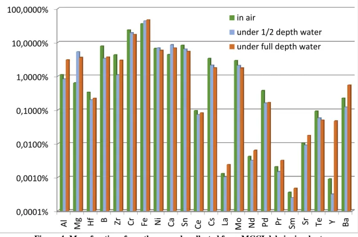
Results of the chemical analysis are presented in
Figure 4 for three test conditions: one in air, two
underwater with different pool heights above the sample. Results are expressed in terms of relative masses of each element considered in the analyzed samples.For instance, for the case in air, the major constituents of the resuspended aerosols are iron (36 wt%), chromium (23 wt%), tin (8 wt%), boron (8 wt%), nickel (7 wt%), zirconium and calcium (4 wt%), caesium and molybdenum (both 3 wt%). Uncertainties of 1/10th of the measured concentration are estimated on these measurements. As the filter is made of quartz, it is not possible to measure the fraction of silicon in the collected aerosols. From the analysis of the aerosols collected on impactors, silicon represents 17 to 33 wt% of the aerosols depending on the test configuration.
Figure 3 : Aerosol filter from VF03 laser cutting before and after solubilization
Figure 4: Mass fractions from the aerosols collected from MCCI debris simulant
0,0001%
0,0010%
0,0100%
0,1000%
1,0000%
10,0000%
100,0000%
Al
Mg
Hf
B
Zr
Cr
Fe
Ni
Ca
Sn
Ce
Cs
La
Mo
Nd
Pd
Pr
Sm
Sr
Te
Y
Ba
in air
under 1/2 depth water
under full depth water
3. MODELLING
The modelling is made under the assumption that the aerosols are formed from the condensation
of the vapors produced by the fuel debris when it is heated by the laser beam. Thermodynamic
equilibrium calculations have been carried out using GEMINI2 and the NUCLEA14 database
[11].
These calculation assume that the molten material is at a homogeneous temperature which is
fitted with experimental results. Oxygen and Argon are added to represent air. The element
Argon was used as surrogate for the nitrogen in the air. In other terms, the effect of nitride is
neglected. Some elements has been substituted by others because they are not present in the
database:
Zirconium replaces, mole by mole, Hafnium,
Chromium replaces Molybdenum,
Lanthanum is surrogate for Praseodymium, Cerium, Yttrium, Samarium, Neodymium
Silver replaces Tellurium and Palladium,
Indium is simulating Tin.
The composition of the oxidic debris simulant has been determined from the load composition
(Table I) and from measured compositions of samples from the oxide, metal and aerosols
produced during the melting phase. Table 5 presents the load in grams for each element from the
database in the cases considered for calculation. It corresponds to 8.2 kg of oxidic debris with
1.44 kg of air (1.2 m
3at 298 K; 15 wt%). This quantity of air has been determined by trial and
error in order to best fit the measured composition for the major elements. For this composition,
the liquidus temperature has been computed to be around 1980 K
Table II: Composition used for calculations of the ex-vessel oxidic simulant in air
Element Mass (g)
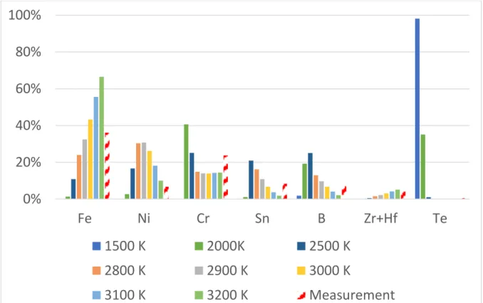
Zr 1628.16 Fe 1336.96 Si 1284.73 Ca 242.46 Al 359.64 Cr 246.96 Ba 2.67 Ni 49.29 La 25.88 In 8 Ag 0.06 B 10.03 Sr 1.44 Ar 1600 O 3208.00Figure 5 shows the measured proportions of the major elements. The major element is iron
followed by chromium tin and boron. Proportions in the vapor phase from thermodynamic
equilibrium calculations at various temperatures are also plotted. At low temperatures (1500 K),
silver (representing tellurium) is almost the only vapor. At higher temperatures (2500-3000 K)
iron, chromium nickel, boron and indium have important contributions. Assuming equilibrium at
2800-2900 K (800-900 K above liquidus) provides a reasonable correspondence between
calculation and experiment, except for Ni which is overestimated in these calculations. The major
computed vapor phases at 2800 K are BO
2(5 mbar), SiO (3 mbar), Ni (2 mbar), CrO
2(1 mbar),
B
2O
3(1 mbar) and FeO (1 mbar).
Figure 5: Mass fractions of the major constituents of the aerosols: Calculations vs measurements In stands for Sn, Ag for Te, Zr for Zr and Hf.
0%
20%
40%
60%
80%
100%
Fe
Ni
Cr
Sn
B
Zr+Hf
Te
1500 K
2000K
2500 K
2800 K
2900 K
3000 K
3100 K
3200 K
Measurement
Figure 6: Mass fractions of the minor constituents of aerosols: Calculations vs measurements Zr stands for Hf and Zr, Ag for Te, La for all lanthanides
For the less volatile elements, Figure 6 compares computations and measurements. There is a
clear underestimation of the released fraction of lanthanide, barium and strontium. This is only
marginally modified by modifying the calculation temperature. Modification of the quantity of air
in equilibrium with the heated fuel debris simulant (Figure 7) was also not able to sufficiently
increase the fraction of these elements while it affected the ratios of the major components. Even
though these fission product elements contribute to only 11 wt% of the aerosols, they carry most
of its radioactivity. Further work is thus necessary.
The effect of the replacement of uranium by hafnium (or zirconium) has also been evaluated.
Figure 8 presents two calculations for which the unique difference is that each mole of uranium
has been replaced by a mole of zirconium (representing hafnium). Uranium becomes the major
element of the vapour phase and with a 50-times increase in the computed mass fraction. The
major uranium-bearing gas species is uranium trioxide (with a vapour pressure of 23 mbar),
uranium dioxide being much less present (0.5 mbar), whereas only dioxide is indeed present for
the composition with hafnium. Indeed, uranium dioxide is known to have an important
non-congruent evaporation [15] leading in this case to the release of gaseous UO
3.
Being the major element of vapour phase, uranium-containing vapours also affects the releases of
other elements, not only by modifying the total vapour mass fraction): for instance computed
Lanthanide and Barium releases are divided by 3, while Boron releases are divided by 6. On the
opposite, mass fractions of Nickel and Tellurium (modelled by Silver) do not significantly vary
between these two calculations. As there are still large uncertainties on these calculations and no
experiments on which to compare them, it is therefore recommended to conduct cutting tests on
prototypic fuel debris simulants containing (depleted) uranium dioxide to confirm or infirm these
1,E-06
1,E-05
1,E-04
1,E-03
1,E-02
1,E-01
Zr+Hf
Te
AL
LA
BA
CA
SR
2800 K
2900 K
3000 K
Measurement
results. An intermediate first test could be to collect and analyse aerosols above pools of molten
fuel debris simulants with uranium or hafnium at 2800 K.
Figure 7: Effect of mass fraction of air in equilibrium with fuel debris simulant on the mass fraction of low volatility elements in the vapour phase (excluding Ar, O and Si)
Figure 8: Effect of uranium on the aerosol composition (mass fractions)
1,E-06
1,E-05
1,E-04
1,E-03
1,E-02
1,E-01
1,E+00
AG
AL
BA
CA
LA
SR
ZR
0%
4%
9%
12%
16%
19%
22%
25%
27%
30%
32%
Measurement
1,E-06 1,E-05 1,E-04 1,E-03 1,E-02 1,E-01 1,E+00 U FE NI CR IN B ZR AG AL LA BA CA SR4. CONCLUSIONS
In order to develop a safe laser-cutting technology for the retrieval of Fukushima Daiichi fuel debris, simulant fuel debris materials have been manufacture at CEA Cadarache and laser-cut at CEA Saclay. The emitted aerosols have been collected thanks to quartz filters which have been analyzed by ICP-AES and ICP-MS after dissolution at CEA Marcoule.
For a Molten Core Concrete Interaction simulant block cut in air, the major constituents of the aerosols are iron, chromium, silicon, tin, boron and nickel. Radioelements appear in much lower proportions.
Thermodynamic equilibrium calculations indicate that the major element proportions found in the aerosols approximately correspond to the fractions in the vapor in equilibrium with the molten fuel debris simulant at a temperature of about 2800 K. It must be stated that the collected fractions of the medium and low volatility elements (tellurium, lanthanides, strontium, barium) are larger than those computed with this equilibrium calculation, even when the temperature or the quantity of air in interaction with the melt is varied.
Another result of these calculations is the fact that uranium is expected to release much more vapor (that will later form aerosols) than hafnium while hafnium dioxide was used as simulant of uranium dioxide for its physical properties. This is linked to the important non-congruent evaporation of UO2 [15]. It is thus recommended to complement the presented results with new experiments on prototypic fuel debris simulants containing (depleted) uranium dioxide.
ACKNOWLEDGMENTS
This work has been carried out thanks to the subsidized project of Decommissioning and Contaminated Water Management (Advancement of Fundamental Technologies for Retrieval of Fuel Debris and Internal Structures) funded by the Japanese Ministry of Economy, Trade and Industry (METI) and managed by the Mitsubishi Research Institute (MRI).
REFERENCES
1. NDF, Technical Strategic Plan 2018 for Decommissioning of the Fukushima Daiichi Nuclear
Power
Station
of
Tokyo
Electric
Power
Company
Holdings,
Inc.,
http://www.dd.ndf.go.jp/en/strategic-plan/index2018.html, Nuclear Damage Compensation
and Decommissioning Facilitation Corporation, Tokyo, Japan (2018).
2. M. Tezuka, Y. Nakamura, H. Iwai, K. Sano, Y. Fukui, “The development of thermal and
mechanical cutting technology for the dismantlement of the internal core of Fukushima
Daiichi NPS”, J. Nucl. Sci. Technol. 51, pp. 1054-1058 (2014).
3. K. Yano, T. Kitagaki, H. Ikeuchi , R. Wakui, H. Higushi, N. Kaji, K. Koizumi, T. Washiya, “Direction on characterization of fuel debris for defueling process in Fukushima Daiichi Nuclear Power Station”, Proc. GLOBAL 2013: International Nuclear Fuel Cycle Conference, Salt Lake City, UT, United States, Sept 29- Oct 3 (2013).
4. G.Pilot, S. Fauvel, X. Gosse, G. de Dinechin, D. Vernhet, “Measurement of secondary emissions during laser cutting of steel equipments”, Nucl. Eng. Des. 238, pp. 2124–2134 (2008).
5. C. George, D. Roulet, C. Chagnot, C. Journeau, G. Canneau, S. Blanchard, E. Porcheron, “Benefits from developments in the field of Decommissioning for Fukushima Daiichi fuel debris retrieval: Remote-Controlled Laser Cutting Process”, Proc. WM2017 Conference, Phoenix, AZ, United States, March 6- 9 (2017).
6. C Journeau, J Monneris, B Tormos, L Brissonneau, E Excoffier, V Testud, C Chagnot, D Roulet, “Fabricating Fukushima Daiichi in-vessel and ex-vessel fuel debris simulants for the development and qualification of laser cutting technique”, Proc. ERMSAR-2017 (Eur. Rev. Mtg Sev. Accident Res.), Warsaw, Poland, May 16-18 (2017).
7. E. Porcheron, S. Peillon, T. Gelain, C. Chagnot, C. Journeau, D. Roulet, “Analysis of aerosol emission and dispersion during the laser cutting of Fukushima fuel debris simulants”, Proc. ICONE 26 (26th Int. Conf. Nucl. Eng., London, England, July 22-26 (2018).
8. C. Journeau, D. Roulet, E. Porcheron, P. Piluso, C. Chagnot, “Fukushima Daiichi fuel debris simulant materials for the development of cutting and collection technologies”, J. Nucl. Sci. Technol., 55, pp. 985-995 (2018).
9. K. Robb, M.W. Francis, M. T. Farmer, Ex-Vessel Core Melt Modeling Comparison between MELTSPREAD-CORQUENCH and MELCOR 2.1, Oak Ridge National Lab report ORNL/TM-2014/1 (2014).
10. T. Kitagaki, K. Yano, T. Washiya, “Research Approach of MCCI products characterization for debris removal”, Poster ID IAEA-CN-235-85, IEM on Strengthening Research and Development Effectiveness in the Light of the Accident at the Fukushima Daiichi Nuclear Power Plant, IAEA Headquarters, Vienna, Austria, February (2015).
11. K. Nishihara, H. Iwamoto, K. Suyama, Estimation of Fuel Compositions in Fukushima-Daiichi Nuclear Power Plant, JAEA Report JAEA-Data/Code 2012-018 (2012).
12. L. Capriotti, A. Quaini, R. Böhler, K. Boboridis, L. Luzzi, D. Manara, “A laser heating study of CeO2 solid/liquid transition: challenges related to a refractory compound with a very high oxygen pressure”. High Temp. High Press. 44: 69-82 (2014).
13. E. Porcheron, S. Peillon, T. Gelain, C. Chagnot, C. Journeau, E. Excoffier, V. Testud, D. Roulet, “Fukushima Dai-ichi fuel debris retrieval: analysis of aerosol emission and dispersion during simulants laser cutting”, Proc. DEM-2018 InT; Conf. Dismantling Challenges, Avignon, Oct. 22-24 (2018).
14. S Bakardjieva, M Barrachin, Sevostian Bechta, D Bottomley, L Brissoneau, B Cheynet, E Fischer, C Journeau, M Kiselova, L Mezentseva, et al. Improvement of the European thermodynamic database NUCLEA. Progress in Nuclear Energy, 52(1), pp.84–96 (2010).
15. M. Brykin, M. Sheindlin, Calculation of vapor composition produced by incongruent laser vaporization of uranium dioxide in vacuum, High Temp.-High Press., 43, pp. 101-113 (2014).

![Figure 2: Sketch of the DELIA facility [7] Left: overall view – Right: Aerosol collection systems](https://thumb-eu.123doks.com/thumbv2/123doknet/13011698.380666/5.918.133.795.544.756/figure-sketch-delia-facility-overall-aerosol-collection-systems.webp)