HAL Id: hal-00077852
https://hal.archives-ouvertes.fr/hal-00077852
Submitted on 2 Jun 2006HAL is a multi-disciplinary open access archive for the deposit and dissemination of sci-entific research documents, whether they are pub-lished or not. The documents may come from teaching and research institutions in France or abroad, or from public or private research centers.
L’archive ouverte pluridisciplinaire HAL, est destinée au dépôt et à la diffusion de documents scientifiques de niveau recherche, publiés ou non, émanant des établissements d’enseignement et de recherche français ou étrangers, des laboratoires publics ou privés.
systems
Youssef Nasser, Mathieu Des Noes, Laurent Ros, Geneviève Jourdain
To cite this version:
Youssef Nasser, Mathieu Des Noes, Laurent Ros, Geneviève Jourdain. The effect of clock frequency off-set on OFDM-CDMA systems. Symposium on Communications and Vehicular Technology (SCVT’05), 2005, Enschede, Netherlands. �hal-00077852�
The Effect of Clock Frequency Offset on OFDM-CDMA
systems
Youssef Nasser
(*
), Mathieu des Noes
(*
), Laurent Ros
(†
), Geneviève Jourdain
(†
)*Commissariat à l’Energie Atomique, 17 rue des Martyrs, 38054 Grenoble France †Laboratoire des Images et des Signaux, INPG, 46 Av. Felix Viallet, 38031 Grenoble France
Contact: [email protected], [email protected]
I. Introduction
Recently, Orthogonal Frequency and Code Division Multiplexing (OFCDM) access technology has been investigated for the next generation of mobile communication systems [1]. A known drawback of these multi carrier systems is their sensitivity to synchronization errors [2] Particularly when the transmitter and receiver sampling frequencies are not perfectly synchronized, Inter Carrier Interference (ICI) is generated, which degrades the SINR at the receiving side. The contribution of this article is twofold. First, a generalized framework is proposed for modelling the effect of clock frequency offset on 2 dimensional spreading OFDM-CDMA systems [1]. Then, exploiting some results from the random matrix theory, an analytic expression of the Signal to Interference and Noise Ratio (SINR), modelling the impact of clock frequency offset, is derived. This formula is independent from the actual values of the spreading codes while taking into account their orthogonality. This is the novelty of this article. This model works for frequency selective channels and any single user detector.
II. System
description
Figure 1
shows a 2 dimensional (2D) spreading OFDM-CDMA [6] transmitter/receiver chain for a downlink communication with Nu users.Sp re ad in g Scra m bl in g 2D c hip m ap pi ng IF FT In se rt ion C P D/ A ( T ) A/ D ( Tr ) channel Su pp re si on C P FF T Ch an ne l es ti m ati on , Eq ua liz at er 2D c hi p de m ap pin g De sc ra m blin g De sp re ad in g SINR estimation a0(s) aNu-1(s) (s) 1 u N aˆ − (s) 0 aˆ Sp re ad in g Scra m bl in g 2D c hip m ap pi ng IF FT In se rt ion C P D/ A ( T ) A/ D ( Tr ) channel Su pp re si on C P FF T Ch an ne l es ti m ati on , Eq ua liz at er 2D c hi p de m ap pin g De sc ra m blin g De sp re ad in g SINR estimation a0(s) aNu-1(s) (s) 1 u N aˆ − (s) 0 aˆ
Figure 1: OFDM-CDMA transmitter.
Each symbol am(s) of the mth user is first spread by a Walsh-Hadamard sequence of Nc chips, and
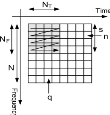
scrambled by a cell specific long pseudo random sequence. The resulting samples are then allocated on the time/frequency grid as shown on Figure 2 [1].
Freque nc y NT NF N q s n Time
Figure 2: 2D spreading scheme.
The spreading factor is thus Nc= NF×NT where NF and NT are respectively the frequency and time
domain spreading factors. Assuming a FFT of N points, each user transmits S=N/NF data symbols
in an OFDM-CDMA block. Eventually, the signal at the IFFT input is:
(
)
1
,...,
0
,
1
,...,
0
;
1
,...,
0
]
[
)
(
1 0 ,−
=
−
=
−
=
+
=
+
∑
− = F T N m T s m m m F qN
n
S
s
N
q
q
nN
c
s
a
P
n
sN
b
u (1)s is the index referring to the sub-band of NF adjacent sub-carriers used for the transmission of the
symbol ai,m(s). Pm is the power of the mth user which is supposed constant for all sub-bands and
cm,s represents its spreading sequence composed from the chip by chip multiplication of the user
assigned Walsh-Hadamard sequence and the cell specific scrambling code. At the output of the IFFT and after the cyclic prefix insertion (ν samples), the signal is passed through a multipath channel with delay spread Wand corrupted by a complex value Additive White Gaussian Noise (AWGN) with varianceσ2.
Without loss of generality, we assume at the receiving side, that one is interested by the symbols of user 0. In order to write the received signal with matrix-vector notation, the following matrices are defined: P = diag(P0,…, PNu-1) is the NuxNu diagonal matrix which entries are the powers
allocated to each code, Q = diag(P1,…,PNu-1) is the (Nu-1)x(Nu-1) diagonal matrix containing the
powers of the interfering codes, C[s] = (C0[s], C1[s],…, CNu-1[s]) is the NcxNu matrix containing
all the spreading codes used in the sth sub-band and U[s] = (C
1[s],…, CNu-1[s]) is the Nc x (Nu-1)
matrix containing the interfering codes used in the sth sub-band. C[s] and U[s] are isometric
matrices, and depend on sub-band index s because of the long scrambling code. We also define the vectors
[ ]
(
)
TN s a s a s a = 0( ),..., u−1() and a
[ ]
s(
a (s),..., aNu (s))
T ~ 1 1 − = correspondingrespectively to the symbols of all users and interfering users transmitted in the sth sub-band.
At the receiver side, after FFT operation, the signal on each carrier is multiplied by the one-tap equalizer coefficient zq(wNF +p) which compensates for channel attenuation and signal rotation due to timing error. The output is then descrambled and despread. The estimated symbol on the sub-band w is [6]:
[ ]
[ ]
[ ]
[ ]
[ ]
[ ]
[ ]
[ ]
[ ]
( ) ( ) ) , ( ) ( ~ ) , ( ) ( ) ( ) , ( ) ( ) ( ˆ 0 3 1 0 0 2 0 1 0 0 0 0 0 3 2 1 0 0 w N w Z w C I s a P s C s w B w Z w C I w a Q w U w w B w Z w C I w a w C w w B w Z w C P I I I I I w a H S w s s H H H = = = = + + + =∑
− ≠ = (2)I0 represents the useful signal, I1 the Multiple Access Interference (MAI) generated in the same
sub band w, I2 the interference generated by all users from other sub-bands and I3 the filtered
noise. H(w,s) is a Nc×Nc matrix modeling the combined effect of channel attenuation and clock
frequency offset. It is defined by:
− − − − − = ) 1 , 1 ( ) 0 , 1 ( ) 1 , 1 ( ) 0 , 1 ( ) 1 , 0 ( ) 0 , 0 ( ) , ( , , , , , , F F s w F s w F s w s w F s w s w N N A N A N A A N A A s w H L L M O M M O L L − = ) 1 , , , , ( 0 0 0 0 0 0 ) 0 , , , , ( ) , ( , T s w N n p s w n p s w n p A φ φ L O O M M O O L
φ(w,s,p,n,q) is the equivalent channel transfer function including the effect of the clock frequency offset [4]: + ∆ + − + − − × + + ∆ × + ∆ + − + − + = N n p N s w T T N n sN e N j T T N n sN e v N q j N n p N s w T T N n sN e n sN e h q n p s w F F F F F N F ) ( ) ( ) ( ) 1 ( exp ) ( ) ( 2 exp ) ( ) ( ) ( )) ( ( ) , , , , ( π π ψ φ (3)
h(l) is the lth output of the FFT of the channel impulse response ,Ψ
N(x) is the function defined by
( )
) sin( ) sin( x N Nx x N π πψ = and e(n) is the function defined by e(n)=n if n≤N/2 and e(n)=n-N if n≥N/2. Z(w) is a Nc×Nc diagonal matrix which components are the equalizer‘s coefficients
III. Asymptotic Performance
The symbols am(s) are assumed i.i.d. zero mean variance random variables with unit variance. The
SINR is deduced from (2) by calculating the expectations of I0, I1, I2 and I3:
2 3 2 2 2 1 2 0 I E I E I E I E SINR + + = (4) with
[ ]
[ ]
[ ]
[ ]
[ ]
[ ]
[ ]
[ ] [ ]
[ ]
(
H)
c S w s s H H H H H H H H H H H w Z w Z tr N I E w C w Z s w H s PC s C s w H w Z w C I E w C w Z w w H w QU w U w w H w Z w C I E w C w w H w Z w C P I E ) ( ) ( ) ( ) , ( ) , ( ) ( ) ( ) , ( ) , ( ) ( ) , ( ) ( 2 2 3 1 0 0 0 2 2 0 0 2 1 2 0 0 0 2 0 σ = = = =∑
− ≠ = (5)These expressions show that the SINR depends of actual value of the spreading codes. Hence (5)
cannot be used practically due to its complexity and its sensitivity to the code allocation. In order to evaluate the different terms of (5) independently on the spreading codes, we use three properties
A- If 1 ( (0),...., ( 1)) − = m m c c m c c N N
C where cm(l)’s are iid complex random variances with zero mean, unit variance and finite eighth order moment and A is a Nc×Nc uniformly bounded deterministic
matrix (independent of Cm) then [7]:
) ( 1 A tr N AC C c N m H m c→∞→ (6)
B- Let C a Haar distributed unitary matrix of size Nc×Nc. C can be decomposed into a vector
0
C of size Nc and another matrix U of size Nc×Nu-1 as C = (C0,U), thus [8]:
(
H)
c N H C C I P UQU →→∞ α − 0 0 (7)C- If C is generated from a Nc×Nc Haar unitary random matrix then matrices CPCH and ZHHHHZ
are asymptotically free almost everywhere [9], one concludes
(
)
(
)
(
H)
c H H c N H H H c CPC tr N Z ZHH tr N Z H ZHCPC tr N c 1 1 1 → × ∞ → (8)As was already explained in [5], the Haar distributed assumption is only technical. The final results obtained with real spreading matrices match with the model prediction. Invoking the properties (6), (7) and (8), the expectation terms of (5) simplifies as follows:
( )
(
)
( )(
)
(
H)
c S s s s H H c s c H H c s c w Z w Z tr N I E w Z s w H s w H w Z tr N P I E w w H w Z tr N w Z w w H w w H w Z tr N P I E w w H w Z tr N P I E ) ( ) ( ) ( ) , ( ) , ( ) ( ) , ( ) ( 1 ) ( ) , ( ) , ( ) ( 1 ) , ( ) ( 1 2 2 3 1 ' 0 2 2 2 2 1 2 0 2 0 σ α α = = − = =∑
− ≠ = (9)α=Nu/Nc is the system load and
∑
−= − = 1 1 1 1 Nu m m u P N
P is the average power of the interfering users.
In order to validate the asymptotic SINR evaluated with (9), we first compare its results with
Monte Carlo simulations. The common simulations assumptions are: FFT size: N=64, the scrambling sequence is the concatenation of 19 Gold sequences of 128 chips, constellation: QPSK.
Figure 3 illustrates the comparison between theoretical and simulated SINRs of the fifth band (s=5) for an OFDM-CDMA system (NF×NT=8×4), a BRAN A channel model and a MMSE
equalizer ( ( ( ) ) γ φ φ + = + * 2 , , , , , , , , ) ( q p p w w q p p w w p wN zq F , 2 σ α
γ = P ). It shows that our theoretical model matches perfectly with simulations, even for a relatively small spreading factor (Nc=32).
-5 0 5 10 15 20 25 0,001 0,01 0,1 1 N∆T/Ts Asymp Eb _ N0 =10 d B Asymp Eb _ N0 =2 0 d B Sim Eb _ N0 =10 d B Sim Eb _ N0 =2 0 d B
Since, the asymptotical model has been validated, we will exploit some induced results to give more insights about the comparison of the different spreading schemes. We define then the SINR
degradation of the system defined in dB by
= SINR SINR Deg dB max 10 )
( 10*log where SINRmax is the
SINR obtained without clock frequency offset. Figure 4 shows that the MC-CDMA scheme (NF×NT=32×1) is slightly less sensitive than OFDM-CDMA (NF×NT=8×4) and MC-DS-CDMA
(NF×NT=1×32) systems to clock frequency offset. Moreover, it shows that for a given signal
bandwidth, this sensitivity increases with the system load and number of carriers.
1,00E-05 1,00E-04 1,00E-03 1,00E-02 1,00E-01 1,00E+00 0,001 0,01 0,1 N∆T/Ts D egr adation ( dB) MC-DS-CDMA Eb_N0=10dB MC-DS-CDMA Eb_N0=20dB OFDM-CDMA Eb_N0=10dB OFDM-CDMA Eb_N0=20dB MC-CDMA Eb_N0=10dB MC-CDMA Eb_N0=20dB
Figure 4: Degradation of spreading schemes (Bran A channel Eb/N0=20dB).
Let us give some more insights about the comparison between MC-CDMA (NF= N, NT=1, S=1)
and MC-DS-CDMA (NF=1, NT=N, S=N) schemes. In order to compare the different spreading
schemes, we define the parameter:I(w)=EI1 2+EI2 2+EI3 2. Let us note IMC-DS-CDMA(w) the
interference power of the wth sub-carrier of the MC-DS-CDMA scheme, and I
MC-CDMA the total
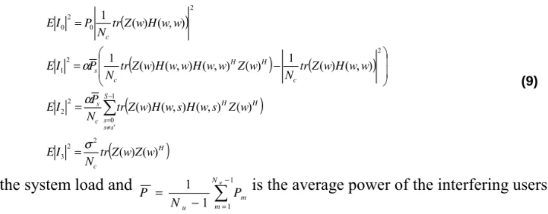
interference for a pure MC-CDMA system. For a zero-forcing (ZF) equalizer (γ=0), we show that:
∑
=− − − − = 1 0 ) ( 1 N w CDMA DS MC CDMA MC I w N I (10)With a ZF equalizer, the total interference power of a MC-CDMA system is the average value of the interference experienced by each sub-carrier in a MC-DS-CDMA system.
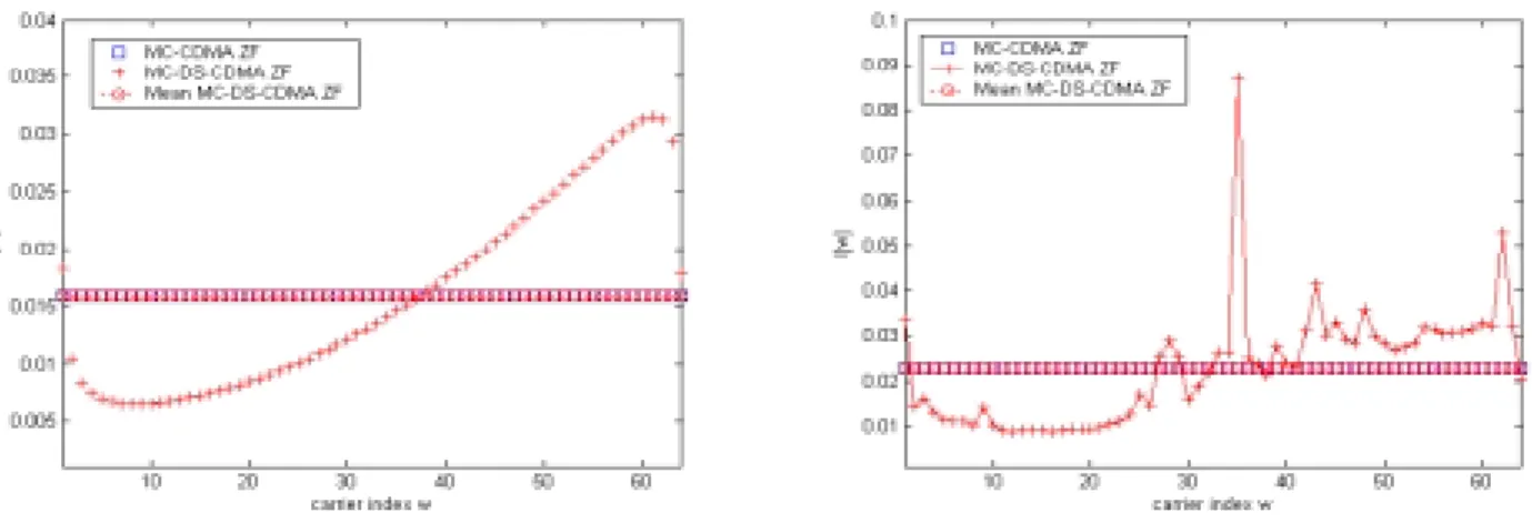
Figure 5-a and Figure 5-b show the validity of equation (10) in gaussian and BRAN A channels (Eb/No = 20 dB). The legend ‘mean MC-DS-CDMA’ refers to the interference computed with equation (10). Figure 6 shows that (10) is not valid for a MMSE equalizer in a frequency selective channel.
Figure 6: Interference power (MMSE and BRAN A channel, ∆T/T = 1560 ppm).
IV. Conclusion
In this article, we have investigated the effect of clock frequency offset on the performance of 2 dimensional OFDM-CDMA spreading schemes. A new analytical expression of the SINR has been derived. It is independent of the actual value of the spreading codes but takes their orthogonality into account. It is valid for different single user detector (MMSE, ZF) and for any frequency selective channel. Exploiting this model, we found that, for a ZF equalizer, the total interference power of a MC-CDMA system is the average of the interference experienced by each sub-carrier in a MC-DS-CDMA system whatever the channel model. The latter does not hold for a MMSE detector.
V. References
[1] N. Maeda, Y. Kishiyama, H. Atarashi and M. Sawahashi, “Variable Spreading Factor OFCDM with Two Dimensional Spreading that Prioritizes Time domain Spreading for Forward Link Broadband Wireless Access”, Proceedings of VTC spring 2003, April 2003, Jeju, Korea.
[2] T. Pollet, P. Spruyt, M. Moeneclaey, “The BER performance of OFDM systems using non-synchronized sampling”, Proceedings of Globecom 1994, vol.1, pp: 253-257.
[3] H. Steendam, M. Moeneclaey, “The effect of clock frequency offsets on downlink MC-DS-CDMA” Proceedings of ISSSTA’02, September 2002, Prague, Czech Republic.
[4] H. Steendam, M. Moeneclay, “The effect of synchronization errors on MC-CDMA performance” Proceedings of ICC’99, pp: 1510 – 1514, June 1999, Vancouver, Canada.
[5] M. Debbah, W. Hachem, P. Loubaton and M. de Courville, “MMSE analysis of Certain Large Isometric Random Precoded Systems”, IEEE Trans. on Information theory, Vol. 43, Issue: 5, May 2003.
[6] Y. Nasser, M. des Noes, L. Ros, G. Jourdain, “SINR estimation of OFDM-CDMA systems with constant timing offset: a large system analysis”, proceedings of PIMRC’05, Berlin, September 2005. [7] J. Evans, D.N.C Tse., “Large system performance of linear multiuser receivers in multipath fading
channels”, IEEE Trans. on Information theory, Vol. 46, Issue: 6, pp. 2059-2078, Sept. 2000
[8] J.M. Chaufray, W. Hachem, Ph. Loubaton. “Asymptotical Analysis of Optimum and Sub-Optimum CDMA Downlink MMSE Receivers”, IEEE Trans. on Information theory, Vol: 50, Issue: 11, Nov. 2004 pp:2620 – 2638
[9] W. Hachem, “simple polynomials for CDMA downlink transmissions on frequency selective channels” , IEEE Trans. on Information theory, Volume: 50, Issue: 1, pp: 164 – 171 Jan. 2004
![Figure 1 shows a 2 dimensional (2D) spreading OFDM-CDMA [6] transmitter/receiver chain for a downlink communication with N u users](https://thumb-eu.123doks.com/thumbv2/123doknet/13027267.381675/2.892.239.664.663.952/figure-shows-dimensional-spreading-transmitter-receiver-downlink-communication.webp)