HAL Id: hal-01303500
https://hal.archives-ouvertes.fr/hal-01303500
Submitted on 18 Apr 2016
HAL is a multi-disciplinary open access
archive for the deposit and dissemination of
sci-entific research documents, whether they are
pub-lished or not. The documents may come from
teaching and research institutions in France or
abroad, or from public or private research centers.
L’archive ouverte pluridisciplinaire HAL, est
destinée au dépôt et à la diffusion de documents
scientifiques de niveau recherche, publiés ou non,
émanant des établissements d’enseignement et de
recherche français ou étrangers, des laboratoires
publics ou privés.
Modeling and control of a piezoelectric microactuator
with proprioceptive sensing capabilities.
Roba El Khoury Moussa, Mathieu Grossard, Mehdi Boukallel, Arnaud
Hubert, Nicolas Chaillet
To cite this version:
Roba El Khoury Moussa, Mathieu Grossard, Mehdi Boukallel, Arnaud Hubert, Nicolas Chaillet.
Mod-eling and control of a piezoelectric microactuator with proprioceptive sensing capabilities..
Mecha-tronics, Elsevier, 2014, 24, pp.590-604. �10.1016/j.mechatronics.2013.12.002�. �hal-01303500�
Modeling and Control of a Piezoelectric Microactuator with Proprioceptive
Sensing Capabilities
Roba El Khoury Moussa1, Mathieu Grossard1, Mehdi Boukallel2, Arnaud Hubert3, and Nicolas Chaillet3 Corresponding author: e-mail: mathieu.grossard@cea.fr, tel:+33(0)169080787, fax: +33(0)169080701
1Interactive Robotics Laboratory, LIST, CEA, Gif-sur-Yvette, F-91190, France 2Sensorial and Ambient Interfaces Laboratory, LIST, CEA, Gif-sur-Yvette, F-91190, France
3Automatic Control and Micro-Mechatronic Systems Department, FEMTO-ST Institute, Université de Franche-Comté, ENSMM-UTBM-CNRS, Besançon, France
Abstract
In this paper, modeling and control strategies for a new observability-optimized piezoelectric microactuator are pre-sented. The targeted applications concern mainly the design of microgripper for micromanipulation tasks. The device has been designed using a topological optimization method, which takes into account the optimal full integration of piezoelectric actuating and sensing elements within the device. It is achieved in link with modal controllability and observability considerations. The vibrational modes that govern the tip deflection of the monolithic compliant structure are proved to be fully observable by the integrated sensing area of the device. The proposed control strategy permits to simply reconstruct the deflection using electric charges measurement and modal state observer. Finally, the vibrations naturally induced by the flexible structure are successfully damped using robust and low order controller.
Keywords: Flexible structure, piezoelectric microactuator, vibration control, topological optimization.
1. Introduction
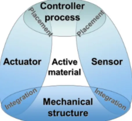
Micromanipulation tasks use mostly microgripper devices based on compliant mechanisms. These ones are mono-lithic flexible structures that transmit a motion under elastic strain. Compliant mechanisms present many advantages at the small scale: simplified manufacturing, reduced assembly costs, reduced noise, no wear, no backlash, high pre-cision, and ability to accommodate unconventional actuation schemes. One interesting type of smart material used in microrobotic applications is the piezoceramic PZT. Piezoelectric actuation has become widespread in microma-nipulation systems where high positioning accuracy is needed[1]. Beyond their appealing properties in the sense of micromechatronic design, an advantage of using piezoelectric material is its reversible electromechanical effect. This explains its high potential use in the microrobotic field as actuators and/or sensors[2, 3]. The design of smart microrobotic structures based on piezoelectric material, or more generally on active materials, is a non-intuitive task because of their multifunctional requirements (Fig. 1). This task poses the problem of the physical integration of actuators and sensors in the compliant mechanism (size, topology, . . . ), as well as their optimal placements in the full structure[4]. Indeed, these locations influence directly the performances that can be reached by the device, even if feedback or feedforward control strategies are used[5].
Many scientific works have already been done on the problem of optimally distributing piezoelectric actuating and sensing elements within flexible structures. They deal mainly with active vibration control or minimization of undesired spillover effects[6, 7, 8]. In particular, topology optimization solves the problem of distributing reference material in a design domain subjected to loading and support conditions. Although various topology optimization methods have been applied to the design of piezoelectric devices[9, 10], most of them consider the optimal distribution of passive materials while predefining the locations of piezoelectric materials. Other works are focused on the optimal design of coupling structures for piezoelectric actuator, considering maximum energy efficiency[11]. But finally, few studies deal with the optimal distribution of piezoelectric materials for the design of monolithic piezoelectric actuator using topology optimization formulation[12, 13]and even less for piezoelectric sensor design[14]. To our knowledge, no topological method have been yet used for the topological optimization of monolithic piezoelectric
Figure 1: Smart structure design.
devices with a fully integration of both actuation and sensor components. In addition, very few related works deal with topological optimization method for actuator or sensor design including frequency response analysis[12, 15]. In these related works, the generally used objective functions are based on the maximization of either geometrical advantage (stroke amplification), or mechanical advantage (force amplification), according to predefined harmonic loadings. Optimization of these active compliant micromechanisms from the first design step will strongly improve their performances if we take into account relevant criteria from the control field.
In previous works, a new compliant PZT monolithic microactuator was designed in simulation by authors[16]. Its flexible structure has been simulated and optimized using a multidisciplinary topology optimization algorithm. The software design method is based on a building block method and a genetic algorithm that optimize the passive, active and sensitive areas of the flexible structures. In this paper, the device has been prototyped and its observer-based controller is presented. In addition to purely mechanical criteria, innovative observability-based considerations are taken into account in our design. This ensures the effectiveness of the control strategies presented in the following. It relies on observability-based criteria which exploit the modal gramians properties of flexible structures[17]. A special attention has been paid on the optimal physical integration of the actuating and proprioceptive sensing areas within the structure regarding dynamic performances. Indeed, the tip displacementδ to be controlled have to be optimally reconstructed from induced charges q measurements in the sensitive structure. Finally, the strategy we proposed in this paper avoids the use of exteroceptive laser sensor normally required for accurate closed loop control of the deflection. This paper is organized as follows. In section II, we briefly review the underlying idea of the observability-based optimization strategy. It led to the specific design of the microactuator subsequently prototyped and presented in section III. In section IV, the experimental vibrational dynamics governing the tip deflection and the electric charges induced in the prototype are validated according to the optimization specifications. In section V, nonlinear phenomena are considered from the perspective of control design. We construct the complete electromechanical model of the tip deflectionδ and the electric charges q as a function of the input control voltage u. The hysteresis phenomenon in deflection is compensated using a Prandl-Ishlinskii (PI) technique and a damping cascaded controller is implemented. Finally, a modal state observer is adopted to reconstruct the dynamics of the tip deflection from the proprioceptive sensor. The control of the reconstructed tip deflection is experimentally performed.
2. Strategy for observability-based design of flexible structures
In this section, observability issues are considered together with the multiobjective optimization procedure.
2.1. Observability issues
The design of active structures with both integrated actuation and sensor capabilities is a non-intuitive task and the designer is faced with two main issues:
1. A reduced model of the structure has to be synthesized, which must include the few dominant low-frequency modes, without rejecting the residual modes that can destabilize the system (i.e. high roll-off after the dominant modes). Resonance peaks amplitudes must be maximized in the frequencies bandwidth to increase author-ity control on the dominant modes of the deflection transfer functionδ/u. On the contrary, the amplitudes of resonance peaks after cut-off frequency must be minimized to increase gain margin and to limit modes destabi-lization in this area (spillover phenomenon).
2. If all dominant modes are not well observed by the sensing area of the flexible structure, the reconstruction of the deflection ˆδ will not be guaranteed in an optimal way by the observer.
Hence, the authors propose in[16][18]a new numerical criterion, referred as Jk,thvin the following, to meet these two issues: the first problem disappears when the pseudo-optimal structure is forced to have k first dominant modes in theδ/u control transfer function Gco(s) with s the complex variable of the Laplace domain (seeFig. 2). The second
problem is overcame if we guarantee a high-level of observability of these dominant modes by means of the electric charges in the observation q/u transfer function Gob(s). This new criterion is applied to the optimal design of a new
microactuator device, and this is the core of this paper.
Figure 2: Example of desired forms for the control Gcoand observation Gobtransfer functions.
With thv a threshold value specified by the designer, the optimization procedure ensures that the k first modes dominate by at least thv times the residual modes (as seen inFig. 2). In other words, when satisfying this criterion, we privilege the modes where good observability ofδ/q operator coincides with its dominant modes.
2.2. Optimization methodology for integrated piezoelectric device
The above criteria were used with a multidisciplinary topology optimization procedure. Reader can find detailed descriptions of the building block optimization tool in[16].
This optimization tool is based on a multiobjective genetic algorithm approach, which searches the optimal dis-tribution of available building blocks. The resulting structure is thus an assembly of elementary passive, active or sensitive compliant blocks chosen from a library. Some blocks can act as pure mechanical stiffness, whereas others integrate actuation or sensing functions. The optimization problem not only takes into account the topological specifi-cations, but also an optimal set of boundary conditions (fixed frame location, contacts, end-effectors, etc), dimensions and materials, depending on some optimization criteria selected by the designer.
The library of building blocks is composed of 36 building block elements, made of beams assembly. They are sufficient to build a high variety of topologies. Moreover, the block feasibility related to fabrication process constraints
can also be taken into account during the problem specification. The blocks present some various topologies. Their advantage is that they can furnish multiple coupled DoFs, thus generating more complex movements with only one building block than a method which would have consisted in optimizing directly the location of the elementary beams of the truss-like structure. Thus, the function of the building blocks method is to save computational time during the optimization process by reducing complexity of the combinatorial of the problem. It should also be noted that calculation of the different matrices of each valued block is done one time only at the beginning of the optimal design problem (before running the genetic algorithm), which saves running time.
From the static point of view and for an applied external voltage u, the whole topology of the flexible structure is designed to maximize both the steady-state tip deflectionδ and the electric charges q on the sensing parts. In addition to these pure mechanical criteria, we consider the Jk,thvcriterion with k = 2 and thv = 3 for the pseudo-optimal design of the microactuator structure presented in this paper. This criterion enables to shape the open-loop frequency responses of both the controlled deflectionδ/u transfer operator and observed electric charges q/u transfer operator as described previously. From the topological point of view, this results in an appropriate placement of the actuating and sensing areas. Used together in a multiobjective optimization procedure, these three criteria can fully and pseudo-optimally integrate the actuation and sensor functions into the structure.
3. Presentation of the observability-optimized piezoelectric prototype
The pseudo-optimal prototyped microactuator is presented in the following. The proposed control strategy is also introduced.
3.1. Overview of the microactuator prototype
The monolithic micromechatronic prototype results from an assembly of PZT beams (Fig. 3). Either passive, active or sensitive beams inside a block-like mesh constitutes the compliant structure. It is assumed to undergo structural planar strain, mainly due to in-plan flexion. The structure topology has a maximal size of 15 mm× 18 mm, and a constant thickness of 200µm.
Figure 3: 3D CAD of the left-finger PZT microactuator with integrated sensing capabilities.
Our approach consists in integrating a voltage driven actuator and a charge measuring device for sensing. Even if other arrangements are also possible (e.g. charge driven actuation[19]), ours has been widely used in the control of flexible structures and seems to be the most straightforward way to take into account actuation and sensing in our optimized Finite Element modeling. Indeed, such a configuration enables the structural mechanical dynamics of each structure to be easily computed on-line, avoiding modification of mechanical poles locations due to specific charge driven considerations. Regarding the actuated beams, longitudinal strain is generated under the transverse electric field along the thickness, thus exploiting the transverse effect of piezoelectricity. Regarding the sensitive beams, they exploit the piezoelectric effect to generate electric charges when submitted to the strain field of the actuated flexible
structure. An electronic charge-voltage converter is then used to extract the electric charges from the sensing areas. If ideal operating mode of this electronic converter is supposed, upper and lower electrodes of the sensing piezoelectric beams are assumed short-circuited. As a consequence, the sensing piezoelectric beams are only linked to the local strain of the microactuator.
The monolithic structure can be considered as the actuator of a left-arm gripper and is made of a single piezo-electric material PIC151 from PI Piezo Ceramic Technology. This device includes either passive, active or sensitive blocks inside a 2× 3 mesh[16]. In the optimization procedure, the number of active (resp. sensitive) blocks in the structure could vary between 1 and 4. They are optimally chosen in the compliant building block library. When external voltages are applied to the blocks electrodes, the output node (tip of the structure) has to move along the
x-axis. The size ratio of the blocks can vary between 1 and 2. The boundary conditions of possibly fixed nodes are
exclusively devoted to the parts that are reported in the bottom line of the structure. When the genetic algorithm does not find any new pseudo-optimum during 200 subsequent generations (stagnation criteria), the best compromises are kept and can be found on Pareto fronts. The population size is fixed to 100 solutions, with a mutant proportion in the population of 60% and probability of genes mutation of 40%. Considering mutation process within the iterative algorithm enables to avoid locally pseudo-optimal solutions.
The whole prototyped device is laser-cut from a monolithic PIC151 piezoelectric plate with electrodes on upper and lower faces (Fig. 4).
Figure 4: Machined piezoelectric device, clamping system and electrode patterns for the actuating and sensing areas.
Actuation and sensor functions are wired separately by two independent optimized electrodes paths. When ex-ternal voltages are applied to the actuation electrodes (±100 V), the whole structure deforms to produce a motion of the output node of the structure (finger tip of the microgripper)δ along the x-axis (max ±7µm), while the sensitive electrodes generate electric charges proportional to the strain field within the structure (max 1.9 × 10⁻⁹C).
From a computational point of view, optimization criteria take advantage of the dynamic finite elements formula-tion of the flexible structure. This is rewritten as a finite-dimensional linear system :
Mη + Kη = Eu¨ yco= δ = Fη yob= q = Lη (1)
The foregoing second-order differential matrix equations represent the undamped dynamic behavior of the system, where M and K are the structure’s mass and stiffness matrices. These matrices are obtained from the finite element formulation by the assembly of the matrices of all the beams constituting the structure. Let us consider the integer
(control applied voltage on the device). The input matrix E reflects the location of the actuated DoFs, while ycois the
controlled output representing the tip displacementδ of our microgripper. The output displacement matrix F reflects therefore the node position of the output ycoamong all the p nodes of the truss-like structure. The third equation in
(1)computes the electric charges of all the sensing beams, while the output matrix L points out the placement of the piezoelectric sensing beams within the structure. In this model, it is important to emphasize that the controlled output variable ycois not directly observed, as compared with related works where yob= yco, and where the controlled tip of
the piezocantilever have to be directly measured with an exteroceptive position sensor.
3.2. Observation strategy
To highlight the advantage of the proposed observation strategy, the physical coordinate base expansion (1)is firstly transformed into the modal base to emphasize the flexible modes contribution. The harmonic solutions of the first equation in(1)give the eigenvectors matrixΨ and natural frequencies ωniof the system :
¨z+ diag(2ξiωni)˙z+ diag(ω 2 ni)z= Ψ tEu yco= δ = FΨz yob= q = LΨz (2)
zis the p×1 modal displacement vector, and ξiis the ithmodal damping ratio introduced using Basil’s hypothesis. One
interesting 2p× 1 state vector x typically used for flexible structures uses modal velocities and frequency-weighted modal displacements[20]:
x=( ˙z1 ωn1z1 . . . ˙zp ωnpzp )t
(3) Since controlled and observed output vectors are not the same, the modal state-space representation can be written as follows: ˙x= Ax + Bu, yco= Ccox, yob= Cobx. (4)
It gives two matrices triplets (A, B, Cco) and (A, B, Cob), one for the control and one for the observation state space models. The matrices take the forms A = diag(A1, . . . Ap), B = (Bt1, . . . Btp)t, Cco = (Cco1, . . . Ccop), and Cob =
(Cob1, . . . Cobp), with, for i= 1, ..., p, Ai= [ −2ξiωni −ωni ωni 0 ] (5) Bi= [ bi 0 ] (6) Ccoi = [ 0 ccoi ωni ] (7) Cobi = [ 0 cωobi ni ] (8) where bi, ccoi, and cobi are the i
th components ofΨtE, FΨ and LΨ respectively. The matrix A depends on structural
parameters (mass, stiffness and damping ratio), whereas matrix B depends only on the location of actuated DOF, matrix Ccoon the location of desired displacement output, and matrix Cobon the location of integrated piezoelectric sensors. With these notations, the targeted open-loopδ/u and q/u transfer functions that were presented previously onFig. 2are expressed as follows:
Gco(s)= Cco(sI− A)−1B (9)
Gob(s)= Cob(sI− A)−1B (10)
Based on the dominant modes considerations for the tip deflection, state observer can be tuned easily to estimate the tip deflection dynamics (Fig. 5).
Figure 5: Diagram for the observer-based control of the compliant microactuator with integrated piezoelectric actuator and sensor (Kobdenotes the
state observer matrix).
4. Identification of the vibrational dynamics and interests of observation criterion for proprioceptive measure-ment
In this section, the model is identified experimentally and compared with the linear vibrational dynamics of the transfer functions Gco(s) and Gob(s). An analysis is conducted regarding the Jk,thvcriterion.
4.1. Experimental setup
The microsystem prototype is clamped, and fixed on a x-y-z manual micropositioning linear stage. As piezoelectric actuators require high voltage to provide micrometric deflection, the device is supplied by a linear power amplifier, with an×50 amplification ratio (seeFig. 6).
Figure 6: Schematics of the experimental setup.
The device is computer-controlled with a PC embedding a Matlab-Simulink software and a NI Labview PXI board. Output displacement of the tip is measured along the x-axis using a 0.01µm-resolution Keyence laser sensor (seeFig. 4). In addition, an electronic charge-voltage converter is used to measure the electric charges from the sensing areas. The analog outputs of laser sensor and charge amplifiers are connected to a 4th-order low-pass anti-aliasing filter. Double Sallen-Key electronic circuits are tuned to provide more than 75dB attenuation at fe/2 = 10kHz
Shannon frequency ( fe= 20 kHz is the sampling frequency). These devices filter high frequency components to avoid
aliasing problems or unmodeled high-frequency noise dynamics.
The measurement of the tip deflection will be firstly performed using exteroceptive displacement sensor (laser sensor). It will enable us to characterize the electromechanical model of the tip deflection as a function of the input control voltage. Then, taking advantage of the proposed observability-based criterion, we will adopt a control scheme with a modal state observer based on proprioceptive sensing property of our pseudo-optimally-design device. The observer-based control strategy will exploit the electric charge measurement to efficiently reconstruct the tip deflec-tion. Exteroceptive laser sensor will no longer be required for controlling our pseudo-optimally-design device.
4.2. Characterization of the deflection transfer operator
The piezoelectric model of the device is written, considering that the applied voltage on the upper and lower electrodes of the microactuator is the input of the system. The piezoelectric behavior is considered firstly as linear although, in a general way, the deflection is non-linearly linked to external applied voltage u. Non-linear effect are mainly due to hysteresis effects and creep phenomena[21]. In this section, specifically dedicated to the vibrational dy-namics, the nonlinearities are not taken into account, because some specific experimental precautions were considered for this purpose (nonlinear phenomena will be studied in the following sections):
• To isolate the response due to the induced vibrations from the creep phenomenon, relatively high-frequency inputs are used. The next section will prove that the transient part of piezoelectric microactuators response is shorter than 300 ms whereas the creep settling time is longer than 180 s.
• Hysteresis effects could be disregarded if the voltage amplitudes are kept small[21].
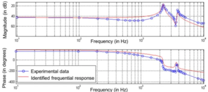
A low-amplitude sine voltage input u of increasing frequency is applied to the piezoactuator, where the vibrational dynamics are recorded experimentally. The tip deflection is also recorded during this experiment using the laser sensor. Bode diagram and the corresponding transfer functions were directly identified in frequency domain using a spectrum analyzer device (HP3562A). As expected by our pseudo-optimal design, the first two resonant modes are dominant among the higher frequencies residual modes(Fig. 7). The first point of interest of the criterion J2,3for the design is then validated. A reduced model of Gco(s), considering only these two dominant modes, can therefore be
identified confidently. We consider a truncated second-order modal transfer expansion of Gco(s) of the form:
2 ∑ i=1 kci 1+2ξi ωnis+ 1 ω2 ni s2 = Nco(s) D(s) (11)
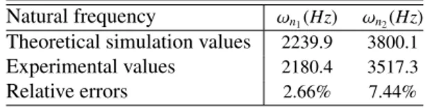
Damping ratiosξ1 = 2.0% and ξ2 = 2.5% are estimated from the frequency response using the measured quality factor at−3 dB: Q−3dBi ≈21ξ
i. Natural pulsationsωn1andωn2, calculated from the measured resonance frequencies are
reported inTable 1.
Table 1: Natural pulsations of Gco(s) transfer function.
Natural frequency ωn1(Hz) ωn2(Hz)
Theoretical simulation values 2239.9 3800.1
Experimental values 2180.4 3517.3
Relative errors 2.66% 7.44%
Static gains kc1 and kc2 are estimated to give both the correct frequency value for the first antiresonance (which
occurs between the two resonances) and the right static gain of the whole system. This identification procedure gives the following transfer polynomials:
Nco(s)=2.311 × 10⁻⁹s2+ 2.22 × 10⁻⁶s+ 0.08
D(s)=8.837 × 10⁻¹⁸s4+ 1.553 × 10⁻¹⁴s3+
6.802 × 10⁻⁹s2+ 4.934 × 10⁻⁶s+ 1.
(12)
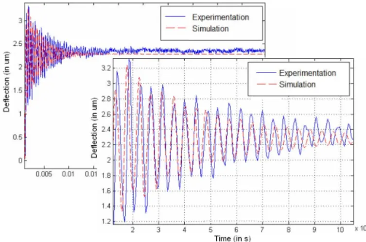
The identified response model is compared with experimental responses in frequency (Fig. 7) and time (Fig. 8) do-mains.
4.3. Characterization of the electric charge transfer operator 4.3.1. Experimental setup for electric charge measurement
To estimate the electric charges on the sensing electrodes pattern, the measurement electronic device is based on an operational amplifier in a current integrator operating mode (Fig. 9). This electronic setup uses a resistor Rcr in
Figure 7: Experimental Bode diagram of theδutransfer function (δ in µm and u in Volt) and corresponding identified transfer function.
Figure 8: Experimental transient response for theδutransfer operator (δ in µm and u in Volt) and corresponding identified response.
saturation effects at low frequencies, and to ensure an appropriate working of the electric charges integration. The measured output voltage Vs(s) = L(vs(t)) is related to the electric charges Q(s) = L(q(t)) in frequency domain as
follows: Vs(s)= L(vs(t))= − 1 C s+s1 RC Q (s) . (13)
Figure 9: Electronic charge-voltage converter used in the measurement of the electric charges q(t).
The operational amplifier is a micropower precision amplifier (National Semiconductor Corporation LF412ACN), which is characterized by a very low voltage drift with respect to the temperature (max. ±0.4 µ V/◦ C) and a low
offset voltage (max. ±150 µV). Its qualities in terms of stability and accuracy as well as its high bandwidth (130 kHz) makes it suitable for measuring nano Coulomb electric charges. The C feedback capacity is chosen equal to 2.2nF, a value close to the experimental capacity of the proprioceptive sensing area of the structure. The value of the resistor
Rcr= 10 MΩ must be large enough so as not to disrupt the integration function of the circuit. Along with this request,
it cannot be too large so as to avoid the discharge current to pass through it. The choice also depends on the cut-off frequency of the system, which should stay low to avoid the filtering of low frequency components.
4.3.2. Characterization of the electric charge transfer operator
The experimental procedure used for the identification of the dynamic behavior of the piezoelectric sensing area is similar to the previous one. A voltage is applied to the actuation area of the structure, while the output of the electronic charge measurement device is recorded. To avoid nonlinear phenomena, the same experimental cautions are taken during this experiment. The modal observability of the first two dominant modes is significant in the charge transfer function Q (s)/U (s) (Fig. 10). The roll-off at higher frequencies is sufficient to consider a simple fourth-order model as a reduced model for Gob(s).
Figure 10: Experimental Bode diagram of thequtransfer function (q in C and u in Volt) and corresponding identified transfer function.
4.3.3. Interests of the Jk,thvcriteria for vibrational dynamics identification
Insights both on frequency and spatial aspects into the pseudo-optimal structure can be given.
• In the frequency domain, if the optimization criterion Jk,thvis satisfied, then the dominant resonance peaks are
clearly visible and occur at the same frequency for both deflection transfer function (i.e. modal controllability authority) and charge transfer function (i.e. modal observability authority). This shows that including observ-ability based criterion from the first designing steps results in very effective design where a correspondance between the transfer functions is observed as seen in (Fig. 10). The experimental frequency response functions respects also the specific pattern imposed by our criterion in (Fig. 2). The vibrational dynamics polynomial
D(s) for the electric charge transfer function can be chosen equal to that corresponding to the actuation transfer function(11): 2 ∑ i=1 koi 1+ 2ξi ωnis+ 1 ω2 ni s2 = Nob(s) D(s) (14)
The computation of the static gains ko1and ko2are based on the identification of the zero (antiresonance) of the
experimental charge transfer function and static gain, to give :
Nob(s)= −1.407 × 10⁻¹¹s2− 1.506 × 10⁻⁸s− 0.007 (15)
The identified response model of the charge frequency response function matches the experimental frequency (Fig. 11) and time (Fig. 12) responses well.
• Regarding modal spatial shapes associated with ωn1 andωn2, significant modal strain of the actuation area
of the structure implies an important modal displacement of the output (i.e. high peaks amplitudes in the δu frequency response function) on one hand, and an important strain of the sensing piezoelectric beams (high
Figure 11: Correspondence of the dominant modesωn1andωn2in both deflection and charge transfer functions.
Figure 12: Experimental transient response for theVs
u transfer function (Vsin V and u in Volt) and corresponding identified response along with
the electronic instrumentation.
resonance peaks in the electric charge qu frequency response function) on the other hand (Fig. 13). Thus, such modal configuration explains why dominant resonant modes for deflection are well observed by electric charge measurement within the structure.
4.4. Linear modal state-space representation
Good observability of the dominant modes obtained through the criterion Jk,thv leads to vibrational dynamics
D(s) that are identical for both charge and deflection transfer functions in the frequency range of interest. These structural properties are of major importance to reconstruct the output displacement. From the identified frequency responses, the vibrational behavior of the whole structure can be reduced to their two dominant flexible modes, each one considered as a second-order transfer function. We recover the modal displacement in the Laplace domain as follows : zi= 1 s2 ω2 ni + 2ξis ωni + 1 , i= 1, 2 (16)
where the index i represents the i-th flexible mode. According to(3), the state vector x=( ˙z1 ωn1z1 ˙z2 ωn2z2
)t
is chosen. It leads to the following state space representation of the system for both the deflection and electric charge responses: ˙x= Ax + Bu yco= δ = Ccox yob= q = Cobx (17)
Figure 13:Mode shape plots of the pseudo-optimal structure associated withωn1on the left andωn2on the right. (Actuation and sensing parts
within the structure are reported in Fig. 3.)
with A= −2ξ1ωn1 −ωn1 ωn1 0 0 0 0 0 0 0 0 0 −2ξ2ωn2 −ωn2 ωn2 0 B=( ω2n1 0 ω2 n2 0 )t Cco= ( 0 kc1 ωn1 0 kc2 ωn2 ) Cob= ( 0 ko1 ωn1 0 ko2 ωn2 ) (18)
5. Control of the tip deflection
In previous section, the measurement of the tip deflection was performed using exteroceptive displacement sensor (laser sensor). A reduced electromechanical model of the tip deflectionδ as a function of the input control voltage
u was experimentally identified. As these works consider only linear effects of piezoelectricity, the corresponding
dynamical models have to be completed to consider nonlinear phenomena in a control-oriented perspective. The hys-teresis phenomenon in deflection will be identified and then compensated in this section. A cascaded High Authority Control (HAC)/ Low Authority Control (LAC) controller with damping feature will also be proposed and synthesized. Finally, this full control scheme will be implemented to ensure the performances required in micromanipulation tasks. In the following subsection, we take advantage of the proposed observability-based criteria Jk,thvto complete the control scheme with an observer. The relationship between the total electric charge q and the control voltage u is investigated. Finally, the estimated tip deflection ˆδ can be reconstructed efficiently through a modal state observer. This one exploits the proprioceptive sensing property of our pseudo-optimally-design device.
5.1. Control using exteroceptive laser sensor measurement 5.1.1. Nonlinear phenomena analysis
The deflection is non-linearly linked to applied voltage u through the hysteresis effect and the creep phenomena in a decoupled way. Hysteretical behavior depends on the past and present values of u but also on its frequency[21].
1. The creep phenomenon is the drift of the deflection observed after the transient part, when a step voltage is applied to the piezoelectric actuator. It can be considered as an additional behavior occurring when the steady-state is reached, so that it is often modeled as a simple delayed transfer operator[21]. Experimental results
show that the transient part of the piezoelectric microactuator is shorter than 300 ms whereas the creep settling time is longer than 180 s. As a consequence, the creep will be considered as a disturbance that must be rejected by the controller[22].
2. A± 80 V sine voltage input is applied to the system, and the free displacement output δ at the tip of the device is recorded.Experimental results of theFig. 14show the phase shift and the shape variation due to the mechanical linear vibrational dynamics Gco(s)[23]. The experimental static linear deflection is closed to the value predicted
by this method (static gain ks= Nco(s= 0) = 0.08µm/V).
Figure 14: Measured deflection hysteresis of the piezoelectric actuator for various frequency voltage inputs.
According to[24], we propose to model hysteresis phenomena with a static hysteresis operator Hs(u) of a
con-stant shape in series with a linear dynamical operator with an unitary static gain (Fig. 15). Indeed, it was already shown by authors in[25]that the linear vibrational characteristics of the transient response is independent of the amplitude of the voltage. Thus, in the following, the transient part will be assumed to be the normalized Gco
transfer function (i.e. with an unitary static gain).
Figure 15: Dynamic hysteresis equivalence.
5.1.2. Hysteresis compensation using the Prandtl-Ishlinskii (PI) static hysteresis model
To perform the linearization, the inverse static model H−1s (u) is put in cascade with the system (Fig. 16). The
Prandtl-Ishlinskii (PI) model has been chosen due to its simplicity and accuracy[26]. This one is based on the superposition of several elementary backlash operators characterized by their threshold r and weighting coefficient h. Let Hri[u, δi0(t)] be the i-th backlash operator characterized by its threshold riand initial stateδi0. The static deflection δsis given by the following equation according to PI operator:
δs= Γ(u) = [h]t. [ HrH [ u, δH0 ] (t)], (19) where HrH [ u, δH0 ] (t)=[Hr0 [ u, δ00 ] (t). . . Hrn [ u, δn0 ]
(t)]tis the (n+ 1) vector of backlash operators and [h] = [h0...hn]t
Figure 16: Scheme of the hysteresis compensation.
The computation of the inverse PI model is another static PI hysteresis, considering that the deflection is the input and the voltage is the output. Based on the same principle as the direct PI model, the new thresholds r′iand weighting elements h′iare given as follows :
r′i = i ∑ j=0 hj ( ri− rj ) , i = 0, . . . , n (20) and h′0= −1 h0 (21) h′i= ( −hi h0+ i ∑ j=1 hj ) ( h0+ i∑−1 j=1 hj ) , i = 1, . . . , n. (22)
The PI model has been identified with 18 backlash operators, considering a 80V sine voltage applied to the piezoelectric device. The output tip displacementδ is directly measured from the laser sensor. A 0.5 Hz low frequency, far below the resonant frequencies, has been selected for experiments to avoid the dynamic effects on the hysteresis shape. Following the identification procedure (Fig. 17), the inverse model is implemented in the controller and shows a good effectiveness in the compensation of the hysteresis (Fig. 18).
Figure 17: Identification of the static experimental hysteresis.
5.1.3. A HAC/LAC damping strategy for in-plane motion control
This approach combines two different loops as shown onFig. 19: the active damping regulator Hl(LAC) reduces
the settling time of transient response, while a (HAC) compensator HLachieves integral action at low frequency and
significant modifications to the open-loop system poles. The HAC controller deals with the trade-off between the conflicting requirements of performances-robustness-stability. The outer loop of the compensator is designed on the damped structure.
If we consider that the two first vibrational modes are dominant, i.e. reduced identified model can efficiently approximate the full model, a very simple LAC controller can be designed. This one provides good intrinsic stability properties for such king of systems. Considering the trajectory of the closed-loop system poles in the complex plane, the use of a pure gain Hl(s)= g = 7 as a feedback Hlcontroller is chosen to decrease the influence of the first resonant
Figure 18: Experimental results of hysteresis linearization in quasi-static (before PI compensation - maximum hysteresis of 31% and after PI compensation - maximum hysteresis of 3%) and low-frequency sine input trajectory reference trackingδr(t).
Figure 19: Scheme control of the cascaded HAC/LAC loops.
mode of the compensated system (Fig. 20). This gain value is chosen based on simulation analysis through the root locus of the system.
Figure 20: Bode diagrams in magnitude of the open-loop transferδ(s)/u(s) and pre-compensated closed-loop transfer with Hl(s).
To increase the gain at low frequency, the HAC compensator includes a simple integral action, to eliminate the static error and to reject disturbance. At high-frequency, it provides sensor noise rejection and stability robustness. A simple multiplicative term has been added to the integrator HL(s)= kHL/s to increase the bandwidth of the pre-compensated loop transfer up to 220 rad/s.
Lco(s)=
HL(s) Gco(s)
1+ Hl(s) Gco(s)
(23) The resulting regulator provides interesting gain and phase margins, Mg= 23 dB and Mφ= 82 deg at ωP= 256 rad/s
respectively. Steps were experimentally applied to the device to validate the performances of the whole HAC/LAC controller along with the P.I. compensator, providing a settling time of t5% = 12.5 ms (Fig. 21). Let us note that the bandwidth that is reached by our low-order control scheme is compatible with micromanipulation tasks requirements and similar to bandwidth of other control schemes[27] [21].
Figure 21: Experimental step response to a 2.8µm-amplitude reference for the HAC/LAC compensated system.
5.2. Control using proprioceptive electric charge observation
In this section, we present the design of a position observer that take into account the benefits obtained by the observability-based criteria Jk,thvduring the design of the system. This observer permits to efficiently reconstruct the tip deflection estimate ˆδ through a modal state observer based on the proprioceptive sensor (Fig. 5). The algorithm uses a modal observer to reconstruct the linear dynamics of the tip deflection. This one is completed with additional features to take into account nonlinearities that may occur in the piezoelectric induction of electric charges.
5.2.1. Observer poles placement
To observe the linear dynamics of Gob(s), a Luenberger state observer, is implemented as:
˙ˆxˆyob= Aˆx + Bu + K= ˆq = Cobˆx ob(yob− ˆyob) (24) The observer gains of the (4× 1) vector Kobare chosen such that the prediction error e= x − ˆx vanishes according to ˙e= (A − KobCob) e.
Robustness analysis of the whole observer-based control scheme is performed. The HAC/LAC control action is expressed in the Laplace domain as follows:
u(s)= HL(s) (δr− δ) − Hl(s)δ (25)
According to previous section, Hl(s)= g and HL(s)= kHL/s and thus: u(s)=kHL s δr− ( g+kHL s ) Ccoˆx (26)
The open-loop system including modal state observer and controller is then deduced from(24)and(26)as:
Lob(s)= Gob(s) K (s) (27) where u(s)= K (s) yob(s)= − ( g+kHL s ) CcoKob ( sI − A + KobCob+ ( g+kHL s ) BCco )−1 yob(s) (28)
The four gains of the Kobvector are computed following a root-clustering procedure, with an observation dynamics four times faster than the control dynamics. In addition, observation poles are chosen real to avoid oscillations. The resulting regulator provides interesting gain and phase margins, Mg= 26 dB and Mφ= 77 deg respectively.
5.2.2. Non-linearities modeling and compensation
Electric charges modeling is a linear function of the mechanical strain in piezoelectric materials[28]. Nevertheless and as it was previously shown, there is an hysteretical behavior between applied voltage and the actuated beams strain. But this non-linearity affects also sensing parts strain, because actuation deforms the whole structure, and therefore affects the strain of the sensing parts. The hysteresis non-linearity between applied voltages and controlled output
yco = δ was efficiently corrected with the help of PI operator H−1s . Nevertheless, as measured output yob = q are not
controlled output yco = δ, this compensation is not able to linearize the transfer between the observed output yob and
the input applied voltage u (Fig. 22).
Figure 22: Measured charge hysteresis of the sensitive area of the system for various frequency voltage inputs.
Figure 23: Complete observation/control scheme based on proprioceptive measurement.
The non-linearity compensation of q/u transfer operator have to be done in a second step after the reconstruction of the output yco= δ as ˆδ. A curve fitting technique is used to linearize the steady-state hysteresis phenomenon that affect
the charge induction. This compensation algorithm permits a fast and efficient corrective action (Fig. 23). The modal state observer estimates the linear contribution of the ˆδ deflection through the Kobmatrix. It captures the transient part
of the deflection. The observer output ˆδ is then corrected by the curve fitting technique into a new deflection ˆδcwhich is
send to the controller. A characterization process that maps ˆδ into ˆδcwas achieved off-line, considering all the various
signals combination of variable amplitudes, with a 0.2µm resolution compatible with the manipulation requirements. The values of the steady-state deflection ˆδc(measured with exteroceptive laser sensor) and the estimated deflection ˆδ
(estimated with the Luenberger observer) are collected and compared for each set point stage, and classified in rising and falling edges. Each ratio ri j =
δci j
ˆ
δi j is calculated and stored into a table for interpolation. It depends on the index i of the considered stage set point, and the index j on whether the current reference is rising or falling (equal to 1 or
2). Then, in operating mode, the corrected ˆδcdeflection is computed on-line according to ˆδci j = ri jδˆi j. Experimental results of the full observation process, i.e. linear state observer and compensation, shows the effectiveness of the proposed method to reconstruct the tip deflection: the vibrational dynamic is well captured and the static nonlinear effect is well compensated (as can be shown onFig. 24).
Figure 24: Step responses of the deflection for different operating voltages.
5.2.3. Experimental results of the deflection control using proprioceptive observation
The whole control system depicted on theFig. 23was tested with a step position reference signal. The response of the experimental system does not exhibit any overshoots, and the response time is approximately t5% = 13 ms. Furthermore, the use of an observer tends to filter the measurement noise phenomenon which appears when the exteroceptive laser sensor is used(Fig. 25). Using proprioceptive information seems therefore very attractive for the end-effector control. To emphasize the effectiveness of this observer/controller architecture, reference steps of various amplitudes were experimentally applied to the device. For each of theses reference signals, the tracking performances are validated without overshoot and the deflection hysteresis is also well compensated(Fig. 25).
Figure 25: Experimental step response (on the left) and tracking response (on the right) for the HAC/LAC system including observer and non-linear compensation (Fig. 23).
6. Discussions and conclusions
In the micromechatronic field, designers of integrated systems are faced with complex multi-objective design problems. The strategy proposed in this paper led to the design of a compliant microactuator that optimally inte-grates actuating and sensing areas in monolithic structures. We took advantage of versatile criteria to synthesize high performance microrobotic flexible mechanism designs. In addition to classical mechanical criteria currently encoun-tered in topology optimization (i.e. force and displacement maximization), it is of great interest to consider efficient observability-based criteria simultaneously. These criteria can fully and optimally integrate the actuation and sensor capabilities into the structure, as regards to the performances achievable by the controller.
Considering dynamic effects from the first design steps is of a particular interest when dealing with flexible struc-tures as it was demonstrated for the design of a piezoelectric microgripper. Indeed, taking advantage of our frequency-based criterion, the dominant vibrational modes which govern the tip deflection of the device are now fully observable from the integrated sensing area of the device. From a topological point of view, considering observability-based criteria to shape the open-loop frequency response of both the controlled deflection and observed electric charges gives an efficient and well designed full microrobotic device. In particular, this effectiveness allows an efficient and confident observer-based reconstruction of the tip-deflection.
Regarding the reduced modal content of the deflection transfer function, a very simple HAC/LAC control ap-proach can ensure good performance in tracking. Even if HAC/LAC methods are not new in control literature, this paper is one of the few to show its power for flexible microactuators control. In comparison with classic robust control approaches, this one is competitive in terms of robustness and performances. Based on the pseudo-optimal proprio-ceptive sensing capabilities of our device, a simple modal observation process reconstructs efficiently the dynamics of the deflection of the microactuator.
More complex charge integration techniques for low frequency signals could be considered in future works. In particular, electronic circuitry based on analog-to-digital converter could be used to integrate and to numerically cap-ture peak values of electric charge signal that is generated by the sensor when subjected to a static load. Measurement accuracy could also be improved by utilizing feedback techniques to compensate for the signal loss due to charge leakage.
The problem of high-pass filter created by capacitive source impedance of piezoelectric sensors can also be over-come by using a low-frequency bypass technique[29]. In this approach, the low-frequency component of the mea-sured signal is replaced by an estimate based on the system input and an open-loop model. The actual output of the piezoelectric sensor is complemented with an estimate at frequencies below the crossover frequency and do not add dynamics to the control loop.
The optimal integration of piezoelectric actuation and sensor capabilities within the structure from both the me-chanical and control-/observation- points of view illustrates the concept of smart adaptronic system. Natural perspec-tive of these works are the possible integration of this control structure into system-on-chip.
References
[1] J. M. Breguet, al., Monolithic piezoceramic flexible structure for micromanipulation, in: 9th International Precision Engineering Seminar and 4th International Conference on Ultraprecision in Manufacturing Engineering (IPES-UME’1997), Braunschweig, Germany, 1997, pp. 397–400.
[2] D. Campolo, R. Sahai, R. S. Fearing, Development of piezoelectric bending actuators with embedded piezoelectric sensors for micromechan-ical flapping mechanisms, in: IEEE Int. Conf. on Robotics and Automation (ICRA 2003), Taipei, Taiwan, 2003, pp. 3339–3346.
[3] P. J. C. Branco, J. A. Dente, On the electromechanics of a piezoelectric transducer using a bimorph cantilever undergoing asymmetric sensing and actuation, Smart Materials and Structures 13 (2004) 631–642.
[4] M. Grossard, N. Chaillet, S. Regnier, Flexible Robotics: Applications to Multiscale Manipulations, Wiley, 2013.
[5] H. Janocha, Adaptronics and Smart Structures - Basics, Materials, Design and Applications, 2nd ed., Springer-Verlag, 2007.
[6] J. H. Han, I. Lee, Optimal placement of piezoelectric sensors and actuators for vibration control of composite plate using genetic algorithms, Smart Materials and Structures 8 (1999) 257–267.
[7] M. Moallem, M. R. Kermani, R. V. Patel, M. Ostojic, Control of a positioning system with structural flexibility using piezoelectric transducers, in: 42nd IEEE Conference on Decision and Control (CDC’2003), Vol. 5, 2003, pp. 4505–4510.
[8] S. Leleu, H. Abou-Kandil, Y. Bonnassieux, Piezoelectric actuators and sensors location for active control of flexible structures, IEEE Trans. on Instrumentation and Measurement 50(6) (2001) 1577–1582.
[9] E. Silva, S. Nishiwaki, N. Kikuchi, Design of piezocomposite materials and piezoelectric transducers using topology optimization - part ii, Computational Methods in Engineering 6 (1999) 191–222.
[10] S. Wang, K. Tai, S. T. Quek, Topology optimization of piezoelectric sensors/actuators for torsional vibration control of composite plates, Smart Materials and Structures 15 (2006) 253–269.
[11] M. Abdalla, al., Design of a piezoelectric actuator and compliant mechanism combination for maximum energy efficiency, Smart Material and Structures 14 (2005) 1421–1430.
[12] M. Maddisetty, M. Frecker, Dynamic topology optimization of compliant mechanisms and piezoceramic actuators, ASME Journal of Me-chanical Design 126 (2002) 975–983.
[13] B. Zheng, C.-J. Chang, H. G. Gea, Design of piezoelectric actuator with in-plane motion using topology optimization, in: ASME International Design Engineering Technical Conferences and Computers and Information in Engineering Conference (IDETC/CIE’2007), Las Vegas, Nevada, USA, 2007.
[14] B. Zheng, C. Lu, H. Z. Huang, Topology optimization of piezoelectric force sensor, in: International Conference on Apperceiving Computing and Intelligence Analysis (ICACIA’2008), 2008, pp. 132–136.
[15] H. Du, al., Topological optimization of mechanical amplifiers for piezoelectric actuators under dynamic motion, Smart Material and Structures 9 (2000) 788–800.
[16] R. El Khoury Moussa, M. Grossard, N. Chaillet, M. Boukallel, A. Hubert, Optimal design and control simulation of a monolithic piezoelectric microactuator with integrated sensor, in: IEEE/ASME International Conference on Advanced Intelligent Mechatronics (AIM’2010), 2010, pp. 420–425.
[17] E. Jonckheere, Principal components analysis of flexible systems - open-loop case, IEEE Trans. on Automatic Control 29 (1984) 1095–1097. [18] R. El Khoury Moussa, M. Grossard, M. Boukallel, A. Hubert, N. Chaillet, Optimal observability-based modelling, design and characterization
of piezoelectric microactuators, Smart Materials and Structures 22 (7) (2013) 075036.
[19] B. J. G. Vautier, S. O. R. Moheimani, Charge-driven piezoelectric actuators for structural vibration control: Issues and implementation, Smart Materials and Structures 14 (4) (2005) 575–586.
[20] W. Gawronski, K. B. Lim, Balanced control of Flexible structures, Springer-Verlag, 1996.
[21] M. Rakotondrabe, Y. Haddab, P. Lutz, Quadrilateral modelling and robust control of a non-linear piezoelectric cantilever, IEEE Transactions on Control Systems Technology 17(3) (2009) 528–539.
[22] M. Rakotondrabe, Y. Haddab, P. Lutz, Non-linear modeling and estimation of force in a piezoelectric cantilever, in: IEEE/ASME Interna-tionale Conference on Advanced Intelligent Mechatronics (AIM’2007), 2007.
[23] S. Devasia, E. Eleftheriou, S. O. Moheimani, A survey of control issues in nanopositioning, IEEE Transactions on Control Systems Technol-ogy 15 (2007) 802–823.
[24] D. Croft, G. Shed, S. Desavia, Creep, hysteresis and vibration compensation for piezoactuators: atomic force microscopy applications, Journal of Dynamic Systems, Measurements and Control 123(1) (2001) 35–43.
[25] M. Grossard, M. Boukallel, N. Chaillet, C. Rotinat-Libersa, Modeling and robust control strategy for a control-optimized piezoelectric microgripper, IEEE/ASME Transactions on Mechatronics 16 (2010) 674–683.
[26] M. Rakotondrabe, C. Clevy, P. Lutz, Complete open loop control of hysteretic, creeped, and oscillating piezoelectric cantilevers, IEEE Transactions on Automation Science and Engineering 7(3) (2009) 440–450.
[27] S. Khadraoui, M. Rakotondrabe, P. Lutz, Interval modeling and robust control of piezoelectric microactuators, Control Systems Technology, IEEE Transactions on 20 (2) (2012) 486–494.
[28] A. Preumont, Vibration control of active structures: an introduction, 2nde Ed., Kluwer academic publishers, 2002.
[29] Y. K. Yong, A. Fleming, S. Moheimani, A novel piezoelectric strain sensor for simultaneous damping and tracking control of a high-speed nanopositioner, Mechatronics, IEEE/ASME Transactions on 18 (3) (2013) 1113–1121.