HAL Id: hal-03177944
https://hal.archives-ouvertes.fr/hal-03177944
Submitted on 24 Mar 2021
HAL is a multi-disciplinary open access
archive for the deposit and dissemination of
sci-entific research documents, whether they are
pub-lished or not. The documents may come from
teaching and research institutions in France or
abroad, or from public or private research centers.
L’archive ouverte pluridisciplinaire HAL, est
destinée au dépôt et à la diffusion de documents
scientifiques de niveau recherche, publiés ou non,
émanant des établissements d’enseignement et de
recherche français ou étrangers, des laboratoires
publics ou privés.
Adrien Debord, Eric Lucet, Faïz Ben Amar
To cite this version:
Adrien Debord, Eric Lucet, Faïz Ben Amar. Mobile robot behavior adaptation in navigation space
shared with human. MCG 2016 –5th International Conference on Machine Control & Guidance, 2016,
Clermont-Ferrand, France. �hal-03177944�
MCG 2016 – 5th International Conference on Machine Control & Guidance
“Facing complex outdoor challenges by inter-disciplinary research”
Vichy, France, October 5-6th, 2016
Mobile Robot Behavior Adaptation in Navigation Space
Shared with Human
Adrien Debord
1, Eric Lucet
1, Faïz Ben Amar
21CEA, LIST, Interactive Robotics Laboratory, Gif-sur-Yvette, F-91191, France
2Université Pierre et Marie Curie Institut des Systèmes Intelligents et de Robotique, Paris, France
Keywords: Mobile robot, man-robot interaction, path planning.
Abstract: The paper presents an approach to the navigation of autonomous mobile platforms among people in a warehouse environment. When navigating in the presence of human, obstacle avoidance is not sufficient to assure a harmonious cohabitation. Indeed the robot should consider the personal space of people and its expected behaviour. So, to take this considerations into account, a two levels control algorithm is proposed. Depending on the situation encountered, each level is producing a different behaviour to be adopted by the robot. Moreover, a dynamic definition of the proxemics area of the person enables the robot to deal with cluttered areas while keeping its distances when needed. The approach has been simulated and tested against state of the art algorithm. Then, it has been fully implemented and tested.
1
INTRODUCTION
With the growth of the collaborative robotics, robots are facing a new challenge: the cohabitation with humans. The case of static manipulators has been widely covered. and implemented in factories. However, the case of mobile robots is still challenging. Indeed, in warehouse context we can guarantee the safety of people around mobile robots. But safety is not enough for human-robot cohabitation (Shi, 2008). Even if the robot never collides with humans, it can still be perceived as threatening or unsure which will cause stress and discomfort. Hence studies have been carried out to know what rules robots should follow to prevent inducing such feelings to the human encountered. In that aim, (Hall, 1966) has defined a list of concentric areas around the person defining where people prefer others to be, depending on the kind of interaction they have. These area are called proxemic areas. They are usually taken into account when reasoning about human aware navigation (Pacchierotti, 2006), (Truong, 2014), (Scandolo, 2011).
Also, there is the need to know what the robot should do in which situation. In particular, there have been several studies about the crossing behavior. During a front crossing or overtaking, the robot should maneuver around the person. However
when side crossing, the robot should stop instead of deviating from its trajectory (Lichtenthaeler, 2013). People tend to project a model of mind onto the robot. It is how we work, we take the representation of our own mind and distort it to fit in what we think of the robot (Lu, 2014). Hence, the robot should also give clear informations about its intentions even if it doesn't really have some (Kruse, 2012). Plus it should have a smooth trajectory for the same reasons. A robot that has an erratic trajectory will be perceived as unstable and hence not trustful at all.
In this paper, the environment is defined as a warehouse. The mission of the robot is to navigate successfully in this environment by considering the presence of humans evolving in the same area. This area is modeled by an array of hallways and crossings. The main objective is to find a compromise between an optimal path, with regard to the travel time, and a path minimizing the stress and discomfort of people. Several strategies have already been explored: in (Pacchierotti, 2006) and (Pandey, 2009), way-points are added to the robot's path to make sure the robot is avoiding the person correctly. In (Suzuki, 2009) the path planner is using a dynamic map considering people as moving obstacles. Also a great effort is spent to get the planner to produce smooth paths. This work is performed by considering the length of the path covered by the wheels instead of the distance
P a g e
|
2
covered by the center of the robot. Hence, the planner is limiting pure rotations, which is making the path smoother. In (Hoeller, 2007), a technique involving potential fields is used to match the proxemic areas. However, most of the work on human aware navigation has been done by building a personal area around the person which is used as a cost function for the robot's planner. To prevent the robot from going where the person will be in a few moments, its trajectory is distorted in the direction of the person speed (Lam, 2011), (Truong, 2014). There is also more complex type of area which stack multiple comportment rules like in (Scandolo, 2011) where not only the speed is taken into account but also the back of the person and its personal space plus the intimate space which is totally forbidden. Although this method may be more general than the others by dealing better with multiple persons and being easier to interface with other rules, it doesn't handle all the cases that a robot may be facing in the warehouse context. Indeed the crossing and following behaviors are not properly handled.
In his thesis (Kruse, 2012), T. Kruse is proposing a solution to handle the the crossing case by making the robot choose between two methods to avoid a person. One is to make the robot change its path and the other one is to make it slow down and stop if necessary. This paper will go further in this direction.
In the second section, the control architecture principle is described. Implementation of the modified algorithm is presented in the third section. Then, Results are analysed in the fourth section. Finally, in last section we present our conclusions and perspectives.
2
CONTROL ARCHITECTURE
When a mobile robot is close to a person, two distinct possible behaviors are identified:
The detour: the robot should modify its path to avoid the person;
Slowing down: the robot slows down until stop if needed.
In most cases, to minimize the navigation time, the robot should do a detour to avoid collision with the person. However, when crossing from the side and when the robot is behind a person that is moving faster, the robot may not adapt its path. It should instead slow down and stop if needed.
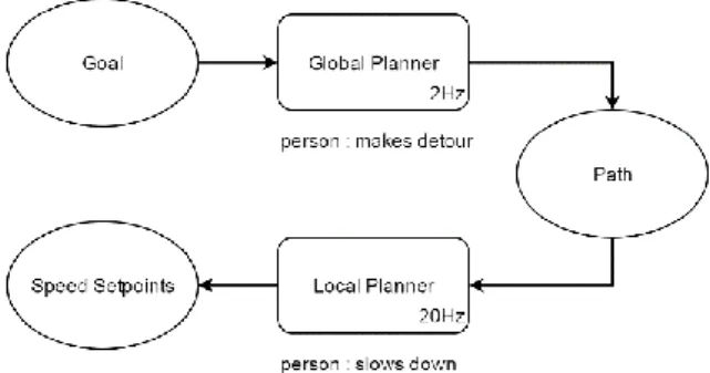
For a choice determination between these two behaviors, the control algorithm is split in two levels (architecture from (Kruse, 2012), see Figure 1).
An A* algorithm upgraded with diagonals consideration is used by the global planner. It is reacting to the presence of people by modifying the path of the robot.
Then, a local planner is sending the speed setpoints to the robot's controller. For that, a set of trajectories is generated: first the command space is sampled, then the algorithm is building the robot theoretical trajectories computed with these setpoints, and finally each trajectory is evaluated to choose the one with least cost allowing obstacles clearance. The cost function used for this choice is described in the following. The local planner is updated each 20Hz and its main role is to avoid the obstacles while following the path. It is handling people avoidance by slowing down the robot rather than by modifying the path.
For the robot behavior determination, it is hidden or not to the global planner. Hence, by hiding it, the path is going straight through the person. Consequently, the local planner is modulating the robot speed. Otherwise, if the person is not hidden, the trajectory generated by the global planner is avoiding the person. Thus, the trajectories of the robot and the person will never meet.
Figure 1: Control Architecture. The global planner receives a goal and produces a path at a 2Hz frequency. This path is sent to the local planner which computes the speed setpoints to be sent to the controller at a 20Hz frequency.
3
IMPLEMENTATION
In this section, the implementation of behavior algorithms is described in details. First, the structure of the cost function used to build the path and evaluate the trajectories is introduced. Then, an extensive description of how the costs for path finding are computed is given. Finally, the implementation of the local planner is described.
MCG 2016 – 5th International Conference on Machine Control & Guidance
“Facing complex outdoor challenges by inter-disciplinary research” Vichy, France, October 5-6th, 2016
3.1
Cost Map
First, for both the global and local planners, a cost map is used to describe the topology of the environment. It is a grid representing the map of the area, each cell being associated with a cost for the robot to travel through. A maximum cost is defined, corresponding to an impassable obstacle.
This map is built from a known map of the area plus the data of the robot laser sensor. Then, obstacles are inflated with a decreasing cost to make the robot prefer not to be too close form walls. A cell cost is written c and the total cost used by the planners is C.
For people handling, first their footprint are hidden on the laser scans feeding the global planner cost map. Then, a gaussian area H extended in the direction of speed, is built around people in both local and global cost maps. This repulsive area around the person is making the robot prefer keeping its distances with the person. In particular, the area extension in the speed direction is making the robot anticipating the movement of the person. Then, to switch between the two behaviors, this area is modulated by an incompatibility function ɸ, that is hiding or not the person to the global planner. Hence, the cost C is :
𝐶 = max(𝑐, 𝜙 × Η)
(1)
3.2
Repulsive Area
The repulsive area around people is defined as follows: Η = s. 𝑐𝑚𝑎𝑥. {
𝑒
− 𝑥2+𝑦2 2(𝑠𝑑𝑖𝑠𝑡3 )2 𝑖𝑓 𝑥 ≤ 0𝑒
− ( 𝑥2 2(𝑠𝑑𝑖𝑠𝑡+𝑘.𝑣ℎ3 )2 + 𝑦2 2(𝑠𝑑𝑖𝑠𝑡3 )2 ) 𝑒𝑙𝑠𝑒(2)
The referential is centered on the person, its speed vector being along the 𝑥 axis. The cell coordinates for cost computing are (𝑥, 𝑦), the speed of the person is 𝑣ℎ. 𝑐𝑚𝑎𝑥 corresponds to the cost value of a static obstacle and 𝑠𝑑𝑖𝑠𝑡 is the desired social distance from the robot. The coefficient 𝑘 allows to augment the area for an anticipation of few seconds of the person movement. A global gain 𝑠 is added to increase the cost of the private area until a higher value than the one the static obstacles cost. The Η function maximum value being 𝑐𝑚𝑎𝑥− 1, with the gain 𝑠 the robot is not going to decide to pass through the person if it has another choice.
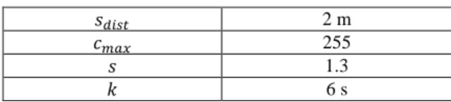
Parameters values are listed in Table II. 𝑠𝑑𝑖𝑠𝑡 is chosen as the middle of the social area (between two and three meters), 𝑐𝑚𝑎𝑥 is an arbitrary value set to 255. 𝑠 is calculated so that Η(𝑖𝑑𝑖𝑠𝑡) = 𝑐𝑚𝑎𝑥 where 𝑖𝑑𝑖𝑠𝑡 is the intimacy distance ≈ 0.5𝑚. 𝑘 value is defined from the consideration that 3m of anticipation are needed to avoid correctly a person walking at 0.5m/s.
Table 1: People Area Parameters
𝑠𝑑𝑖𝑠𝑡 2 m
𝑐𝑚𝑎𝑥 255
𝑠 1.3
𝑘 6 s
3.3
Incompatibility function ɸ
The purpose of this function is to hide the person from the robot for it to slow down instead of making a detour. It depends on the position and velocity of the robot along the path. Thus, this function has to be recalculated at each step of path planning. Furthermore, because the global planner only draws a list of successive positions, some assumptions have to be made to determine the orientation and velocity of the robot. The orientation is defined as detailed in (Kruse, 2012). When the planner is evaluating a new point, it corresponds to the orientation of the vector form the previous point to the one to be evaluated. The 𝑣⃗⃗⃗ speed norm is the 𝑟 maximum speed of the robot and its orientation is the one of the robot.
The function is defined as follows: if the person is static, the robot has to get around him, so he is not hidden. If the person and the robot are moving away and sufficiently far from each other, it is not needed to take the person into account, the robot and the person never meet. If the person and the robot are crossing sideways, the robot has to stop instead of getting around the person, so the person has to be hidden from the global planner. Finally, if none of these conditions are met, the person is coming from the front or is being caught up by the robot. Thus, he has to be avoided. This explanation of the function can be summarized as follows:
Φ = { 1 𝑖𝑓 ‖𝑣⃗⃗⃗⃗ ‖ ≤ 𝑣ℎ ℎ 𝑚𝑖𝑛 0 𝑖𝑓 𝑣⃗⃗⃗ ∙ 𝑅𝑃𝑟 ⃗⃗⃗⃗⃗ < 𝑣⃗⃗⃗⃗ ∙ 𝑅𝑃 ℎ ⃗⃗⃗⃗⃗⃗ 𝑎𝑛𝑑 ‖𝑅𝑃⃗⃗⃗⃗⃗ ‖ > 𝑖𝑑𝑖𝑠𝑡 0 1 𝑖𝑓 60 °< 𝛼 < 120° 𝑒𝑙𝑠𝑒
(3)
Where α is the angle between the robot and the person directions. 𝑣⃗⃗⃗⃗ is the speed of the person and ℎ
P a g e
|
4
𝑅𝑃
⃗⃗⃗⃗⃗ is the vector from the robot to the person. 𝑣ℎ 𝑚𝑖𝑛 is the lowest limit for the speed of the person before considering it immobile.
3.3
Local planner
As stated before, the local planner is considering trajectories the robot would have for each possible velocity. Cost functions and filters are used to evaluate those trajectories. First, all the trajectories inducing a collision with a static obstacle are removed. Then for moving objects, we implemented the method of (Seder, 2007). While iterating over the positions of the robot along the trajectory, the moving obstacles are moved according to the prediction of their movement. In particular, movement of persons is considered as linear with constant speed. Because the time horizon of the local planner is short (few seconds), this approximation is acceptable.
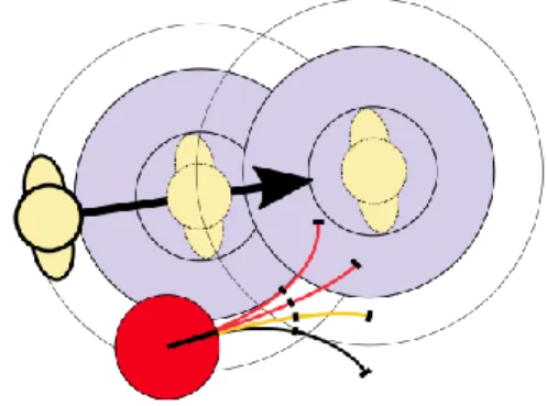
When the person is hidden from the global planner, the local planner has to take into account the proxemic area of the person. To achieve this goal, the collision area around the person is increased to match his personal area (1m radius). Hence the robot will avoid to come too close to the person during the slow down behavior, especially when crossing the person's path sideways. However, because this inflated area appears and disappears, the robot may remain stuck inside it. To prevent this, only the last point of the robot trajectory is evaluated. This way, a trajectory that makes the robot going out of the area or that passes briefly through becomes valid (Figure 2). At each step of the evaluation of each trajectory, the local planner extrapolates the position of the person. Three steps are represented in Figure 2. The two inner circles represent the person and robot radius, they define the collision area. The inflated area is in thin line. The two red trajectories have at least one point in the collision area so they are rejected. The yellow one doesn’t intersect with the collision area, so it is valid for collision avoidance. However its last point is in the inflated area making it invalid if the inflation is active. Finally, although the black trajectory has its first points in the inflated area, its last is out so it is still valid with inflation on.
Then, remaining trajectories are evaluated with four cost functions:
Distance to the objective: 𝑂𝑏𝑗 Distance to the path: 𝑃𝑎𝑡ℎ Crossing cost of the cell: 𝐶
Direction of the robot at the end of the trajectory: 𝐷𝑖𝑟
Figure 2: Inflated intimate area
The final score of the trajectory is a weighted sum of these functions (see Table 2 for parameters):
𝑆𝑐𝑜𝑟𝑒 = 𝑜𝑏𝑗𝑠× 𝑂𝑏𝑗 + 𝑝𝑎𝑡ℎ𝑠× 𝑃𝑎𝑡ℎ + 𝑐𝑒𝑙𝑙𝑠× 𝐶 + 𝑑𝑖𝑟𝑠× 𝐷𝑖𝑟
(4)
Table 2: Local Planner Parameters
𝑜𝑏𝑗𝑠 0.4 𝑝𝑎𝑡ℎ𝑠 1.7 𝑐𝑒𝑙𝑙𝑠 0.006 𝑑𝑖𝑟𝑠 0.3 time horizon 3 s max velocity 0.5 m/s
4
EXPERIMENTATIONS
Experimentations have been carried out on a unicycle Pioneer P3-DX from mobile robots (MobileRobots, 2016). It has two motor wheels on the sides and one idler wheel on the back. The speed is 0.5m/s and it has been equipped with a planar lidar and odometers.
The presented algorithm is compared to the initial one of Kruse. Every configuration of ɸ is tested: one scenario with a static person (Figure 3a) for each position of the robot around it, one scenario from behind, one scenario in face to face (Figure 3d) and one from side (Figure 3b). Then, the relative speed between the robot and the person has to be considered, which is relevant for the following scenarios (Figures 3e and 3c).
Modifications made to the ɸ function from (Kruse, 2012) had two purposes: one is to make the robot able to overtake the person when he is too slow and the second one is to make the stop distance of the local planner context dependent. Indeed, in Kruse algorithm, the distance at which the local planner has to stop is static. However when crossing sideways, it is desirable that the robot stopes at a great distance from the person but it also should be
MCG 2016 – 5th International Conference on Machine Control & Guidance
“Facing complex outdoor challenges by inter-disciplinary research” Vichy, France, October 5-6th, 2016
able to cross someone coming in front of it event in cluttered areas. So the stop distance should not be too big in that cases.
Figure 3: Scenarios: person in yellow and robot in red
4.1
Simulation
In this section, the performance of the proposed algorithm is compared to the Kruse one. The two trajectories produced by each algorithm are compared and curves of the distance between the robot and the person and of the robot speed are analyzed. The Safety Limit which is the size of the person intimate area (0.5m) plus the robot radius (0.3m) is represented in the distance graph. A “Personal Limit” of 1.3m representing the personal area of the person plus the radius of the robot is also drawn.
In following Figures, the trajectory from Kruse's algorithm is in red, the proposed solution has a blue one and the person is in green. A circle is drawn every three seconds and the arrow indicates the direction of movement. The environment of the robot is a crossing between two 3m large corridors.
The simulator used is the Gazebo 3D physics simulator. The robot is modeled as a rigid body with three cylindrical wheels with a vertical rotation for the idle one. The friction between the wheels and the floor is modeled with a regularized Coulomb law. People positions are recorded by the simulator to be directly fed to the algorithm.
4.1.1 Static crossing
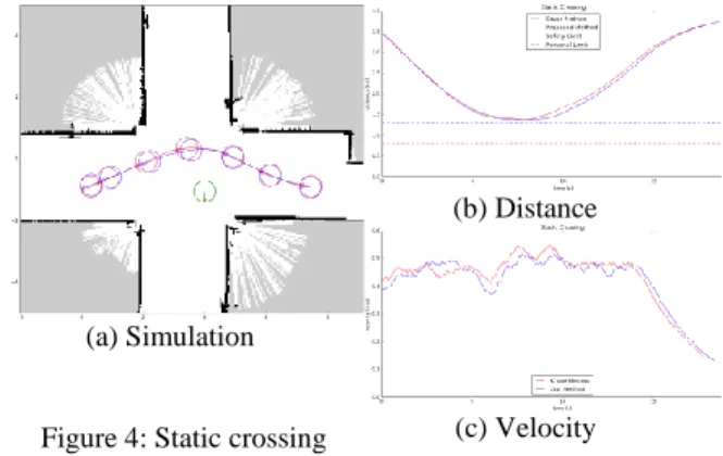
In this scenario (Figure 4), the robot starts in front of the person which does not move. It has to go to a point behind it. Trajectories are similar. The incompatibility function is set to one, showing the person to the global planner which produces a detour. Distance curves are very similar, the lowest measure being 1.37m which is satisfying considering the room available. Also, the two velocity records
are similar, decreasing at the end because the robot is about to reach its goal.
(a) Simulation
Figure 4: Static crossing
(b) Distance
(c) Velocity
4.1.2 Side crossing
The robot is crossing the person path perpendicularly (Figure 5). It should stop to let the person pass. With both algorithms, the person arrives sideways so he is hidden to the global planner, hence the path is not modified. The speed is modulated by the local planner. Trajectories are similar. The robot slows down with both algorithms. Distance curves indicate that with Kruse algorithm, the robot gets significantly closer: 0.89m instead of 1.3m. This difference comes from the dynamic definition of the intimate area in the local planner. With Kruse algorithm, the person intimate area is the same in all cases, so it has to be small enough to allow the robot and the person cross each other when facing. Instead, in our algorithm, the area is enlarged when ɸ is 0, making it small when the robot has to make a detour to avoid the person and big when it has to slow down. Velocity curves show that the robot is slowing down earlier with our method. This doesn't affect the overall performance of the robot, both trajectories taking the same amount of time to reach the finishing line. So, increasing the comfort of the person has been done without affecting the performances.
(a) Simulation
Figure 5: Side crossing
(b) Distance
P a g e
|
6
4.1.3 Following
The robot is behind a person moving faster (Figure 6). Because their trajectories will never meet, no adaptation should be observed. The incompatibility function ɸ value should remain zero. Nevertheless, because of the proximity of the person at the beginning of the experiment, with the proposed algorithm, the trajectory of the robot is slightly affected. ɸ function is defined so that when a person is getting away from the robot, he should be hidden to the global planner only if he is one meter away from the robot. At the beginning of the simulation, the robot and the person are close to each-other making the robot deviating for a short period of time. The time difference is 0.6s for a 7.8s total duration, which makes an 8% loss in performance. The Kruse method cannot be used because it does not make the robot able to perform overtaking maneuver which might be a bigger performance issue. The robot speed value with Kruse algorithm is higher at the beginning because in our case some time was lost when trying to manoeuvre around the person instead of accelerating. (a) Simulation Figure 6: Following (b) Distance (c) Velocity
4.1.4 Front crossing
The robot and the person are facing each-other (Figure 7). The robot has to deviate form its trajectory in order to avoid him. With both algorithms, the person is showed to the global planner. Trajectories are similar. With our algorithm, the robot goes straight forward a little after it has crossed the person. That is because since they crossed, the robot and the person are now getting away from each-other. The one meter condition delays this behavior in order to make the robot come not too close to the person. The distance curve shows that the robot is at least 1.5m away from the person which is even better than the static case. In
both cases the robot velocity remains approximately constant.
(a) Simulation
Figure 7: Front crossing
(b) Distance
(c) Velocity
4.1.5 Overtaking
The robot is behind the person which is going slower (Figure 8). The most efficient behavior is to maneuver around the person in order to overtake it. Trajectories are different. With the Kruse algorithm the person is hidden to the global planner because the robot is behind him. Hence the robot path is not modified. With our algorithm, the person is not hidden to the global planner because the robot is moving faster. The minimal distance of 1.2m with the Kruse algorithm is a bit under the limit of the personal area. However not overtaking the person induces a significant time loss. With our proposed method, the robot is reaching the finishing line in almost half the time: 14s instead of 26s (45%). The speed of the robot is near its maximum of 0.5m/s with our solution but with Kruse it is equal to the person speed of 0.2m/s. (a) Simulation Figure 8: Overtaking (b) Distance (c) Velocity
4.1.6 Simulation conclusions
The adaptive personal area did not happen to lower the performances or the robot in any scenario. Moreover the comfort of the person has been
MCG 2016 – 5th International Conference on Machine Control & Guidance
“Facing complex outdoor challenges by inter-disciplinary research” Vichy, France, October 5-6th, 2016
improved by it. Besides, hiding people when they are getting away from the robot has proven to be a good strategy for the overtaking case. However the one meter rule is slightly decreasing the performances in one scenario in order to increase the comfort of the person in another one. Since the priority has been set to the person comfort, this compromise seems fair enough.
4.1
Experimental results
Experiments have been carried out in order to validate the relevance of the proposed algorithm in real context. The testing field corresponds to the two meters wide corridors of a laboratory facility. In each Figure, the person is in blue and the robot in green. Compared to the simulation, covariance ellipses have been added in blue for the positions of the robot. Indeed, the position recorded is estimated by the localization algorithm with errors. The first circle of the robot coincides in time with the first circle of the person but the robot trajectory might last longer than the person one.
Furthermore, the person is detected using lidar data. The position being estimated by the location of each leg, it is affected by the gait of the person. It is therefore quite noisy.
Finally, no major modification of the robot behavior is observed. Although the available space is smaller than in the simulation, the static and front crossing cases are still handled well by the algorithm. The same goes for the side crossing case. The case of following still gets a deviation at the beginning which is corrected over time. The definition of personal area seems to be over-restrictive. Indeed, in most cases the robot went beyond this limit. However, it was not perceived as an intrusion by the person. So the size of personal area might depend on the environment and on the duration of interaction. Despite the errors of localization and people detection, the right behaviors have been observed, which corroborates the simulations results.
(a) Static crossing (b) Side crossing
(c) Following (d) Front crossing
(e) Overtaking (f) Distances
5
CONCLUSIONS
This paper was aimed at producing a trajectory that could reduce the stress and discomfort of the people during an efficient mobile platform navigation. The method detailed here is an adaptation of Kruse method that has also been used as a basis for comparison.
In most cases the travel time was approximately the same for the two algorithms. In particular, when following a slower person, the new algorithm allows an overtaking of the person while respecting his personal area. The implementation of a dynamic personal area in the local planner has been a success by making the robot stopping at great distance when avoiding the person from sides and making it still being able to cross from the other sides in cluttered areas.
The main improvement to complete this work would be the regulation of the speed of the robot. Indeed, this paper has focused on producing acceptable paths without speed fluctuation. But speed adjustments would also be needed for smooth and comfortable path following for people. For that purpose, a good solution would be to define speed limits inside previously defined cells.
Otherwise, the case of multiple persons has not been explored. There is no major systemic issue for the algorithm to handle multiple persons. However, the case of overtaking might be tricky, for example if the robot starts to overtake a person and someone is coming in the opposite direction, the robot should go back to his side. At the moment the robot will not choose between the two options and it would just
P a g e
|
8
stop in front of the incoming person waiting for it to move away. One strategy could be to give an intermediate value to ɸ when the person goes in the same direction as the robot. Hence, the path going through this person would cost less than going through the person coming from the front.
Also, the scenario of blocked passage hasn't been treated. For now, if a person or a group of persons is blocking the path, the robot will just come as close as it is allowed to and wait for the people to free the corridor.
REFERENCES
E. T. Hall, The hidden dimension. 1966.
F. Hoeller, D. Schulz, M. Moors, and F. E. Schneider, “Accompanying persons with a mobile robot using motion prediction and probabilistic roadmaps,” in
2007 IEEE/RSJ International Conference on Intelligent Robots and Systems. IEEE, 2007, pp. 1260–
1265.
T. Kruse, P. Basili, S. Glasauer, and A. Kirsch, “Legible robot navigation in the proximity of moving humans,” in Advanced Robotics and its Social Impacts (ARSO),
2012 IEEE Workshop on. IEEE, 2012, pp.83–88.
C.-P. Lam, C.-T. Chou, K.-H. Chiang, and L.-C. Fu, “Human-centered robot navigation towards a harmoniously human–robot coexisting environment,”
IEEE Transactions on Robotics, vol. 27, no. 1, pp. 99–
112, 2011.
C. Lichtenthäeler, A. Peters, S. Griffiths, and A. Kirsch, “Be a robot!: robot navigation patterns in a path crossing scenario,” in Proceedings of the 8th
ACM/IEEE international conference on Human-robot interaction. IEEE Press, 2013, pp. 181–182.
D. V. Lu, “Contextualized robot navigation,” 2014. MobileRobots. (2016, Aug.) Pioneer P3-DX. [Online].
Available:http://www.mobilerobots.com/ResearchRob ots/PioneerP3DX.aspx
E. Pacchierotti, H. I. Christensen, and P. Jensfelt, “Embodied social interaction for service robots in hallway environments,” in Field and Service Robotics. Springer, 2006, pp. 293–304.
A. K. Pandey and R. Alami, “A framework for adapting social conventions in a mobile robot motion in human-centered environment,” in Advanced Robotics, 2009.
ICAR 2009. International Conference on. IEEE, 2009,
pp. 1–8.
L. Scandolo and T. Fraichard, “An anthropomorphic navigation scheme for dynamic scenarios,” in Robotics
and Automation (ICRA), 2011 IEEE International Conference on. IEEE, 2011, pp. 809–814.
M. Seder and I. Petrovic, “Dynamic window based approach to mobile robot motion control in the presence of moving obstacles,” in Proceedings 2007
IEEE International Conference on Robotics and Automation. IEEE, 2007, pp. 1986–1991.
D. Shi, E. G. Collins Jr, B. Goldiez, A. Donate, X. Liu, and D. Dunlap, “Human-aware robot motion planning with velocity constraints,” in Collaborative Technologies and Systems, 2008. CTS 2008.
International Symposium on. IEEE, 2008, pp. 490– 497.
Y. Suzuki, S. Thompson, and S. Kagami, “Smooth path planning with pedestrian avoidance for wheeled robots: Implementation and evaluation,” in
Autonomous Robots and Agents, 2009. ICARA 2009. 4th International Conference on. IEEE, 2009, pp.
657–662.
X.-T. Truong, V. N. Yoong, and T.-D. Ngo, “Dynamic social zone for human safety in human-robot shared workspaces,” in Ubiquitous Robots and Ambient
Intelligence (URAI), 2014 11th International Conference on. IEEE, 2014, pp. 391–396.