HAL Id: hal-02177483
https://hal.inria.fr/hal-02177483
Submitted on 9 Jul 2019
HAL is a multi-disciplinary open access
archive for the deposit and dissemination of
sci-entific research documents, whether they are
pub-lished or not. The documents may come from
teaching and research institutions in France or
abroad, or from public or private research centers.
L’archive ouverte pluridisciplinaire HAL, est
destinée au dépôt et à la diffusion de documents
scientifiques de niveau recherche, publiés ou non,
émanant des établissements d’enseignement et de
recherche français ou étrangers, des laboratoires
publics ou privés.
Online Robust Placement of Service Chains for Large
Data Center Topologies
Ghada Moualla, Thierry Turletti, Damien Saucez
To cite this version:
Ghada Moualla, Thierry Turletti, Damien Saucez. Online Robust Placement of Service Chains for
Large Data Center Topologies. IEEE Access, IEEE, In press, pp.13. �10.1109/ACCESS.2019.2914635�.
�hal-02177483�
Online Robust Placement of Service Chains for Large Data Center Topologies
Ghada Moualla, Thierry Turletti, Damien Saucez
Universit´e Cˆote d’Azur, Inria, France
Abstract—The trend today is to deploy applications and more generally Service Function Chains (SFCs) in public clouds. However, before being deployed in the cloud, chains were deployed on dedicated infrastructures where software, hardware, and network components were managed by the same entity, making it straightforward to provide robustness guarantees. By moving their services to the cloud, the users lose their control on the infrastructure and hence on the robustness. In this paper, we provide an online algorithm for robust placement of service chains in data centers. Our placement algorithm determines the required number of replicas for each function of the chain and their placement in the data center. Our simulations on large data-center topologies with up to 30,528 nodes show that our algorithm is fast enough such that one can consider robust chain placements in real time even in a very large data center and without the need of prior knowledge on the demand distribution.
Keywords-Online Placement algorithm, SFC, Robustness, Cloud, Data Center.
I. INTRODUCTION
Digital services and applications are nowadays de-ployed in public virtualized environments instead of ded-icated infrastructures. This change of paradigm results in reduced costs and increased flexibility as the usage of the hardware resources can be optimized in a dynamic way, and allows one to build the so-called Service Function
Chains (SFCs) [1].
The problem Conceptually a “cloud” provides one general-purpose infrastructure to support multiple inde-pendent services in an elastic way. To that aim, cloud operators deploy large-scale data centers built with com-mercial off-the-shelf (COTS) hardware and make them accessible to their customers. Compared to dedicated infrastructures, this approach significantly reduces costs for the operators and the customers. However, COTS hardware is less reliable than specific hardware [2] and its integration with software cannot be extensively tested, resulting in more reliability issues than in well-designed dedicated infrastructures. This concern is accentuated in public clouds where resources are shared between inde-pendent tenants, imposing the use of complex isolation mechanisms. As a result, moving Service Function Chains to data centers calls for a rethinking of the deployment model to guarantee high robustness levels.
The challenge In the context of exogenous independent service chains requests in a very large data center (DC), it is particularly complex for an operator to dynamically place the different virtual functions constituting the chains in their data center, while guaranteeing at the same time robustness to their customers’ services and maximization of the number of services that can be deployed in their infrastructure. The reason is that operators have no view on the future requests they will receive and how long services deployed at a given moment will last, as the demand is elastic by nature. The key challenge is to design placement algorithms in large data centers given the unknown nature of the future service chain requests and the need to make the placement decisions on the fly. The approach We provide an online optimization algo-rithm that builds active-active chain replicas placements such that in case of fail-stop errors breaking down some function instances, the surviving replicas can be used to support the traffic normally carried by the failed functions. Our algorithm computes the number of replicas needed to be robust to R arbitrary fail-stop node failures and where to place them in the underlying data center.
The contribution The salient contributions of this paper are the following:
• Fast approximation online algorithm (§IV) We
pro-pose an online two-step approximation algorithm for very large data centers that determines the optimal number of service VNF instances and their place-ment in DCs, based on the available network re-sources and the resource requirements of the tenants service requests, namely CPU and bandwidth.
• Evaluation at very large scale (§V) We provide a
comprehensive evaluation of the proposed algorithm using three large DC topologies: (i) a 48-Fat-Tree topology with 30,528 nodes, (ii) a Spine-and-Leaf topology with 24,648 nodes, and (iii) a generic two-layer topology with 27,729 nodes. To the best of our knowledge we are the first to demonstrate that robust placement algorithms can be used in practice in very large networks.
The paper is organized as follows. Sec. II presents the related work on robust placement. Sec. III clearly states
the problem we address with this paper, our approach, and our assumptions. Sec. IV details our algorithm to deploy SFC with robustness guarantees on DC topologies and Sec. V assesses its performance on very large-scale networks with simulations. Finally, Sec. VI concludes the paper.
II. RELATEDWORK
The VNFs placement is a well-studied problem in the literature due to its importance. In [3], Moens et al. formulate the placement problem as an Integer Linear Program (ILP) with an objective of allocating the SFC requests within NFV environments while minimizing the number of servers used. Mehraghdam et al. [4] also propose a VNF placement algorithm but with different optimization goals. Their approach constructs a VNF forwarding graph to be mapped to the physical resources, assuming limited network resources and functions with specific requirements and possibly shared.
Bari et al. [5] study a similar problem and solve it for determining the optimal number of VNFs required and their placement with the objective of minimizing the OPEX caused by the allocation to the service provider while guaranteeing the service delay bounds. They for-mulate the problem using an ILP and present a heuristic that maps nodes for each request on a single physical host. However, the robustness problem is not considered in all these works and they only consider offline placement.
The same problem is solved in a DC topology by Cohen et al. [6] to minimize the total system cost OPEX. However, the proposed LP-relaxation solution has the flaw of violating physical resource capacities as NFs are shared between the clients.
Marotta et al. [7] describe a robust placement algorithm to cope with variations on resources required for VNFs. They leverage the Robust Optimization theory to reduce energy consumption by minimizing the number of hosts used. We have a different objective as we seek to be robust against node failures, which requires selecting different physical hosts when deploying VNFs.
A number of studies showed that hardware and soft-ware failures are common [8], [9], [10] and with NFV-based environment, where low reliable commodity hard-ware is used, the chance of failures is even increased [11]. The failure detection and recovery time depends on the type of failure and may take seconds or more for hardware failures such as link and node failures [8]. Thus, ensuring high availability (HA) to maintain critical NFV-based services is an important design feature that will help the adoption of virtual network functions in production networks, as it is important for critical services to avoid outages. Some works considered this problem and in-troduced a solution for failure detection and consistent
failover mechanisms. Kulkarni et al. [12] present a re-siliency framework to deal with all different kinds of software and hardware failures where they replicate state to standby NFs while enforcing NF state correctness.
Robustness is considered by Machida et al. [13] and Bin et al. [14]. They both address the problem of mak-ing virtual machines (VMs) resilient to k physical host failures. They define a high-availability property so that if VMs are marked as k-resilient, they can be safely migrated to other hosts when there are less than k host failures. In our work, we also use the k-resilient property but per SFC request instead of per VM and with a different solving approach. In our work, we provide a solution based on a priori VNFs replication that avoids the outage of critical services upon failures.
Wang et al. [15] consider the online placement to determine the optimal number of VNF instances and their optimal placement in DCs, which minimizes the operational cost and resource utilization over the long run. Their algorithm takes scaling decisions based on current traffic and assumes infinite inter-servers bandwidth. We have similar assumptions for online SFC requests but they consider shared VNFs and do not consider resiliency issues. Mohammadkhan et al. [16] also propose a MILP formulation to determine the placement of online VNFs requests with the objective of reducing latency by mini-mizing the link bandwidth and the number of used cores. They propose a heuristic to solve the problem incremen-tally but do not consider resiliency against failures.
Fan et al. [17] propose an approximation online algo-rithm to map SFC requests with HA requirements with the objective to maximize the acceptance ratio while reducing the resources used. Like us, they assume that VNFs are heterogeneous in terms of functional and resource requirements but they consider several DCs and assume the presence of protection schemes in the DC so that the deployed VNFs always have 100% availability.
Since solving the placement problem is shown to be hard and many heuristics were proposed in the related works [18], [5], [19] and [20], algorithms like the Simple Greedy Approach (SGA) and heuristics such as First Fit Decreasing (FFD), have been widely studied and proposed in the literature for the VM placement problem to reduce the time needed to get a reasonable solution. Many authors compared their own solutions to one of SGAs such as [21], [20] and [22]. In FFD, VNFs are organized in a decreasing order of resource requirements and each VNF is then placed into the first physical server available with sufficient remaining resources. We com-pare the optimal solution results with this approximation approach to understand the impact on the results.
problem: either placement with some optimization goals (e.g., placement of VMs, VNFs or SFCs), or online/offline placement or VMs placement considering resiliency. We are the first to propose an approach that considers the online placement of SFCs requests in DC topologies while taking resiliency requirements into account. Moreover, unlike previous works, we evaluate our proposed solution on very large topologies, considering real data center topology sizes. In our previous work [23], we proposed a stochastic approach for the case where SFCs are requested by tenants unaware of the infrastructure of the data center network and that only provide the SFC they want to deploy along with the required availability level. This work was tailored for Fat-Tree data-center topologies. In this paper, we propose a deterministic solution for deploy-ing SFCs in arbitrary multi-tier data center topologies, where the requested SFCs are directly deployed by the DC owners that know in advance the minimum number of replicas needed as they have a perfect knowledge of the infrastructure and of the SLA they provide to their tenants.
III. PROBLEM STATEMENT
This paper aims at providing a mechanism to deploy Service Function Chains (SFCs) in large public cloud data centers in a way that guarantees that the deployed SFCs cannot be interrupted upon node failures. In the context of public cloud data centers, the infrastructure operator does not control the workload and the placement must be oblivious to the future workload as it is unknown. When a tenant requests the placement of a chain in a data center, it provides its requirements in terms of VMs (e.g., VM flavor in OpenStack) and its desired availability SLA (see Sec. III-A4).
Approach To address the so-called robust SFC placement in large data centers, we propose to develop an on-line optimization algorithm that builds active-active chain replicas placements. The placement must be such that up to R arbitrary fail-stop errors no deployed service would be interrupted or degraded.
Objective The target of our algorithm is to maximize the overall workload that a data center can accept such that service requests are always very likely to be accepted, even though they are unknown in advance. In other words, we aim at optimizing the SFC request acceptance ratio. Constraints As our algorithm aims to be used in an online manner, its resolution time must be kept fast. Namely, the resolution of an SFC placement must be done in a time no larger than the one required to instantiate the SFC functions in the infrastructure (i.e., the order of a few tens of seconds) even for large data center topologies (more than 30,000 physical nodes).
Solution We develop a two-step approximation algorithm that first computes the optimal placement of functions on the DC nodes regardless of the link constraints. It then computes the routing table for the traffic carried by the SFC, using a feasible shortest path between functions. A. Assumption
In the following of this section we detail the as-sumption we took to address the problem of robust SFC placement in large data centers.
1) Environment: Data Center Topologies with Fault
Domains: In this paper, we consider the common case
of multi-tier DC topologies [24] decomposable in fault domains such as Fat-Tree or Spine-and-Leaf topologies.
Fat Tree (see Figure 1) is a common bigraph based three-tier topology for data centers [25]. The elementary block in this topology is called pod and is a collection of access and aggregation switches connected in a complete bigraph. Each pod is connected to all core switches. Fat Trees are clos topologies relying on high redundancy of links and switches.
Spine and Leaf [26] (see Figure 2) are common two-tier topologies in data centers, where each lower-two-tier switch, called leaf switch, is connected to each of the top-tier switches, named spine switches, in a full-mesh topology. In Spine-and-Leaf networks groups of servers are connected to the leaves.
Core
Aggregation
Edge
Pod1 Pod2 Pod3 Pod4
Figure 1: Fat-tree Topology.
Spine
Leaf
Figure 2: Spine-and-Leaf Topology
When network reliability and availability are consid-ered at the early network design phases, topologies are built with multiple network fault domains. A fault domain
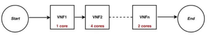
Figure 3: SFC Request Topology.
is said to be a single point of failure. It represents a group of machines that share a common power source and a network switch and it is defined based on the arrangement of the hardware. A machine, rack or pod can be a fault domain. In tree-based, switch-centric DC network topology such as Fat Tree and Spine and Leaf [26], we can define the fault domains easily. In Fat-Tree topologies, each pod is considered as one fault domain. In Spine-and-Leaf topologies, each leaf switch and the hosts connected to it form a fault domain.
On the contrary, it is not possible to define fault domains in server-centric DCs – such as Dcell and Bcube [27]. We therefore do not consider such topologies in our study.
2) Service Function Chains independence and
work-load: Public cloud DCs share the same physical
infras-tructure with heterogeneous services operated by multiple tenants. In this paper, we consider the case of tenants willing to deploy SFCs in the DC. An SFC is a group of virtual functions ordered in sequences to provide a service to an end user. Each function uses the output of the previous one in the chain as an input [1]. An SFC can be represented as a directed graph. Each node represents a virtual function annotated with its resource requirements (e.g., CPU, memory, etc.) while each edge represents a virtual link vLink annotated with its requirements (e.g., bandwidth). A virtual link logically represents the flow of traffic between two functions where the destination node (i.e., function) consumes the traffic generated by the origin node (i.e., function). If no traffic is directly exchanged between two functions, no vLink is defined. While in the general case SFCs can be arbitrary directed graphs, we restrict our work to the common case of directed acyclic graphs [28].
In this work, each function is dedicated to only one SFC, and an SFC is under the sole control of a single tenant. This assumption holds in case of public clouds, where tenants are independent actors and the DC operator considers functions as opaque virtual machines. If a function is implemented by using multiple instances of the same VM (e.g., because of processing limitations of a single host), we assume that the load is equally and instantaneously balanced between all the function instances, e.g., through LBaaS in OpenStack.
To preserve performance while sharing the same phys-ical hosts between many tenants, the total amount of the physical host resources is always larger than the sum of
the used resources by various VMs deployed on that host. As we do not consider the deployment phase of SFCs and given that we consider Fat-Tree and Spine-and-Leaf topologies in this paper, we can safely assume that the network provides infinite bandwidth w.r.t. SFCs demands.
3) Online Placement: In some specific private cloud
deployments, one can control the workload and thus apply offline optimization techniques to decide on the placement of virtual service chain functions in the data center. However, in the general case of a public cloud, the workload and the management of the infrastructure are handled by different independent entities (i.e., tenants and the cloud provider). As a result, the placement of SFCs must be determined in an online manner that is oblivious to future demands.
4) Robustness and Failure Model: We target the
place-ment of SFCs with robustness guarantees, where the k robustness level stands for the ability of an SFC to remain fully operational upon the failure of k entities of the infrastructure and without having to re-deploy or migrate virtual machines upon failures in order to guarantee zero downtime.
When a tenant requests the placement of a service function, it provides the service function graph with its required resources – the VM flavor for each chain function – and the SLA commitment for the chain (e.g., five nines).
Assuming a strict fail-stop failure model [29] with uncorrelated events and given the knowledge of its infras-tructure (MTBF and MTTR of the physical equipment), the SFC graph and subscribed duration, and the requested SLA commitment [23], the data center operator can deter-mine the maximum number of concomitant physical node failures that the chain may encounter during its lifetime.
IV. SFC PLACEMENT WITHROBUSTNESS
In this section, we propose a two-phase algorithm to place SFCs in a DC such that whenever a chain is deployed, it offers robustness guarantees. To avoid downtime upon failures in the physical infrastructure, we cannot rely on a reactive approach that would redeploy functions after failure detection [7]. Instead, we propose to account in advance for the potential fail-stop node failures that the chains may encounter during their life cycle.
To that aim, our algorithm replicates multiple times the chain and scales down each replica such that each replica has an equal fraction of the total load of the initial chain. In the remaining of this paper, we refer to such scaled down replicas with the term scaled replica. Our algorithm is called each time a request to install an SFC is received. Specifically, for a robustness level R, the algorithm determines how many scaled replicas to create for that SFC and where to deploy them within the data
Figure 4: Initial placement. Link capacity: 20 Mbps, Core per hosts:3
Figure 5: Final placement. Link capacity: 20 Mbps, Core per hosts:3
center such that the chain will be robust to at least R simultaneous fail-stop node failures without impairing the robustness guarantees of the chains already deployed. In other words, even if R nodes fail, every chain deployed in the data center will keep working at its nominal regime. To guarantee the isolation between scaled replicas of a chain, each replica of a chain is deployed in a different fault domain [30]. Also, as we assume a fail-stop failure model, at least R + 1 scaled replicas are needed to be robust to R failures. At first, the algorithm creates R + 1
scaled replicas1 and tries to find R + 1 fault domains
able to host the scaled replicas. If no solution exists, the algorithm is repeated for R + 2, R + 3,. . . , max iteration replicas until a solution is found. If a solution is found, the scaled replicas can effectively be deployed in the data center.
To determine whether or not a placement is possible for a given robustness level, the algorithm considers the normal committed resources, i.e., the minimum re-sources (e.g., cores, memory) that a compute node must dedicate to guarantee proper functioning under normal conditions (i.e., no failures) and the worst-case committed resources, i.e., the minimum number of resources required on compute nodes to guarantee proper functioning upon R simultaneous compute node failures impacting the chain.
1Each scaled replica is in charge of 1
R+1 chain load.
Figure 4 and Figure 5 illustrate the behavior of the algorithm with the deployment of a chain composed of two functions: the first function requires 4 cores, while the second one requires 2 cores and the flow between these two functions requires 30 Mbps to properly work, with the target of being robust to one node failure. Figure 4 shows the placement of the chain in a Fat-Tree data center where each node in the DC has 3 cores. Each replica receives 50% of the expected load, shown in red. After checking the robustness, the algorithm decides to split the chain since the first placement does not meet the robustness requirements because the worst-case commitment is not respected, as one failure would result in the need of 4 cores on the remaining hosts. Moreover, the physical network links cannot support more than 20 Mbps while in the worst-case the link requirement is 30 Mbps. The placement in Figure 5, depicted in green, meets the robustness level as when a node fails, one of the scaled replicas will fail but the other replicas will be able to temporarily support the whole load of the failed one as in the worst case each link needs to hold 5 Mbps more.
In order to find such a placement, we propose a two-step algorithm, listed in Algorithm 1. In the first two-step, SolveCPU(G, C, R, M ) solves the problem of placing the service function chain C on the DC topology G taking into account the required robustness level R and the functions CPU requirements (see Sec. IV-A). If the so-lution is empty, this means that no function placement can be found and the SFC request will be rejected. Otherwise, the result of this step corresponds to the set of mappings associating replica functions and the compute nodes on which they have to be deployed. In the second step, the obtained solution will be used as an input of Algorithm SolveBW(G, C, CP U -P lacement) in which each
vLink is mapped to one or more physical link(s), called
path(s), according to the bandwidth requirements, see Sec. IV-C. If all vLinks can be mapped, the service will be accepted and deployed on the DC network. Else, the service request will be rejected as the bandwidth requirements cannot be satisfied.
A. Node placement
In the function placement step (see Algorithm 2), the solve_placement(S, G, n) function consid-ers two graphs: the DC topology graph G and the scaled replica graph S where the scale_down(C, n) function computes the scaled replica scheme, i.e., an annotated graph representing the scaled down chain, for a chain C if it is equally distributed over n scaled replicas (see Sec. IV-B). The goal of the function solve_placement(S, G, n) is to project n func-tion replicas of the scaled replica graph S on the topology
Algorithm 1: Robust placement algorithm Input: Physical network Graph: G
C ∈ Chains Robustness level: R
Maximum number of replicas: max iterations M = max iterations
CPU Placement= SolveCPU(G, C, R, M) if CPU Placement=φ then
Error(Impossible to place the chain NFs) else
BW Placement= SolveBW(G, C, CPU Placement) if BW Placement=φ then
Error(Impossible to place the chain vLinks) else
deploy(G, CPU Placement, BW Placement)
Algorithm 2: SolveCPU algorithm Input: Physical network Graph: G
C ∈ Chains
Scaled chain replica graph: S Robustness level: R
Maximum number of replicas: M n = R + 1
CPU Placement = φ
while CPU Placement = φ and M > 0 do S = scale_down(C, n)
CPU Placement = solve_placement(S, G, n)
n = n + 1 M = M -1
return(CPU Placement)
Algorithm 3: SolveBW algorithm Input: Physical network Graph: G
C ∈ Chains
CPU Placement: Placement of SFCs nodes BW Placement = φ
foreach replica placement ∈ CPU Placement do foreach vLink do paths = all_shortest_paths(G, S, D) path = valid_path(paths) if path 6= φ then BW Placement ] path else BW Placement = φ break return(BW Placement)
graph G with respect to the physical and chain node constraints.
For each fault domain, solve_placement(S, G, n) tries to find a solution for the linear problem defined in Sec. IV-A1, which aims at finding a placement for the scale replica graph in the fault domain while respecting VNFs requirements. If there are at least n fault domains with a solution to the problem, then any n of them is a solution to our robust placement problem. Otherwise, no solution is found and an empty set is returned.
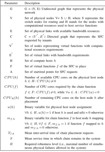
Parameter Description
G G = (V, E) Undirected graph that represents the physical network
V Set of physical nodes V= S ∪ H, where S represents the switch nodes for routing and H stands for the nodes with computational resources used to host service functions E Set of physical links with available bandwidth resources C C = (V0, E0) Directed graph that represents the SFC
requested by tenants
V0 Set of nodes representing virtual functions with computa-tional resources requirements
E0 Set of virtual links with bandwidth requirements H Set of compute hosts h
F Set of virtual functions f of the SFC to place A Set of start/end points for SFC requests
CP U (h) Number of available CPU cores on the physical host node h ∈ H: CP U (h) 6= 0
CP U (f ) Number of CPU cores required by the chain function f ∈ F : CP U (f ) 6= 0, while ∀a ∈ A : CP U (a) = 0 CP UR(h) Number of remaining CPU cores on the host node h after
placement
u(h) Binary variable for physical host node assignment: ∀h ∈ H, u(h) = 1 if host h is used and u(h) = 0 otherwise mf,h Binary variable for chain function f to host node h mapping
∀h ∈ H, ∀f ∈ F, mf,h= 1 if function f mapped to h
and mf,h= 0 otherwise.
TIA Mean inter-arrival time of chain placement requests
S Mean service time in which chain remains in the system R Required robustness level (i.e., maximal number of
simulta-neous physical failures allowed in the system) Table I: Notations used in the paper 1) ILP Approach:
The online robust placement problem can be formulated as an Integer Linear Programming (ILP).
Given the physical network undirected graph G = (V, E) and the service function chain directed graph C = (V0, E0), Table I summarizes all the variables that define the problem and other variables used in our model formulation to place one particular service chain.
To solve the placement problem, we introduce two binary decision variables of different types:
(1) Bin used variables. u(h) indicates whether physical host h is used.
(2) Item assignment variables. mf,h indicates whether function f is mapped to physical host h.
2) ILP Formulation: Objective: max min ∀h∈H(CP UR(h)) (1) Subject to: Assignment constraints: ∀f ∈ F, X h∈H mf,h= 1 (2) ∀h ∈ H, u(h) = 1 if X f ∈F mf,h≥ 1 (3) Capacity constraints: ∀h ∈ H, X f ∈F mf,h. CP U (f ) ≤ CP U (h) (4) CP UR(h) = CP U (h) − X f ∈F mf,h. CP U (f ) (5) 3) ILP Explanation:
Normally, to implement their policies, operators must define their objective function; for example, service providers may want to reduce the placement cost or the energy consumption by minimizing the number of used hosts involved in the placement.
For our model, the optimization objective presented in Equation 1 aims at maximizing the minimum remaining CPU resources on each physical host in the network. This objective corresponds to spreading the load over all the hosts in the DC.
Constraint (2) guarantees that each virtual function is assigned only once while Constraint (3) accounts for the used hosts. Constraints (4) and (5) ensure that hosts are not over-committed and account for their usage, where CP U (h) is the amount of available CPU cores of the physical host (h) and CP U (f ) is the number of CPU cores required by function (f ).
B. Replication Model
When a new SC request is received, in order to fulfill its required robustness level, the chain is replicated in additional chains; each one is called a scaled replica. The idea behind replication is to exactly replicate the functionality of a chain such that the load can be balanced equally among all replicas. Each replica requires only a fraction of the initial required resources. More precisely, each scaled replica requires 1nof the resources of the main chain if the chain has been replicated n times.
The scale_down(C, n) function computes an an-notated graph representing the same graph as C but where the resources associated to each node and link have been scaled down by a factor n. It is worth noting that some resources are discrete or cannot go below some threshold, meaning that the function may not be linear. For example, if the unit of core reservation is 1 core, then scaling down 3 times a resource that requires 2 cores will result in requiring 1 core on each replica.
C. vLink placement
The BW problem (see algorithm 3) represents the last step in our placement process. Its objective is to map virtual links to actual network paths, based on the placement of virtual network functions obtained from the
CPU placementstep.
For each virtual link between two functions in each service scaled replica, it retrieves all the shortest paths between the source and the destination physical servers that host these two functions (i.e., the traffic traversing a vLink may cross several physical links). Among these shortest paths, the valid_path(paths) function tests the shortest paths randomly in order to find one path that can hold the required traffic. Thus, for each vLink it tries to find one valid shortest path. If none exists, it returns an empty set, which means that the placement will be rejected. Else, this accepted path will be ap-pended to the list of accepted paths. The set of vLinks placement (BW Placement) is returned so that the chain can ultimately be deployed by using the Deploy(G,
CPU_Placement, BW_Placement) function (i.e.,
virtual functions are instantiated and network routes are installed in the switches).
D. Discussion
Defining the optimal of an online problem is always a challenge as it potentially requires solving at any time t a problem whose optimal depends on time t0 > t for which the knowledge is incomplete or absent.
In this paper we aim at finding, in an online manner, placements for SFCs in large data centers that guarantee robustness and with the objective of maximizing the SFC request acceptance ratio. Our problem is a variation of the online job shop scheduling problem with multiple operations (i.e., functions) per job (i.e., SFCs) for a number of resources > 2 (i.e., servers and links), with penalties and unknown jobs arrival and duration. This particular problem is reputed to be NP-complete [31], [32], [33]. To the best of our knowledge, no bounded heuristic is known for this problem.
We approximate this problem with a two-step algo-rithm to be executed at each SFC request arrival. The first step finds an optimal feasible placement for the different
constituting functions of the service function chain within one fault domain. A feasible placement is a placement for which there is no over-commitment of CPU cores on the server (i.e., a function never shares a core with another function and the number of consumed cores on a server does not exceed the number of cores of the server) and an optimal placement is a placement for which each server maximizes its number of available cores for future potential function placements. Even though this is a variation of the Knapsack problem, which optimization is NP-hard, in practice as chains are small and as fault domains do not face high contention situations, finding the optimal is feasible in short time (see Sec. V for practical examples on very large data centers). Once the placement of functions is decided at the first step, regardless of the network situation, a feasible path is decided in the second step of the algorithm in polynomial time using shortest path computation exploration.
It is worth it to mention that our approximation al-gorithm does not guarantee to maximize the acceptance ratio of SFC requests. However, it approximates it by ensuring that after each placement, each server will of-fer the maximum number of free CPU cores. In tight scenarios with high contention, this would be far from optimal. However, in practical cases with limited resource contention, this approach offers both good acceptance ratios and acceptable computation times, as demonstrated in Sec. V.
V. EVALUATION
In the following we evaluate the robust SFC placement algorithm introduced in Sec. IV.
A. Simulation Environment
We have implemented a discrete event simulator in
Python.2 In the evaluation, requests to deploy a chain
are independent and follow an exponential distribution
of mean TIA, where TIA is the mean inter-arrival time
of chain placement requests (measured in arbitrary time unit). Service function chains have a service time of S time units, i.e., the time the chain remains in the system is randomly selected following an exponential distribution of mean S. An SFC that cannot be deployed in the topology is lost, i.e., there is no further request for the rejected chain. In total, our synthetic workload for the simulations contains 1,000 service request arrivals made of 20 arbitrary chains.
In the simulations, every SFC forms a linear chain of functions put in sequence. Each chain has one single starting point and one single destination point. The num-ber of functions between the two endpoints is selected
2All the data and scripts used in this paper are available on
https://team.inria.fr/diana/IEEEAccess/.
uniformly between 2 and 5, based on typical use cases of networks chains [34], and the requirements of each function in terms of cores is 1, 2, 4, or 8 inspired by the most common Amazon EC2 instance types [35]. Each vLink consumes 250 Mbps.
Simulations are performed on the three following topologies: (i) 48-Fat-Tree topology, with 48 pods, each of them having 576 hosts for a total of 27,648 hosts;
(ii) Spine-and-Leaf topology, a network with 48 leaf
switches directly connected to 512 hosts for a total of 24,576 hosts, and generic topology, which is built from 54 switches connected to each other and each one of them is connected to 512 host nodes. Each switch represents one fault domain with a total number of 27,648 hosts in this topology. The three topologies are representative of today’s data centers and are directly comparable (they have either the same number of fault domains, or the same number of hosts and cores). Resources are homogeneous in the topologies: all hosts have the same number of cores (4 cores per host); all links between aggregation and core switches in the Fat Tree and between leaf and spine switches are 10 Gbps links; and hosts are connected to their ToR/leaf switch through a 1 Gbps link.
To ensure that we are not studying transient results with the workload, we verified that the whole system is in steady state before running a workload of 1,000
service requests. We fixed TIA to the value 0.01 such
that in the ideal case, the Fat-Tree topology would be loaded at about 90%. Because of space limitations, we fixed R to be equal for each chain in a run, however the algorithm allows using a different value of R for each chain. Our simulations have been performed in
Grid’5000.3 In addition, all the following experiments
were repeated 10 times using ten different workloads with the same parameters.
B. Acceptance Ratio
In this section we study the impact of required robustness level R on the ability to satisfy SFCs placement requests. To that aim, we use the acceptance
ratiodefined as the number of accepted requests over the
total number of requests.
Figure 6 shows the evolution of the acceptance ratio with the 3 different large data-center topologies described above (i.e., Fat Tree, Spine and Leaf, and Generic) w.r.t. the robustness level. The particular choice of topologies permits to evaluate the impact of the number of fault do-mains and the number of core resources on the acceptance ratio. Here we distinguish between two configurations for
3We ran the experiments on the site located in Rennes,
0 1 2 3 4 Robustness Level 0.4 0.5 0.6 0.7 0.8 0.9 1.0 Acceptance Ratio Optimal, relax-R Optimal, strict-R FFD, relax-R FFD, strict-R
(a) 48-F at-T ree Topology
0 1 2 3 4 Robustness Level 0.4 0.5 0.6 0.7 0.8 0.9 1.0 Acceptance Ratio Optimal, relax-R Optimal, strict-R FFD, relax-R FFD, strict-R (b) Spine-and-Leaf Topology 0 1 2 3 4 Robustness Level 0.4 0.5 0.6 0.7 0.8 0.9 1.0 Acceptance Ratio Optimal, relax-R Optimal, strict-R FFD, relax-R FFD, strict-R (c) Generic Topology Figure 6: Comparing acceptance ratio of the Optimal solution and Greedy FFD for 3 different topologies with 3 robustness levels.
0 2 4 6 8
Number of scaled replicas
0.0 0.2 0.4 0.6 0.8 1.0 ECDF R= 0 R= 1 R= 2 R= 3
(a) 48-F at-T ree Topology
0 2 4 6 8
Number of scaled replicas
0.0 0.2 0.4 0.6 0.8 1.0 ECDF R= 0 R= 1 R= 2 R= 3 (b) Spine-and-Leaf Topology 0 2 4 6 8
Number of scaled replicas
0.0 0.2 0.4 0.6 0.8 1.0 ECDF R= 0 R= 1 R= 2 R= 3 (c) Generic Topology Figure 7: The ECDF for the number of created replicas with 3 robustness levels with 3 different topologies for the optimal algorithm.
0 2 4 6 8
Number of scaled replicas
0.0 0.2 0.4 0.6 0.8 1.0 ECDF R= 0 R= 1 R= 2 R= 3
(a) 48-F at-T ree Topology
0 2 4 6 8
Number of scaled replicas
0.0 0.2 0.4 0.6 0.8 1.0 ECDF R= 0 R= 1 R= 2 R= 3 (b) Spine-and-Leaf Topology 0 2 4 6 8
Number of scaled replicas
0.0 0.2 0.4 0.6 0.8 1.0 ECDF R= 0 R= 1 R= 2 R= 3 (c) Generic Topology Figure 8: ECDF of the number of created replicas with 3 robustness levels with 3 different topologies for the FFD algorithm.
0 2 4 6 8 10 12 14 16 18 20 22 24 26 Number of requested CPU cores 0.0 0.1 0.2 0.3 0.4 0.5 0.6 0.7 0.8 0.9 1.0 Acceptance Probability relax-R= 1 relax-R= 2 relax-R= 3 strict-R= 1 strict-R= 2 strict-R= 3
(a) 48-F at-T ree Topology
0 2 4 6 8 10 12 14 16 18 20 22 24 26 Number of requested CPU cores 0.0 0.1 0.2 0.3 0.4 0.5 0.6 0.7 0.8 0.9 1.0 Acceptance Probability relax-R= 1 relax-R= 2 relax-R= 3 strict-R= 1 strict-R= 2 strict-R= 3 (b) Spine-and-Leaf Topology 0 2 4 6 8 10 12 14 16 18 20 22 24 26 Number of requested CPU cores 0.0 0.1 0.2 0.3 0.4 0.5 0.6 0.7 0.8 0.9 1.0 Acceptance Probability relax-R= 1 relax-R= 2 relax-R= 3 strict-R= 1 strict-R= 2 strict-R= 3 (c) Generic Topology Figure 9: Probability of service chain being accepted based on the number of requested CPU cores for different robustness levels with 3 different topologies using the Optimal algorithm.
0 2 4 6 8 10 12 14 16 18 20 22 24 26 Number of requested CPU cores 0.0 0.1 0.2 0.3 0.4 0.5 0.6 0.7 0.8 0.9 1.0 Acceptance Probability relax-R= 1 relax-R= 2 relax-R= 3 strict-R= 1 strict-R= 2 strict-R= 3
(a) 48-F at-T ree Topology
0 2 4 6 8 10 12 14 16 18 20 22 24 26 Number of requested CPU cores 0.0 0.1 0.2 0.3 0.4 0.5 0.6 0.7 0.8 0.9 1.0 Acceptance Probability relax-R= 1 relax-R= 2 relax-R= 3 strict-R= 1 strict-R= 2 strict-R= 3 (b) Spine-and-Leaf Topology 0 2 4 6 8 10 12 14 16 18 20 22 24 26 Number of requested CPU cores 0.0 0.1 0.2 0.3 0.4 0.5 0.6 0.7 0.8 0.9 1.0 Acceptance Probability relax-R= 1 relax-R= 2 relax-R= 3 strict-R= 1 strict-R= 2 strict-R= 3 (c) Generic Topology Figure 10: Probability of service chain being accepted based on the number of requested CPU cores for different robustness levels with 3 different topologies using the FFD algorithm.
our placement algorithm: in strict we impose the number of scaled replicas to be exactly R + 1 while in relax the number of scaled replicas can be any integer value between R + 1 and (R + 1) · 2.
Moreover, we consider two different function place-ment algorithms: (i) Optimal solves the optimization problem specified in Sec. IV-A1 and (ii) FFD uses the well-known First-Fit Decreasing (FFD) greedy heuris-tic [19], [20].
In general we can expect that the acceptance ratio decreases when the robustness level increases as increas-ing robustness means dedicatincreas-ing more resource to each function. This trend is confirmed by Figure 6. One can also expect to have better acceptance ratio with Optimal than with FFD but even if it is true, in practice the difference is negligible as shown in Figure 6. While the impact of R and the impact of using FFD instead of the optimal are evident to forecast, it is much harder to speculate on the impact of being strict in the number of scaled replicas or not (i.e., strict versus relax). On the
one hand being strict reduces the amount of resources used for each deployed function and should thus give more space for other functions. On the other hand, not being strict allows splitting chains further such that the replicas can be “squeezed” in servers with less available resources. This duality is clearly visible in Figure 6. For R = 0 we observe that by being strict, only around 81% of the requests can be satisfied while allowing more than R + 1 scaled replicas allows to satisfy all demands. The difference between the two scenarios can be explained by the fact that we intentionally made the workload such that in 19% of the demands at least one function in the chain requires 8 cores. As the servers only have 4 cores, it is then impossible to install them unless we allow using multiple replicas (which is the case for relax with R = 0 case but not for strict with R = 0 case). This first observation confirms that allowing more scaled replicas gives more flexibility in finding a placement solution. This trend is clearly visible, except for R = 1 where we can see that in the Spine-and-Leaf topology (see
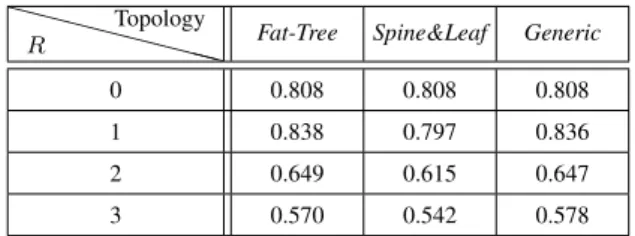
XX XX XXX X R Topology
Fat-Tree Spine&Leaf Generic
0 0.808 0.808 0.808
1 0.838 0.797 0.836
2 0.649 0.615 0.647
3 0.570 0.542 0.578
Table II: Similarity Index between the strict and relax configu-ration for the three different topologies
Figure 6(b)) strict outperforms relax. The reason of this difference lays in the fact that in the strict case it is still impossible to install the 19% of requests with at least one function requiring 8 cores. Indeed, in case of failure the only remaining replica would still require 8 cores, while under normal operations each of the two replicas only needs 4 cores. As these chains are not installed, they leave enough room for the others to be installed. On the contrary, with the relax case, these requests can be satisfied but consume a substantial amount of resources; they need at least 3 scaled replicas to be deployed, which prevents other chains to be installed, hence reducing the overall acceptance ratio.
It is worth mentioning that if the acceptance ratios for R = 1 seem to be identical for both cases in the
Fat-Tree and the Generic topologies, they are actually
slightly different and the similitude is only an artifact of the workloads and topologies that we used. Indeed, even though the acceptance ratios are very close, the placements are largely different as shown by the Jaccard similarity coefficient [36] of only 0.84 (see Table II). In general, the dissimilarity of placements increases with R. For example, the Jaccard similarity coefficient is as low as 0.54 in the Spine-and-Leaf topology when R = 3.
Keeping in mind that the Fat-Tree topology has the same number of fault domains as the Spine-and-Leaf topology but has more cores in total, and that the Generic topology has the same amount of cores as the Fat-Tree topology but with more fault domains, the comparison between the 3 topologies leads us to conclude that as long as the number of fault domains is larger than max iterations, the number of cores is what influences the most the acceptance ratio.
To complement the acceptance ratio study, Figure 7 and Figure 8 provide the empirical cumulative distribution functions of the number of scaled replicas created when placing SFCs while guaranteeing different robustness levels for the three different topologies with the relax configuration. As we consider highly loaded topologies, most of the time R + 1 or R + 2 replicas are enough to ensure robustness level of R and we seldom reach the (R + 1) · 2 limit, as most resources are consumed by
replicas of other chains. Moreover, if we take a careful look at the number of scaled replicas for R = 0, about 80% of services are placed with only 1 replica which is the same value of the acceptance ratio for R = 0 with the strict configuration in Figure 6 – and about 20% with two scaled replicas. This extra replica leads to an increase in the acceptance ratio where the acceptance ratio reaches 1 when we relax the replication (in Figure 6). If we study the probability of a chain to be accepted as a function of its requested number of cores (see Figure 9 and Figure 10), we see that our algorithm favors the installation of small chains over large ones, particularly for large values of R.4
C. Acceptance ratio in case of network congestion In Sec. V-B when a request is rejected, the reason is always that the placement algorithm was not able to find hosts with enough free cores, and never because of the network capacity. This is because each host is connected to the network with a 1 Gbps link and has 4 cores. As our algorithm cannot overcommit hosts we know that a host will never run more than 4 functions simultaneously. Therefore, as each vLink requests 250 Mbps, the traffic to or from a host never exceeds 1 Gbps, which is not enough to overload the host links and as we use clos topologies, it means that the backbone network also cannot be overloaded.
In this section, we aim at stressing the network as well as the hosts. To that aim we keep the same workload as in Sec. V-B but vLinks request 500 Mbps instead of 250 Mbps, which may result in network congestion.
Figure 11 shows the acceptance ratio for this new scenario (labeled w/ congestion) and compares it to pre-vious results (labeled as w/o congestion). For R = 0, the acceptance ratio drops by 50% or more because the network cannot handle the load. Even though the drop is important in both cases, as the relax option allows to create multiple replicas, it outperforms the strict option. However, as soon as R ≥ 1, we obtain the same results than in Sec. V-B as we fall back in a case with no network congestion because when every function uses at least 2 scaled replicas, the network demand for a host will not exceed 1 Gbps.
D. SFC Request Placement Time
To be acceptable, the time spent on finding a placement must be at most of the same order of magnitude as the deployment of the VMs themselves in order not to impact the deployment time of a service.
4We can explain that the figures do not show smooth decreasing lines
by the fact that we only used 20 different chain types, which is not enough to cover all potential cases.
0 1 2 3 4 Robustness Level 0.3 0.4 0.5 0.6 0.7 0.8 0.9 1.0 Acceptance Ratio
relax-R, w/o congestion strict-R, w/o congestion relax-R, w/ congestion strict-R, w/ congestion
(a) 48-F at-T ree Topology
0 1 2 3 4 Robustness Level 0.3 0.4 0.5 0.6 0.7 0.8 0.9 1.0 Acceptance Ratio
relax-R, w/o congestion strict-R, w/o congestion relax-R, w/ congestion strict-R, w/ congestion (b) Spine-and-Leaf Topology 0 1 2 3 4 Robustness Level 0.3 0.4 0.5 0.6 0.7 0.8 0.9 1.0 Acceptance Ratio
relax-R, w/o congestion strict-R, w/o congestion relax-R, w/ congestion strict-R, w/ congestion
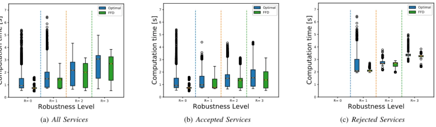
(c) Generic Topology Figure 11: Comparing acceptance ratio of the Optimal solution for the different topologies with 3 robustness levels for the two workloads. R= 0 R= 1 R= 2 R= 3 Robustness Level 0 1 2 3 4 5 6 7 Computation time [s] Optimal FFD
(a) All Services
R= 0 R= 1 R= 2 R= 3 Robustness Level 0 1 2 3 4 5 6 7 Computation time [s] Optimal FFD (b) Accepted Services R= 0 R= 1 R= 2 R= 3 Robustness Level 0 1 2 3 4 5 6 7 Computation time [s] Optimal FFD (c) Rejected Services Figure 12: Algorithm computation time with different robustness levels for the Fat-Tree topology with relax configuration.
Figure 12 shows the whisker plot of all computation times of Algorithm 1 for the harder instance of the problem, namely the Fat-Tree topology with the relax scheme for both the optimal and FFD. The simulations were performed in Grid5000 [37] on the Rennes site in fall 2018.
We make the distinction between the time elapsed when requests result in an effective placement (Accepted Services) in Figure 12(b) and when they do not (Rejected Services) in Figure 12(c), while Figure 12(a) (All Services) aggregates computation time for all requests, regardless of the outcome.
The computation time increases rather linearly with the robustness level and never exceeds a few seconds, which is negligible compared to the typical time necessary to deploy and boot virtual functions in data centers [38]. This rather linear increase is because an increase of R incurs a proportional increase of the number of iterations (max iterations) and the number of required fault domains (n in solve_placement(S, G, n)) but does not change the size of the solve_placement problem (see Sec. IV) as the size of the fault domain is not impacted
by R.
Furthermore, for both figures, the computation time is longer when requests are rejected than when they are accepted as the rejection of a service request can only be decided after having tested all the allowed number of replicas (i.e., max iterations). Note that all demands are accepted for the relax case when R = 0 which explains the absence of observations for R = 0 in Figure 12(c).
Regarding accepted services, (e.g., for R = 1 in Fig-ure 12(b), the spread between median and upper quartile is smaller than the spread between median and lower quartile as most of placements require R + 1 or R + 2 replicas only. However, in some scenarios, the algorithm is iterated until the maximum allowed iterations in order to find this valid placement, which explains having the outliers in the Figure 12.
Interestingly, even though the execution time is shorter when FFD is used, it remains of the same order of magnitude as when the optimal placement is used instead.
VI. CONCLUSION
In this paper we proposed a solution to deploy SFCs in public cloud data centers with guarantees that chains are robust to k independent fail-stop node failures. The idea is to replicate the chain in multiple independent locations in the data center and to balance the load between these replicas based on their availability in order to prevent downtime upon failures in the physical infrastructure.
To that aim, we proposed an online two-phase algo-rithm that determines the number of replicas and where to place them to guarantee some robustness level based on an ILP solution or its approximation. We extensively eval-uated this algorithm on very large data center networks – up to 30,528 nodes – to assess the feasibility of our proposition in very large-scale data centers. We showed that approximating the solution with the widely used FFD technique was not mandatory as optimal placement of independent replicas was feasible in acceptable time, which allows placement decisions to be made on-demand and without prior knowledge on the DC workload. We studied the impact of the choice of the topology and the expected robustness level on the acceptance ratio and on the placement computation time. It shows that when the data center is sufficiently provisioned, our algorithm is able to provide a robust placement for all the chains. On the contrary, when the DC lacks resources, the algorithm tends to favor shorter chains as they consume less re-sources, giving them more placement options.
We are currently working on defining a generic stochastic model to automatically translate SLA require-ments expressed in maximum downtime into robustness levels. In parallel, we are exploring how to integrate our mechanism in OpenStack.
ACKNOWLEDGMENT
This work is funded by the French ANR through the Investments for the Future Program under grant ANR-11-LABX-0031-01. Experiments presented in this paper were carried out using the Grid’5000 testbed, supported by a scientific interest group hosted by Inria and including CNRS, RENATER and several Universities as well as other organizations (see https://www.grid5000.fr).
REFERENCES
[1] J. M. Halpern and C. Pignataro, “Service Function Chaining (SFC) Architecture,” RFC 7665, Oct. 2015. [Online]. Available: https://rfc-editor.org/rfc/rfc7665.txt [2] R. Mijumbi, J. Serrat, J. Gorricho, N. Bouten, F. De Turck,
and R. Boutaba, “Network function virtualization: State-of-the-art and research challenges,” IEEE Communications Surveys Tutorials, vol. 18, no. 1, pp. 236–262, Firstquarter 2016.
[3] H. Moens and F. D. Turck, “Vnf-p: A model for efficient placement of virtualized network functions,” in 10th Inter-national Conference on Network and Service Management (CNSM) and Workshop, Nov 2014, pp. 418–423. [4] S. Mehraghdam, M. Keller, and H. Karl, “Specifying
and placing chains of virtual network functions,” in 2014 IEEE 3rd International Conference on Cloud Networking (CLOUDNET), Oct 2014, pp. 7–13.
[5] M. F. Bari, S. R. Chowdhury, R. Ahmed, and R. Boutaba, “On orchestrating virtual network functions,” in 2015 11th International Conference on Network and Service Manage-ment (CNSM), Nov 2015, pp. 50–56.
[6] R. Cohen, L. Lewin-Eytan, J. S. Naor, and D. Raz, “Near optimal placement of virtual network functions,” in IEEE Conference on Computer Communications (INFOCOM), April 2015, pp. 1346–1354.
[7] A. Marotta and A. Kassler, “A power efficient and robust virtual network functions placement problem,” in 2016 28th International Teletraffic Congress (ITC 28), vol. 01, Sep. 2016, pp. 331–339.
[8] P. Gill, N. Jain, and N. Nagappan, “Understanding network failures in data centers: Measurement, analysis, and implications,” in Proceedings of the ACM SIGCOMM 2011 Conference. New York, NY, USA: ACM, 2011, pp. 350–361. [Online]. Available: http://doi.acm.org/10.1145/ 2018436.2018477
[9] H. S. Gunawi, M. Hao, T. Leesatapornwongsa, T. Patana-anake, T. Do, J. Adityatama, K. J. Eliazar, A. Laksono, J. F. Lukman, V. Martin, and A. D. Satria, “What bugs live in the cloud? a study of 3000+ issues in cloud systems,” in Proceedings of the ACM Symposium on Cloud Computing (SOCC). New York, NY, USA: ACM, 2014, pp. 7:1–7:14. [Online]. Available: http: //doi.acm.org/10.1145/2670979.2670986
[10] R. Potharaju and N. Jain, “Demystifying the dark side of the middle: A field study of middlebox failures in datacenters,” in Proceedings of the 2013 Conference on Internet Measurement Conference, ser. IMC ’13. New York, NY, USA: ACM, 2013, pp. 9–22. [Online]. Available: http://doi.acm.org/10.1145/2504730.2504737 [11] B. Han, V. Gopalakrishnan, L. Ji, and S. Lee, “Network
function virtualization: Challenges and opportunities for innovations,” IEEE Communications Magazine, vol. 53, no. 2, pp. 90–97, Feb 2015.
[12] S. G. Kulkarni, G. Liu, K. K. Ramakrishnan, M. Arumaithurai, T. Wood, and X. Fu, “Reinforce: Achieving efficient failure resiliency for network function virtualization based services,” in Proceedings of the 14th International Conference on Emerging Networking EXperiments and Technologies (CoNEXT). New York, NY, USA: ACM, 2018, pp. 41–53. [Online]. Available: http://doi.acm.org/10.1145/3281411.3281441
[13] F. Machida, , and Y. Maeno, “Redundant virtual machine placement for fault-tolerant consolidated server clusters,” in 2010 IEEE Network Operations and Management Sym-posium (NOMS), April 2010, pp. 32–39.
[14] E. Bin, O. Biran, O. Boni, E. Hadad, E. K. Kolodner, Y. Moatti, and D. H. Lorenz, “Guaranteeing high avail-ability goals for virtual machine placement,” in 2011 31st International Conference on Distributed Computing Systems (ICDCS), June 2011, pp. 700–709.
[15] X. Wang, C. Wu, F. Le, A. Liu, Z. Li, and F. Lau, “Online VNF scaling in datacenters,” in 2016 IEEE 9th International Conference on Cloud Computing (CLOUD), June 2016, pp. 140–147.
[16] A. Mohammadkhan, S. Ghapani, G. Liu, W. Zhang, K. K. Ramakrishnan, and T. Wood, “Virtual function placement and traffic steering in flexible and dynamic software de-fined networks,” in The 21st IEEE International Workshop on Local and Metropolitan Area Networks (LANMAN), April 2015, pp. 1–6.
[17] J. Fan, C. Guan, K. Ren, and C. Qiao, “Guaranteeing availability for network function virtualization with geo-graphic redundancy deployment,” University of Buffalo, Tech. Rep., 2015.
[18] K. Li, H. Zheng, and J. Wu, “Migration-based virtual machine placement in cloud systems,” in 2013 IEEE 2nd International Conference on Cloud Networking (ClOUD-NET), Nov 2013, pp. 83–90.
[19] Q. Zhang, Y. Xiao, F. Liu, J. C. S. Lui, J. Guo, and T. Wang, “Joint optimization of chain placement and request scheduling for network function virtualization,” in 2017 IEEE 37th International Conference on Distributed Computing Systems (ICDCS), June 2017, pp. 731–741. [20] D. Bhamare, M. Samaka, A. Erbad, R. Jain, L. Gupta, and
H. A. Chan, “Optimal virtual network function placement in multi-cloud service function chaining architecture,” Computer Communications, vol. 102, pp. 1 – 16, 2017. [Online]. Available: http://www.sciencedirect.com/science/ article/pii/S0140366417301901
[21] C. Lin, P. Liu, and J. Wu, “Energy-efficient virtual machine provision algorithms for cloud systems,” in 2011 Fourth IEEE International Conference on Utility and Cloud Com-puting (UCC), Dec 2011, pp. 81–88.
[22] K. Su, L. Xu, C. Chen, W. Chen, and Z. Wang, “Affinity and conflict-aware placement of virtual machines in het-erogeneous data centers,” in 2015 IEEE Twelfth Interna-tional Symposium on Autonomous Decentralized Systems (ISADS), March 2015, pp. 289–294.
[23] G. Moualla, T. Turletti, and D. Saucez, “An availability-aware sfc placement algorithm for fat-tree data centers,” in 2018 IEEE 7th International Conference on Cloud Networking (CLOUDNET), Oct 2018, pp. 1–4.
[24] A. Headquarters, “Cisco data center infrastructure 2.5 de-sign guide,” in Cisco Validated Dede-sign I. Cisco Systems, Inc, 2007.
[25] M. Al-Fares, A. Loukissas, and A. Vahdat, “A scalable, commodity data center network architecture,” SIGCOMM Comput. Commun. Rev. (CCR), vol. 38, no. 4, pp. 63–74, Aug. 2008. [Online]. Available: http://doi.acm.org/ 10.1145/1402946.1402967
[26] E. Banks, “Data center network design moves from tree to leaf,” SearchDataCenter, TechTar-get, Packet Pushers Interactive, 2016. [Online]. Available: https://searchdatacenter.techtarget.com/feature/ Data-center-network-design-moves-from-tree-to-leaf [27] C. Wu and R. Buyya, ”Cloud Data Centers and Cost
Modeling: A Complete Guide To Planning, Designing and Building a Cloud Data Center”, 1st ed. Morgan Kauf-mann Publishers Inc., 2015, ISBN-13: 978-0128014134. [28] M. C. Luizelli, L. R. Bays, L. S. Buriol, M. P. Barcellos,
and L. P. Gaspary, “Piecing together the NFV provisioning puzzle: Efficient placement and chaining of virtual network functions,” in 2015 IFIP/IEEE International Symposium on Integrated Network Management (IM), May 2015, pp. 98– 106.
[29] F. B. Schneider, “Byzantine generals in action: Implementing fail-stop processors,” ACM Trans. Comput. Syst., vol. 2, no. 2, pp. 145–154, May 1984. [Online]. Available: http://doi.acm.org/10.1145/190.357399 [30] L. E. Li, V. Liaghat, H. Zhao, M. Hajiaghayi, D. Li,
G. Wilfong, Y. R. Yang, and C. Guo, “Pace: Policy-aware application cloud embedding,” in IEEE Conference on Computer Communications (INFOCOM), April 2013, pp. 638–646.
[31] M. R. Garey, D. S. Johnson, and R. Sethi, “The complexity of flowshop and jobshop scheduling,” Mathematics of operations research, vol. 1, no. 2, pp. 117–129, 1976. [32] R. M. Karp, “On the computational complexity of
com-binatorial problems,” Networks, vol. 5, no. 1, pp. 45–68, 1975.
[33] R. J. M. Vaessens, “Generalized job shop scheduling: com-plexity and local search,” Technische Universiteit Eind-hoven, PhD Thesis, 1995.
[34] W. Liu, H. Li, O. Huang, M. Boucadair, N. Leymann, Z. Cao, Q. Sun, and C. Pham, “Service function chaining (sfc) general use cases,” Work in progress, IETF Secre-tariat, Internet-Draft draft-liu-sfc-use-cases-08, 2014. [35] “Amazon ec2 instance types.” [Online]. Available: https:
//aws.amazon.com/ec2/instance-types/
[36] P. Jaccard, “Distribution de la flore alpine dans le bassin des Dranses et dans quelques r´egions voisines,” Bulletin de la Soci´et´e Vaudoise des Sciences Naturelles, vol. 37, pp. 241 – 272, 1901.
[37] F. Cappello, E. Caron, M. Dayde, F. Desprez, Y. Jegou, P. Primet, E. Jeannot, S. Lanteri, J. Leduc, N. Melab, G. Mornet, R. Namyst, B. Quetier, and O. Richard, “Grid’5000: a large scale and highly reconfigurable grid experimental testbed,” in The 6th IEEE/ACM International Workshop on Grid Computing (GRID), Nov 2005, p. 8 pp.
[38] M. Mao and M. Humphrey, “A performance study on the VM startup time in the cloud,” in 2012 IEEE Fifth International Conference on Cloud Computing (CLOUD), June 2012, pp. 423–430.