SYSTEM DESIGN DECOMPOSITION
by
Daniel Charles Dobbs
S.B., Mechanical Engineering, 1998 Massachusetts Institute of Technology
Submitted to the Department of Mechanical Engineering in partial fulfillment of the Requirements for the Degrees of MASTER OF SCIENCE IN MECHANICAL ENGINEERING
and
MASTER OF SCIENCE IN TECHNOLOGY AND POLICY at the
Massachusetts Institute of Technology September 2000
D 2000 Massachusetts Institute of Technology. All rights reserved
BARKER MASSACHUSETTS INSTITUTE OF TECHNOLOGY
JUL 16
2001
LIBRARIES Signature of AuthorDepartment of Mechanical Engineering August 18, 2000
Certified by
Certified by
Accepted by
David S. Cochran Assistant Professor of Mechanical Engineering Thesis Supervisor
(2
Daniel E. Hatings Director, Technology and Policy Program Professor of Engineering Systems & Aeronautics and Astronautics
Ain A. Sonin Chairman, Department Committee on Graduate Students
SYSTEM DESIGN DECOMPOSITION
by
Daniel Charles Dobbs
Submitted to the Department of Mechanical Engineering on August 18, 2000 in Partial Fulfillment of the
Requirements for the Degrees of Master of Science in Mechanical Engineering
and
Master of Science in Technology and Policy ABSTRACT
The Manufacturing System Design Decomposition (MSDD) has been identified by the Lean Aerospace Initiative and aerospace industry members as a possible tool for guiding the development of future manufacturing systems. Industry members however, have had
reservations that the MSDD does not fully address the unique needs of the aerospace industry. This thesis presents the development of a new Aerospace Manufacturing System Design Decomposition (AMSDD) and illustrates how the AMSDD can be used as a tool to design and evaluate aerospace manufacturing systems.
First, the MSDD is presented and the decomposition approach is explained. Results are then presented from a series of visits to aerospace manufacturing facilities. These visits were used to collect feedback from industry members regarding the applicability of the MSDD to each site. The feedback from all of the sites is analyzed to determine whether sections of the MSDD should be modified, left alone, or expanded upon. The AMSDD is developed using this industry
feedback. Additions to the AMSDD include a new top-level corporate goal and two new sections, Continuous Improvement and Product Design. The new top-level goal is to increase shareholder value by increasing the net present value of the company. The new sections result from industry comments stressing the importance of feedback and product design in a
manufacturing system.
Finally, the AMSDD is used to develop an Aerospace Manufacturing System Design Evaluation Tool. The purpose of this tool is to provide the aerospace industry with a way to evaluate current manufacturing system designs and highlight ways to improve these designs. The Eval Tool is then used to evaluate three manufacturing system designs and suggest ways that military procurement policies may have affected these designs. The goal of this analysis is to illustrate how the Eval Tool can also be used to identify procurement policy changes necessary to improve the design of military aerospace manufacturing systems.
Thesis Supervisor: David S. Cochran
The Manufacturing System Design Decomposition (MSDD) decomposes the top-level goal of a company into lower-level requirements and design solutions. This decomposition process results in a generalized manufacturing system design. The generic manufacturing system design
represented by the MSDD is intended to apply to manufacturing systems in a broad range of industries, rather than to a specific manufacturing system. The MSDD represents relationships that exist in any manufacturing system. These relationships affect production quality, throughput time, cost, and production investment.
When the MSDD was presented to the aerospace industry, many people expressed great interest in its implications for the industry. The MSDD was received as a possible new tool that could be used for developing future aerospace manufacturing systems. The MSDD was also viewed as a tool that could be used to understand the impact of military procurement policies on the design of aerospace manufacturing systems. While members of the aerospace industry believed that the
MSDD approach was a valuable one, there was concern that a model developed from the
automotive industry could not be applied to aerospace manufacturing. In response to these concerns, a research project was undertaken to develop an Aerospace Manufacturing System Design Decomposition (AMSDD). The author's hypothesis was that the resulting AMSDD would be very similar to the original MSDD.
The AMSDD was developed through extensive research at six aerospace manufacturing sites. The MSDD was used as the basis for the research and provided a framework for data collection.
Structured interviews took place at aerospace manufacturing facilities producing products that included military and commercial aircraft, space launch vehicles, satellites, and electronic
systems. In order to capture multiple perspectives, interviewees included multiple engineers and managers from each organization that was visited.
This research has resulted in several additions to the AMSDD, but the author argues that the original hypothesis has been proven true. The new additions presented in the AMSDD have not changed significantly the content of the original MSDD. Instead, the AMSDD has added
sections to address needs of the aerospace industry that had not been explicitly addressed by the
MSDD. Development of the AMSDD has built upon the existing MSDD and did not require a
complete reconstruction.
The close similarities between the MSDD and the AMSDD show that many of the challenges faced by the aerospace industry are shared by the automotive and consumer products industries for which the MSDD was originally developed. In other words, many of the manufacturing system design issues that must be addressed by the aerospace industry are common to other industries with repetitive, discrete part manufacturing. Many aerospace industry members had doubted the applicability of the MSDD because of the higher volumes associated with the automotive and consumer products industries. The similarity of the AMSDD and MSDD illustrates that the manufacturing system design relationships within these manufacturing systems are independent of volume.
Development of an Aerospace Manufacturing System Design Decomposition
The changes that were made to the AMSDD as a result of aerospace industry feedback are not necessarily unique to the aerospace industry. This commonality further supports the claim that the manufacturing system design relationships that exist in the aerospace industry are common to other industries. The new concepts that were added at the suggestion of aerospace industry members, however, do reveal a focus on different manufacturing issues between the aerospace industry and automotive or consumer product industries. The impact of product design on manufacturing system design was consistently pointed to as missing from the MSDD. The impact of product design on manufacturing system design is very important to the automotive industry. A couple of possible reasons that this omission has gone largely unnoticed by the higher volume industries, but not the aerospace industry, are that:
* In many of the higher volume industries, tens of thousands of the exact same product are produced between design changes. These high-repetition production runs may allow manufacturing engineers to spend more of their time fine-tuning manufacturing processes, rather than readjusting equipment and process plans to accommodate design changes. * In the aerospace industry, on the other hand, production volumes may be a single unit for
highly customized products or several hundred units for relatively high-volume products.
Aerospace manufacturing engineers, therefore, may spend a considerably higher percentage of their time determining how to manufacture new products and implementing design changes to existing products.
Most of the aerospace industry members who were interviewed were interested in learning improved manufacturing methods from other industries. Some of these engineers and managers were critical of the aerospace industry for not improving its manufacturing system designs and for making too many excuses why these manufacturing systems couldn't be improved. The feeling among these interviewees was that the aerospace industry could use the MSDD to design manufacturing systems if the industry was willing to discipline itself. One plant manager
explained that the manufacturing system at his plant had evolved over time. He said that the system is designed as though it had been extrapolated from a small engineering project into a company. He suggested that the MSDD could be a useful tool for guiding the design of aerospace manufacturing systems. On the other hand, some industry members questioned the value of focusing on manufacturing system design, which they cited as only 10 percent of the total cost of a program. They believed that their efforts would be better spent on other areas in the company, such as overhead reduction and improving product design. Other industry
members, however, countered this argument by saying that improving the manufacturing system would drive other improvements within the company.
Some aerospace industry members may initially question how well the AMSDD applies to the entire industry, because a large number of the sites visited were in the space sector. The actual breakdown was half aircraft and half space sector sites. At these sites, some electronics
assembly work was observed. No sites from the engine sector were visited for this research. Nonetheless, it is assumed that the AMSDD developed in this thesis is applicable to all sectors of the aerospace industry. This assumption is based upon the fact that the AMSDD and the MSDD,
although developed for very different industries, are very similar. Sectors within the aerospace industry vary widely, but it is arguable that the space sector is the least similar to the industries used for the original MSDD. The space sector frequently produces custom designed products and may experience multiple design changes during the production of a single product design.
The sample analysis of three space sector manufacturing systems, using the Eval Tool developed in this thesis, revealed that the manufacturing system of Plant C corresponded to the AMSDD much closer than the manufacturing systems of the other two sites did. The key difference between Plant C and the other plants was that Plant C was designed primarily for its commercial business. The products at all three plants are sold to both military and commercial customers, so Plant C, along with the other sites, received military funding for tooling and had to conform to military procurement policies. When designing its manufacturing system, however, Plant C invested a large amount of its own capital to lay out the entire factory to minimize transportation. Plant C also designed manufacturing processes to enable the product to be paced according to takt time. By designing the entire manufacturing system, instead of focusing solely on individual processes, Plant C was able to better satisfy the functional requirements of the AMSDD. This result suggests two important implications for military procurement policies:
* First, the military should be more actively concerned about the actual manufacturing system with which its products are produced and how that system is designed.
* Second, for purely military programs, following the AMSDD may require significant
changes to military procurement policies. Plant C was able to justify the risk of investing its own capital to design the overall manufacturing system, because of the profit expected from the commercial business. In a purely military program, the government must be more willing to share in potential risks as well as benefits of cost saving programs. A company is not likely to invest its own capital into manufacturing system improvements if the benefits are absorbed by the government during the next procurement cycle.
There are several strengths and weaknesses associated with using an Axiomatic Design approach to manufacturing system design. The Aerospace Manufacturing System Design Decomposition provides a way to see and understand how specific shop floor practices contribute to achieving the top-level goals of a company. The AMSDD also reveals the interrelationships between practices within a manufacturing system. A weakness of the AMSDD is that it is not an
implementation methodology. It is not possible to use the AMSDD as an ordered set of steps to follow when designing a manufacturing system. Another weakness is that the AMSDD may initially be non-intuitive and intimidating. Manufacturing system designers must make an effort to understand the Axiomatic Design methodology and to be able to understand the AMSDD. The Eval Tool developed in this thesis is best suited for use by a company that is attempting to use the AMSDD to guide the development of its manufacturing system. The key to using the Eval Tool is to understand the tool's relationship to the AMSDD. When the Eval Tool is used to identify weaknesses in a company's manufacturing system, the company should refer back to the
AMSDD to understand the interrelationships that affect the deficient areas. Efforts should then
be applied to improve all of the practices that affect the categories that the Eval Tool identified as needing improvement. A company is unlikely to succeed at improving its performance if improvement attempts focus solely on the individual categories that score poorly.
Acknowledgements
The past several years in graduate school have been a time of growth and development in my life, both professionally and personally. My time in the Production System Design Laboratory and in the Lean Aerospace Initiative have provided me with an amazing number of experiences with a wide range of manufacturing systems in an equally wide range of settings. I had always thought of manufacturing as some mysterious "black box." I had never really thought that I'd understand how a car or a plane could be built from raw materials - nevermind designing the
entire manufacturing system, too.
The Mechanical Engineering Department at MIT has been a great home for the past several years, since I changed majors as an undergraduate in my junior year. I have never regretted the
decision and I don't think I could have picked a better department. The Technology and Policy Program, while I was only registered for three semesters, has had a much more profound impact upon my life than I ever would have expected. I am thankful for the opportunity I was given to
look at technology from a completely new perspective. I also feel privileged to have met so many great students in TPP -I honestly think that TPPers are some of the nicest, most diverse
folks I've ever met.
Many people have helped shape my experiences in graduate school and deserve my sincere gratitude:
I thank Prof. David Cochran for providing me with many opportunities to see and study
manufacturing plants around the country and for so many experiences publishing and presenting research results. Although it took us a while to get some of our work completed, I think that I
learned as much from the process as I did from the research. I appreciate all of the coaching and encouragement that you have given to me. I truly believe in the Manufacturing System Design Decomposition approach that you and the lab have developed and I know that it will guide my thinking about manufacturing system design for the rest of my life.
I thank Tom Shields for helping me to narrow down a thesis topic and for his help focusing me on a plan of action to collect and compile the data I needed. Tom, you always helped me to find my direction again when things went awry. I truly appreciated your encouragement and
enthusiasm for my research. Thanks for your patience and for your help getting to the end of this thesis. By the way, I still want a rematch at foosball....
I thank the LAI contacts and their co-workers, with whom I worked, for setting up many
interviews and taking time to answer my endless questions. I appreciated the candid answers to my questions and criticism of my work.
I thank Ford Motor Co./Visteon for sponsoring the first year and a half of my research and for hosting me at the Visteon Indianapolis plant. I would particularly like to thank Eric Villiger for all of the time and energy he spent helping me to understand the manufacture and operation of
Development of an Aerospace Manufacturing System Design Decomposition
I owe Leslie Regan a tremendous debt of gratitude for her patience and for extending herself way
beyond what could ever have been expected. Thank you so much!
I thank my friends for their support, encouragement, and putting up with my never having had
quite enough time to spend with them as I wish I had.
I thank my family for their unending love and encouragement. I am so glad that you never let
me quit and take the easy way out of things that I didn't like when I was growing up. I don't think I ever would have gotten this far if you hadn't taught me that there are times when you just have to keep your chin up, grin, and bear it. I'm also grateful for all of the little things we did when I was young, such as those silly word games that kept my brain searching for something that no one else had thought of yet. I'm sure you'll be glad to lose this "grumble bee" son and hopefully trade up to more of a "humble bee."
I thank my wife, Jane, for her support, encouragement, love, and for challenging me to think
harder than I really wanted to at times. This may have been a hard way for us to start our
marriage, but I think that we've learned a lot about our love for each other and the strength of our relationship. I'm sorry that I haven't always been as thoughtful and understanding as I should have been while I've been in grad school. I'm glad that this chapter of our lives is ending, so that we can continue making every new chapter better and better.
Finally, I thank my Lord and Savior, Jesus Christ, for filling my heart with the joy and hope that kept me going through the lonely, dark hours of the night. I pray that all the works of my hands and mind are pleasing to Him and serve to further His purpose for me in this life.
Table of Contents
Executive Sum m ary ... 5
A cknow ledgem ents... 9
Table of Contents... 11
List of Figures... 13
List of Tables ... 17
Chapter 1 Introduction... 19
1.1 M otivation ... 19
1.2 The M anufacturing System D esign D ecom position... 20
1.3 Approach for Developing the Aerospace Manufacturing System Design Decomposition 21 1.4 Chapter Overview s ... 22
Chapter 2 The M anufacturing System D esign D ecom position... 25
2.1 Introduction ... 25
2.2 A xiom atic D esign... 26
2.3 The M anufacturing System D esign Decom position... 29
2.3.1 er-eve s s ... 31
2.3.2 Quality... 34
2.3.3 Identifying and Resolving Problem s... 40
2.3.4 Predictable Output ... 44
2.3.5 Delay Reduction... 47
2.3.6 D irect Labor ... 53
2.3.7 Indirect Labor... 55
Chapter 3 M SDD Feedback from the A erospace Industry... 57
3.1 Introduction ... 57
3.2 Upper-level FRs and s ... 58
3.2.1 Level IFR andD P ... 58
3.2.2 Level II FRs and D Ps... 59
3.2.3 Level III FRs and D Ps... 61
3.3 Low er Level FRs and D Ps... 62
3.3.1 Quality FRs and DPs... 62
3.3.2 Identifying and Resolving Problem s... 70
3.3.3 Predictable Output ... 74 3.3.4 D elay Reduction... 76 3.3.5 D irect Labor ... 81 3.3.6 Indirect Labor... 82 3.3.7 Other issues... 82 3.4 Sum m ary... 88
Development of an Aerospace Manufacturing System Design Decomposition
4.1 Introduction ... 89
4.2 Proposed Aerospace Manufacturing System Design Decomposition (AMSDD)... 89
4.2.1 Top-level FRs and D Ps ... 89
4.2.2 Continuous Im provem ent... 98
4.2.3 Product D esign... 100
4.2.4 Quality ... 108
4.2.5 Identifying and R esolving Problem s... 111
4.2.6 Predictable Output...115
4.2.7 D elay Reduction...118
4.2.8 Cost Reduction...122
4.2.9 Investm ent...126
4.3 Sum m ary...128
Chapter 5 Use of the AMSDD to Support Military Procurement Programs... 131
5.1 Introduction ... 131
5.2 Review of the Military Aircraft Manufacturing System Design Decomposition... 131
5.2.1 Special Factors in M ilitary A ircraft Program s... 132
5.2.2 Military Aircraft Manufacturing System Design Decomposition vs. the AMSDD 134 5.3 Manufacturing System Design Evaluation with the AMSDD... 144
5.3.1 Aerospace Manufacturing System Design Evaluation Tool... 145
5.4 Evaluation of Three A erospace M anufacturing System s ... 153
5.4.1 Evaluation tool results... 154
5.4.2 Explanation of trends and evaluation ratings... 156
5.4.3 Possible procurem ent policy effects ... 159
5.5 Sum m ary... 160
Chapter 6 Conclusions... 163
6.1 D evelopm ent and A pplication of the AM SD D ... 163
6.2 Future W ork... 166 G lossary ... 169 References... 173 Appendix A: M SD D v.5.1... ... 177 A ppendix B: M SD D v.5.0... . 183 A ppendix C: A M SD D v.1.1... 189 A ppendix D ... 197 A ppendix E ... 201 Appendix F: A M SD D FRs and D Ps... 211
List of Figures
Figure 2.1 Zigzagging [Linck, 1996]... 27
Figure 2.2: Design Matrices [Cochran, 1994; Wang, 1999]... 28
Figure 2.3: Traditional and MSDD Representation of FRs and DPs... 29
Figure 2.4: Top Three Levels of the MSDD (version 5.1) ... 31
Figure 2.5: Quality Section of the MSDD (Level III through Level V)... 34
Figure 2.6: Effects of Centering and Reducing Variability of Manufacturing Processes ... 36
Figure 2.7: Ishikawa Fishbone Diagram [Ishikawa, 1985]... 37
Figure 2.8: Quality Section of the MSDD (Level V and Level VI) ... 38
Figure 2.9: M istake-Proofing Device [Charles, 1997]... 39
Figure 2.10: Decomposition of FRI 12 and DP 112 (Level III and Level IV)... 40
Figure 2.11: Identifying and Resolving Problems Section of the MSDD (Level IV through Level V I) ... 4 1 Figure 2.12: Predictable Output Section of the MSDD (Level IV through Level VI) ... 44
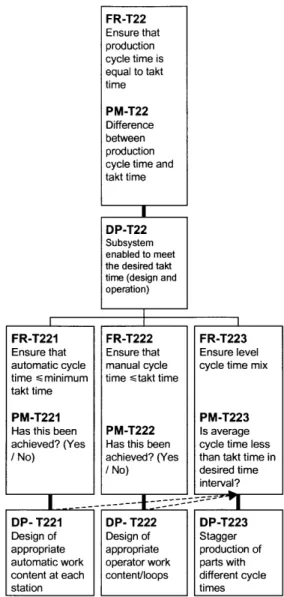
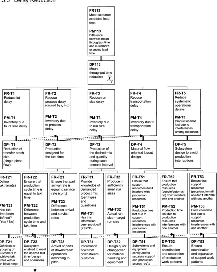
Figure 2.13: Delay Reduction Section of the MSDD (Level III through Level V)... 47
Figure 2.14: Balanced Production [Linck and Cochran, 1999] ... 48
Figure 2.15: Level Production [Linck and Cochran, 1999]... 49
Figure 2.16: Delay Reduction Section of the MSDD (Level V and Level VI) ... 50
Figure 2.17: Level by Cycle Time [Linck and Cochran, 1999]... 51
Figure 2.18: Direct Labor Section of the MSDD (Level III through Level V) ... 53
Figure 2.19: Indirect Labor Section of the MSDD (Level III and Level IV) ... 55
Figure 4.1: Top Levels of the AM SDD ... 90
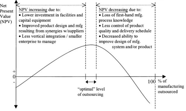
Figure 4.2: Hypothetical NPV Analysis of Decision to Outsource Manufacturing ... 94
Figure 4.3: Cash Flow Diagram for Proposed Product... 95
Development of an Aerospace Manufacturing System Design Decomposition
Figure 4.5: Decomposition of FR/DP- 1 in the AMSDD ... 97
Figure 4.6: Continuous Improvement Section of the AMSDD ... 98
Figure 4.7: Product Design Section of the AM SDD... 100
Figure 4.8: Product Design Section of the AMSDD (Design Stable Processes)... 105
Figure 4.9: Product Design Section of the AMSDD (Affordable Processes)... 106
Figure 4.10: Quality Section of the AM SDD ... 108
Figure 4.11: Quality Section of the AMSDD (Operator Assignable Causes) ... 109
Figure 4.12: Decomposition of FR-114 and DP-114... 111
Figure 4.13: Identifying and Resolving Problems Section of the AMSDD ... 112
Figure 4.14: Predictable Output Section of the AMSDD ... 115
Figure 4.15: Delay Reduction Section of the AMSDD ... 118
Figure 4.16: Delay Reduction Section of the AMSDD (Cycle Time Equals Takt Time) ... 120
Figure 4.17: A M SD D D efinitions... 121
Figure 4.18: Cost Reduction Section of the AM SDD... 122
Figure 4.19: Investm ent Section of the AM SDD ... 126
Figure 5.1: Military Aircraft Manufacturing System Design Decomposition [Wang, 1999].... 132
Figure 5.2: Top Levels of the Military Manufacturing System Design Decomposition and the A M S D D ... 13 5 Figure 5.3: Decomposition of FR/DPm1 1 and FR/DP-1 1... 136
Figure 5.4: Decomposition of FR/DPm12 and FR/DP-12... 138
Figure 5.5: Investment in the Military Decomposition and the AMSDD... 141
Figure 5.6: Hypothetical NPV Analysis of Government Funding... 144
Figure 5.7: M apping of Evaluation FRs to AM SDD ... 146
Figure 5.8: Aerospace Manufacturing System Design Evaluation Tool (1 of 3) ... 149
Figure 5.9: Aerospace Manufacturing System Design Evaluation Tool (2 of 3) ... 150
Figure 5.11: Qualitative Evaluation Method ... 152
Figure 5.12: Evaluation FRs and Performance Metrics... 153
Figure 5.13: Overall Manufacturing System Evaluation ... 154
List of Tables
Table 5-1: A verage Evaluation Tool Scores... 154
Table 5-2: Average Evaluation Tool Scores by Category ... 156
Table 6-1: Net Present Value of Decision to Sell Equipment ... 198
Chapter 1
Introduction
1.1 Motivation
This thesis addresses the need for companies in the aerospace industry to develop new manufacturing systems from a high-level systems perspective. Traditionally, the aerospace industry has been driven by high product performance requirements. This history has resulted in a strong product focus and subjugated many production issues to product concerns. For
example, continuous design upgrades and changes may result in a product having the most modern capabilities available, but makes manufacturing very difficult. This thesis attempts to illustrate the attributes of a manufacturing system design that considers the product-oriented nature of the aerospace industry while addressing production issues from a high-level systems perspective.
The research program undertaken for this thesis was developed as a collaborative effort between the Lean Aerospace Initiative (LAI), and the Production System Design (PSD) Laboratory, both at MIT. The LAI has focused its research on identifying best practices from "lean"
manufacturing that are applicable to the aerospace industry, as well as potential barriers to implementation. [Wang, 1999] The PSD Laboratory has pursued approaches to manufacturing system design based upon an Axiomatic Design methodology. [Suh, 1990; Cochran, 1994; Cochran and Dobbs, 2000b] A prior research effort to apply Axiomatic Design to the aerospace industry by the LAI and PSD Laboratory was presented in Andrew Wang's Master's Thesis
[1999] on the Design and Analysis ofProduction Systems in Aircraft Assembly. In his thesis,
Wang used an Axiomatic Design approach to develop a manufacturing system design
decomposition' that describes the current design of military aircraft production systems. This research identified several barriers to implementing "lean" manufacturing practices and
1 In this thesis, the term decomposition refers to a process in which objectives are broken down into sub-objectives. Satisfying all of a series of sub-objectives will ensure that the original objective is satisfied. The decomposition process can be iterated as many times as necessary until objectives and sub-objectives can be easily understood by the designer. In Axiomatic Design, decomposition refers to defining the Functional Requirements (FRs), i.e.
Development of an Aerospace Manufacturing System Design Decomposition
contrasted the military manufacturing system against a Manufacturing System Design Decomposition (MSDD) approach.
1.2 The Manufacturing System Design Decomposition
The Manufacturing System Design Decomposition (MSDD), originally called the Production System Design Decomposition, was developed by the Production System Design Laboratory. [Carrus and Cochran, 1998; Suh et al, 1998; Cochran, 1999] The purpose of the MSDD is to "clarify the objectives, to design solutions, and to assist industry in developing better"
manufacturing systems. [Cochran and Dobbs, 2000b, p. 359] The Manufacturing System Design Decomposition is the result of following an Axiomatic Design methodology. [Suh, 1990] The MSDD decomposes the top-level goal of a company into lower-level requirements and design
solutions. This decomposition process results in a generalized manufacturing system design. The general manufacturing system design relationships represented by the MSDD are intended to apply to repetitive, discrete part manufacturing systems in a broad range of industries, rather than to a specific manufacturing system. The MSDD represents relationships that exist in any
manufacturing system. These relationships affect production quality, throughput time, cost, and production investment.
It is hoped that the thinking represented by the MSDD will be used as an approach to help guide the design and development of many different types of repetitive, discrete part manufacturing systems. The MSDD should not be seen as an implementation methodology that can be followed step-by-step when designing a new manufacturing system. Designers should use the MSDD as a lens through which the overall manufacturing system design is observed. If an existing
manufacturing system design does not closely correspond to the MSDD, comparison with the
MSDD can help to identify solutions that will allow the system to better meet the objectives
represented by the MSDD.
Although it was largely based upon research in the automotive industry, the MSDD was intended to apply to a broad range of industries repetitively producing discrete products. [Cochran, 1999] (As opposed to continuous manufacturing processes, such as oil refining, steel processing, etc.) When the MSDD was presented to the aerospace industry, many people expressed great interest in the MSDD and its implications for the industry. [Lean Aerospace Initiative, 1998b] The
MSDD was received as a possible new tool that could be used for developing future aerospace
manufacturing systems. The MSDD was also viewed as a tool that could be used to understand the impact of military procurement policies on the design of aerospace manufacturing systems. The edict from the military leadership was to describe the activities and policies within the military that cause military contractors to not be "lean." [Lean Aerospace Initiative, 1998a] While members of the aerospace industry believed that the MSDD approach was a valuable one, there was concern that a model based on design relationships apropos to the automotive industry and the consumer product manufacturing industry could not be applied to aerospace
manufacturing. The research upon which this thesis is based is in response to the above concerns.
This thesis seeks to answer the above questions. To answer these questions, an Aerospace Manufacturing System Design Decomposition (AMSDD) is developed. The hypothesis is that the resulting AMSDD will be very similar to the original MSDD. This hypothesis assumes that the design relationships illustrated by the MSDD apply to a wide range of repetitive, discrete
product manufacturing systems - including the aerospace industry. If the AMSDD and MSDD
are very similar, this hypothesis will be proven.
After developing the AMSDD, this thesis revisits Andrew Wang's work to see how the AMSDD compares with the "as-is" decomposition developed by Wang [1999]. In addition, an Aerospace Manufacturing System Design Evaluation Tool is developed as a potential means for evaluating current manufacturing system designs and evaluating areas that need improvement. It is further proposed that this Evaluation Tool could be used to identify the impact of procurement policies on manufacturing system designs. By comparing evaluations of multiple military aerospace manufacturing systems, it may be possible to discern trends that result from military procurement policies.
1.3 Approach for Developing the Aerospace Manufacturing System Design Decomposition
The AMSDD was developed through extensive research at many aerospace manufacturing companies. The MSDD was used as the basis for the research and provided a framework for data collection. Over fifty structured interviews took place at aerospace manufacturing facilities
Development of an Aerospace Manufacturing System Design Decomposition
producing products that included military and commercial aircraft, space launch vehicles, satellites, and electronic systems. In order to capture multiple perspectives, interviewees included multiple engineers and managers from each organization that was visited.
The interviews first familiarized participants with Axiomatic Design and the motivation for developing a manufacturing system design decomposition. Interviewees were then taken step-by-step through a detailed explanation of the MSDD. The participants were asked to suggest changes that would enable the MSDD to better illustrate the manufacturing system requirements present at each site. After collecting the data, the manufacturing system requirements and means that were found to be missing from the MSDD were integrated into the new AMSDD.
1.4 Chapter Overviews
Chapter 2 explains the motivation for developing the Manufacturing System Design
Decomposition and describes the Axiomatic Design process used to develop the MSDD. A detailed description of the entire MSDD is presented to familiarize readers with the assumptions underlying the MSDD and to clarify the intentions of each Functional Requirement (FR) and Design Parameter (DP) selected.
Chapter 3 presents a compilation of the feedback obtained from industry members regarding the applicability of the MSDD to the aerospace industry. The feedback highlights concerns that are unique to the aerospace industry, describes which suggestions for improvements have been added to the AMSDD, and explains why.
Chapter 4 develops the new Aerospace Manufacturing System Design Decomposition while considering the issues presented in Chapter 3. The chapter focuses upon the FRs and DPs that have changed from the original MSDD.
Chapter 5 compares the AMSDD to the Military Manufacturing System Design Decomposition,
developed by Wang [1999], to illustrate opportunities to improve military procurement policies. The chapter then presents the Aerospace Manufacturing System Design Evaluation Tool (Eval Tool) and explains how the Eval Tool can be used. The Eval Tool is used to evaluate the manufacturing system designs of three plants visited during development of the AMSDD.
strengths and weaknesses of manufacturing systems. This analysis is then used to develop
possible links between the evaluated manufacturing system designs and government procurement policies.
Chapter 2
The Manufacturing
System Design
Decomposition
2.1 Introduction
Designing a manufacturing system to achieve a set of strategic objectives involves making a series of decisions over time [Hayes and Wheelwright, 1979]. Manufacturing systems contain many variables with initially unknown interdependencies. Making design decisions in a way that supports a firm's high-level objectives requires an understanding of how detailed design issues affect the interactions among various components of a manufacturing system. [Cochran et al, 2000] These interactions must be made visible and understood by designers to help them develop a successful system implementation strategy. Successful implementation requires that designers understand that the manufacturing system consists of more than a series of processes designed to fabricate and assemble a product. The complete manufacturing system consists of the "arrangement and operation of machines, tools, material, people and information to produce a value-added physical, informational or service product whose success and cost is characterized
by measurable parameters." [Cochran and Dobbs, 2000a] Cochran et al [2000] define the
process of manufacturing system design as:
All aspects of creating and operating a manufacturing system. Creating the system includes
equipment selection, physical arrangement of equipment, work design (manual and
automatic), standardization, design of material and information flow etc. The result of the creating process is the factory as it looks in a snapshot of time. Operation includes all aspects that are necessary to run the created factory.
Problems often occur when companies try to implement tools from one manufacturing system design or partial solutions without first understanding how the solutions fit into a complete manufacturing system design. Many companies have tried unsuccessfully to implement aspects of the Toyota Production System (TPS) because they have confused the tools and practices of
TPS with the system itself. [Spear and Bowen, 1999] For example, implementing a kanban
Development of an Aerospace Manufacturing System Design Decomposition
[1989] describes kanban as a means for putting TPS into practice, but stresses that development
of a kanban system flows naturally from the thinking implicit in TPS.
The Manufacturing System Design Decomposition, referred to in this thesis as the MSDD, provides a systematic method of identifying business objectives (Functional Requirements) and the means (Design Parameters) to achieve those objectives. [Cochran, 1999] The MSDD is intended for use as a conceptual tool that guides the thinking of manufacturing system designers, rather than as a step-by-step design methodology. The MSDD illustrates relationships that exist in every manufacturing system and affect production quality, throughput time, cost, and capital investment. The MSDD can be used to help designers understand how the decisions that they make impact a manufacturing system's ability to meet high-level business objectives. For this reason, the functional requirements (objectives) and design parameters (means) presented by the
MSDD are generalized in order to apply to a wide range of manufacturing systems. [Kuest, 1999]
2.2 Axiomatic Design
The Manufacturing System Design Decomposition was developed by applying an Axiomatic Design methodology. Axiomatic Design defines design as the "creation of synthesized solutions in the form of products, processes, or systems that satisfy perceived needs through mapping" between Functional Requirements (FRs) and Design Parameters (DPs). [Suh, 1990] The two design axioms are the Independence Axiom and the Information Axiom. The Independence Axiom states that a good design must maintain the independence of thefunctional requirements. The Information Axiom requires minimizing the information content of the design. To
accomplish independence of the Functional Requirements requires determining a physical design implementation (or solution), called a Design Parameter (DP), that affects only one Functional Requirement (FR). Independence also means that the definition and selection of the FRs must be independent.
Zigzagging
The first step in Axiomatic Design of manufacturing systems is defining the top level FRs for the manufacturing system being designed. Next, specific Design Parameters must be determined. This process is called zigzagging. The "zig" in zigzagging means translating Functional
Requirements to Design Parameters at the same level in the design hierarchy. If axiom 1 is observed, the definition of the FRs for the next level of the design decomposition can begin. "Zag" means going from the Design Parameters of a parent level to the Functional Requirements of the next level. It is not possible to decompose the functional hierarchy unless the FRs of the next level satisfy the context of the parent DP level. Figure 2.1 illustrates the process of zigzagging. It should be noted that this process is not linear and may require several iterations.
What?
How!
FR11l FR12 |FR111| |F12 FR121| R12 FRI122 ZIG 1. Define FR(s) 2. Define DP(s)3. Define Design Matrix, FR = [DM]*DP
to determine degree of coupling
P1
DP12
ZAG
Define the FR's of the next lower level
Figure 2.1 Zigzagging [Linck, 1996]
Design Matrices
To determine whether the first Axiom has been achieved, and whether decomposition to the next lower level can proceed, the relationship between the FRs and DPs must be expressed in terms of a design matrix. The design that constitutes the FR-DP relationships may be of three types: uncoupled, partially coupled, and coupled. Figure 2.2 illustrates the three types of design matrices. Further decomposition is not possible until the design relationship is shown to be uncoupled or partially coupled.
Development of an Aerospace Manufacturing System Design Decomposition
uncoupled
partially coupled
coupled
Design FRI =[X
O
DPI FRI =[X o DP FR1 =[X X] DPIEquation FR2J 0 X DP2J FR2 _X X_ DP2 FR2 X X_ DP2
FR2(A) FR2(A)- FR2(A)
Graphical
Representation FR2(A)- FR2(A)- -
FR2(A)-FR1(A) FR1(B) FR1(A) FR1(B) FR1(A) FR1(B)
Figure 2.2: Design Matrices [Cochran, 1994; Wang, 1999]
An uncoupled design is represented by a diagonal matrix. X's represent the relationships between the FRs and DPs. An uncoupled design ensures that the chosen DPs independently impact the FRs. When implementing an uncoupled design, the DPs may be performed in any order. [Suh et al, 1998]
In a partially coupled design, one or more FRs are affected by more than one DP. A partially coupled design is represented by an upper or lower triangular matrix. A partially coupled design is path dependent. This dependency means that the order of DP implementation is critical. For example, when implementing a partially coupled design, the DPs should be implemented so that the DP that affects the most FRs is implemented first. In the partially coupled matrix, the order of DP implementation is DPI then DP2. Independence is achieved by virtue of the
implementation path.
A coupled design matrix does not maintain independence of the FRs.
Although Axiomatic Design indicates that in a partially coupled design DPs that affect the most FRs should be implemented first, this is not always possible. For example, in the top levels of the MSDD, shown in Figure 2.4, the relationship between FR 11, FR12, FR13, and DP 11, DP12, and DP 13 is a partially coupled design. This partial coupling indicates that the order of
implementation should be DP 11, DP12, then DP13. In reality, it would not be possible to implement the DPs in this order, because one could not begin DP 11, "Production to maximize customer satisfaction," before making an investment in the manufacturing system, DP 13. Therefore, in manufacturing system design, the coupling indicates which DPs should be considered first. In the case of FR/DP II through FR/DP 13, a manufacturing system designer
would first consider how to maximize customer satisfaction, then how to eliminate non-value adding sources of cost, and finally how to minimize long-term investment.
2.3 The Manufacturing System Design Decomposition
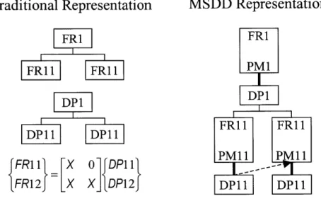
The MSDD uses a graphical representation of coupling between DPs and FRs, which varies slightly from the traditional Axiomatic Design representation, which uses design matrices. Figure 2.3 illustrates the traditional representation of an FR/DP pair and its decomposition into sub-FR/DPs.
Traditional Representation MSDD Representation
FRI FRl FRil FRll PM1 DP1 FRIl FRIl DPll DPll FFR1l1 [X 0 DPll PMl -PMll FR12J LX X_ DPI2J DPl DPll
Figure 2.3: Traditional and MSDD Representation of FRs and DPs
The traditional representation separates the FRs and the DPs into two separate structures and requires that design matrices be shown to illustrate the coupling between FRs and DPs. The
MSDD representation groups each FR with the DP that satisfies it, connecting them with a dark
line. Coupling is illustrated by a dashed arrow from a DP to an FR. The MSDD also includes performance measurements (PMs) that can be used to evaluate whether each FR has been achieved. Including PMs helps to make the MSDD a useful tool for guiding manufacturing system design, because the decomposition illustrates the manufacturing system objectives (FRs), the means of achieving the objectives (DPs), and a way to measure how well the objectives have been achieved (PMs).
Development of an Aerospace Manufacturing System Design Decomposition
The layout of the MSDD is arranged so that the DPs that affect the most FRs are on the left-hand side. This arrangement helps designers to understand which DPs, as a result of coupling, have the greatest impact on the FRs of the overall manufacturing system design as well as the FRs within a section of the MSDD. The arrangement is not meant to imply that FRs and DPs towards the right-hand side of the MSDD are less important than FRs and DPs on the left.
The MSDD presented in this thesis is MSDD version 5.1. A full decomposition of version 5.1 can be found in Appendix A. The Aerospace Manufacturing System Design Decomposition is based on MSDD v.5.1, but uses data collected from interviews using MSDD version 5.0. The
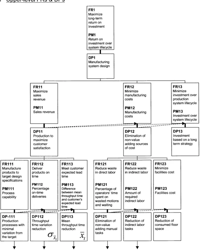
2.3.1 Upper-level FRs & DPs FRI Maximize long-term return on Investment PM1 Return on investment over system lifecycle DPI Manufacturing system design FR1 1 FR12 FRI13
Maximize Minimize Minimize
sales manufacturing investment over
revenue costs production
system lifecycle
PM11I PM12
Sales revenue Manufacturing PM13
costs Investment over system lifecycle ---
---DP11 DP12 DP13
Production to Elimination of Investment
maximize non-value based on a long
customer adding sources term strategy
satisfaction of cost
FRI11 FRI12 FRI13
Manufacture Deliver Meet customer
products to products on expected lead
target design time time
specifications
PM112 PM113 PM111 Percentage Difference
Process on-time between mean
capability deliveries throughput time
and customer's expected lead time
DP-111 DPI12 DP1I13
Production Throughput Mean
processes with time variation throughput time
minimal reduction reduction
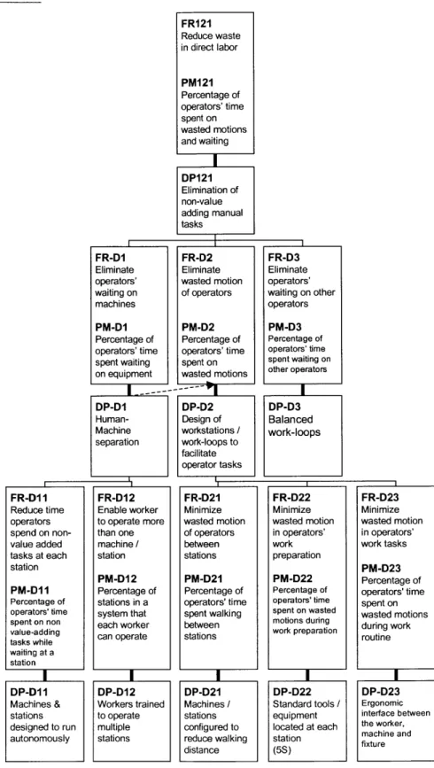
variation from the target t FRI21 Reduce waste in direct labor PM121 Percentage of operators' time spent on wasted motions and waiting DP121 Elimination of non-value adding manual tasks FR122 Reduce waste in indirect labor PM122 FR123 Minimize facilities cost PM123 F iliti t Amount 0 ac us cos required indirect labor DP122 DP123 Reduction of Reduction of
indirect labor consumed floor
tasks space
Figure 2.4: Top Three Levels of the MSDD (version 5.1)
The top-level functional requirement of the MSDD, FRI, is to "Maximize long-term Return on Investment." The phrase long-term indicates that short-term solutions that result in an artificially high return on investment (ROI) should not be selected. Drastically slashing investment for one
Development of an Aerospace Manufacturing System Design Decomposition
quarter may temporarily make a company look like it has a high ROI, but the harmful effects of this decision will reduce the company's long-term ROI. Therefore, the top-level design
parameter, DPI, is "Manufacturing system design." The selection of DPI indicates that in order to maximize long-term ROI, it is important to design a manufacturing system, not let it evolve haphazardly over time. The performance measurement that indicates how well FRI has been achieved is PM1, "Return on investment over system lifecycle." It should be noted that the
MSDD addresses maximizing the long-term ROI of a company's manufacturing system. The
ROI of product design, sales and marketing, and other functions within a company are not considered by this version of the MSDD.
The second level FRs were derived from the formula for ROI [Suh, et al, 1998]:
ROI = Sales -Cost Investment
In order to maximize ROI, a company must fulfill FRI 1, "Maximize sales revenue," FR12, "Minimize manufacturing costs," and FR13, "Minimize investment over production system lifecycle." DP 11, "Production to maximize customer satisfaction," indicates that, within a manufacturing system, the only way to increase sales revenue is to produce products that satisfy the customers. Other methods of increasing sales revenue, such as product design and marketing decisions are external to the manufacturing system and not addressed by the MSDD. DP12, "Elimination of non-value adding sources of cost," indicates that companies should eliminate any activities in the manufacturing system that do not add value to the final product. DP13, "Investment based on a long term strategy," specifies that companies should make investment decisions that will achieve the company's long-term objectives. These investment decisions may not appear to be the best choices if they are evaluated over a short period, but evaluating them over a long period should indicate that these decisions require the least investment for achieving a set of goals. The decomposition of FR/DPI is a partially coupled design. DPi1 affects FRI 1, FR12, FR13, and DP12 affects FR12 and FR13. This coupling indicates that production to maximize customer satisfaction affects a company's ability to minimize production costs and to minimize long-term investment. The coupling also indicates that eliminating non-value adding costs affects a company's ability to minimize its long-term investment requirements.
FR/DP 1 are decomposed into three sub-FRs, FRI 11, FRI 12, and FRI 13. FRIll requires a company to "Manufacture products to target design specifications" and is satisfied by DP 111, "Production processes with minimal variation from the target." FRI 12, "Deliver products on time," is satisfied by DP 112, "Throughput time variation reduction." And FRI 13, "Meet customer expected lead time," is satisfied by DP 113, "Mean throughput time reduction." These FRs and DPs indicate that the best way to maximize sales revenue by maximizing customer satisfaction is to produce high quality products in a reliable, short amount of time.
FR/DP12 is decomposed into FR121, FR122, and FR123. FR121, "reduce waste in direct labor," is satisfied by DP121, "Elimination of non-value adding manual tasks." This FR/DP pair indicates that manual labor is important to the manufacturing system and that workers should not be required to perform tasks that do not add value to the final product. FR122, "Reduce waste in indirect labor," is satisfied by DP122, "Reduction of indirect labor." The requirement to reduce indirect labor recognizes that the number of supervisory and management positions in a
manufacturing system should be kept as low as possible, because these jobs do not directly add value to products. FR123, "Minimize facilities cost," is satisfied by DP123, "Reduction of
consumed floor space." This FR/DP pair assumes that costs associated with facilities (electricity, heating, maintenance) should be kept as low as possible by efficiently utilizing facilities.
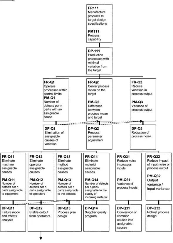
Development of an Aerospace Manufacturing System Design Decomposition 2.3.2 Quality FR111 Manufacture products to target design specifications PM111 Process capability DP- 11 Production processes with minimal variation from the target FR-Q1 FR-Q2
Operate Center process
processes within mean on the
control limits target
PM-Q1
Number of PM-Q2
defects per n Difference
parts with an between
assignable process mean
cause and target
DP-Q1 DP-Q2 Elimination of Process assignable parameter causes of adjustment variation FR-Q3 Reduce variation in process output PM-Q3 Variance of process output DP-Q3 Reduction of process noise FR-Q1 I Eliminate machine assignable causes PM-Q11I Number of defects per n parts assignable to equipment FR-Q12 Eliminate operator assignable causes PM-Q12 Number of defects per n parts assignable to operators FR-Q13 Eliminate method assignable causes PM-Q13 Number of defects per n parts assignable to the process I --- -' --- 4--- -- q DP-Q11 DP-Q12 DP-Q13
Failure mode Stable output Process plan
and effects from operators design
analysis
Figure 2.5: Quality Section of the MSDD (Level III through Level V)
FR/DP1I1I1 is decomposed into FR-Q 1, FR-Q2, and FR-Q3. These three FRs indicate how companies can improve the quality output of their manufacturing systems. The concepts that are
FR-Q14 Eliminate material assignable causes PM-Q14 Number of defects per n parts assignable to the quality of incoming material DP-Q14 Supplier quality program FR-Q31 Reduce noise in process inputs PM-Q31 Variance of process inputs DP-Q31 Conversion of common causes into assignable causes FR-Q32 Reduce impact of input noise on process output PM-Q32 Output variance/ input variance DP-Q32 Robust process design
decomposed are based upon statistical process control (SPC) methods. [Chu, 2000; Montgomery,
1985] FR-Q1, "Operate processes within control limits," is satisfied by DP-Q1, "Elimination of
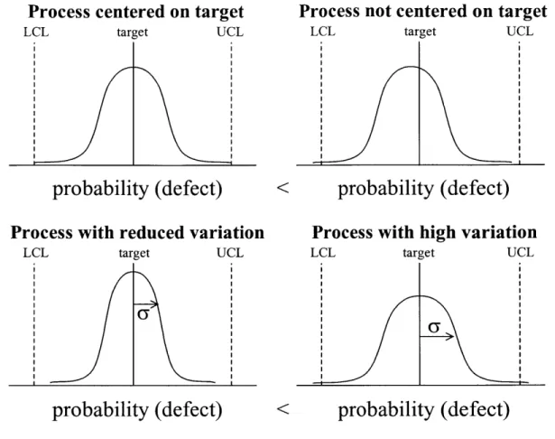
assignable causes of variation." Assignable causes of variation are causes that can be identified. These causes should be traced down and eliminated in order keep processes within specified control limits. FR-Q2, "Center process mean on the target," is satisfied by DP-Q2, "Process parameter adjustment." If a process mean is not centered on the target, the probability that a defect will be created increases, as shown in Figure 2.6. Design of experiments helps guide the adjustment of process parameters to center the mean on the target. FR-Q3, "Reduce variation in process output," is satisfied by DP-Q3, "Reduction of process noise." Reducing the variation of a process output also decreases the probability that a defect will be created, as shown in Figure
2.6. Process noise reduction involves reducing the types of variation that a process receives as
input as well as reducing the effect that input noise has on the output. Noise can be
environmental, such as temperature, humidity and vibration, or noise can be variation in the quality of incoming materials and parts.
Development of an Aerospace Manufacturing System Design Decomposition
Process
LCLcente
targred on target
et UCLprobability (defect)
Process with reduced variation
LCL target UCL
probability (defect)
Process not centered on target
LCL target UCL
<
probability (defect)
Process with high variation
LCL target UCL
< b G
<
probability (defect)
Figure 2.6: Effects of Centering and Reducing Variability of Manufacturing Processes
FR/DP-Q3 is decomposed into FR-Q31 and FR-Q32 in order to better illustrate how process variation can be reduced. FR-Q3 1, "Reduce noise in process inputs," is satisfied by DP-Q3 1, "Conversion of common causes into assignable causes." Once common causes of process noise have been converted into assignable causes, the causes can be eliminated using the methods
decomposed from FR-Q1. FR-Q32, "Reduce impact of input noise on process output," is satisfied by DP-Q32, "Robust process design." Identifying and eliminating input noise is one way to reduce process variation, but it may never be possible to identify and eliminate all sources of noise. Making a process robust to input noise helps to ensure that processes are not disrupted
Material
N
easurement Machine Method Cause Factors Process Characteristics 2.1Figure 2.7: Ishikawa Fishbone Diagram [Ishikawa, 1985]
FR/DP-Q1 is decomposed into FR-Q 11, FR-Q 12, FR-Q 13, and FR-Q 14. This decomposition follows four of the branches of an Ishikawa fishbone diagram, such as the one shown in Figure
2.7. FR-Q1 1, "Eliminate machine assignable causes," is satisfied by DP-Q1 1, "Failure mode and
effects analysis." By analyzing the failure modes and effects of machines, the machines can be redesigned or modified to prevent making bad parts. FR-Q12, "Eliminate operator assignable causes," is satisfied by DP-Q12, "Stable output from operators." Obtaining consistently high-quality output from workers is very important. Further decomposition of FR/DP-Q12 is shown in Figure 2.8.
FR-Q13, "Eliminate method assignable causes," is satisfied by DP-Q13, "Process plan design."
The way that a process is planned can have a significant impact on quality. It may be much easier to perform some processes early in the fabrication or assembly stages of a product. For example, machining parts prior to a hardening process may significantly reduce machining costs.
If the machined surfaces require tight tolerances, however, machining prior to heat treatment
may not be a good choice due to distortion of the part during the heat treatment process.
FR-Q14, "Eliminate material assignable causes," is satisfied by DP-Q 14, "Supplier quality
-* Effect
(Quality characteristics)
Man
\I
Development of an Aerospace Manufacturing System Design Decomposition
program." Incoming product quality has a direct impact on the output quality of a manufacturing system. It is not possible to produce good products if suppliers cannot reliably provide high-quality materials and components.
FR-Q12 Eliminate operator assignable causes PM-Q12 Number of defects per n parts assignable to operators DP-Q12 Stable output from operators FR-Q121 FR-Q122 FR-Q12
Ensure that Ensure that Ensure t operator has operator operator
knowledge of consistently errors do required tasks performs tasks translate
correctly defects
PM-Q121
Number of PM-Q122 PM-lQ1
defects per n Number of Number o parts caused by defects per n defects p an operators lack parts caused by parts cau of understanding non-standard human er about methods methods
DP-Q121 DP-Q122 DP-Q1;
Training Standard work Mistake program methods operatio (Poka-Y 3 hat human not to 23 f er n sed by ror 23 proof ns oke)
Figure 2.8: Quality Section of the MSDD (Level V and Level VI)
FR-Q12 is further decomposed into FR-Q121, FR-Q122, and FR-Q123. FR-Q121, "Ensure that operator has knowledge of required tasks," is satisfied by DP-Q121, "Training program." A training program is necessary to ensure that operators have more than just a working knowledge of their tasks. FR-Q122, "Ensure that operator consistently performs tasks correctly," is satisfied
by DP-Q122, "Standard work methods." It is important that tasks are performed identically from
one worker to the next. A lack of standardization increases the likelihood that workers will make mistakes. The ability of a company to standardize work is affected by the quality of its training program. This dependency is illustrated by the coupling between DP-Q121 and Q 122.
FR-Q123, "Ensure that operator human errors do not translate to defects," is satisfied by DP-FR-Q123,
"Mistake proof operations (Poka-Yoke)." Even with a good training program and standard work, mistakes may happen. Equipment should be designed to help operators by preventing them from making mistakes in the first place. Mistake proofing devices include fixtures that only allow a part to be inserted in the proper orientation and machines that will not start if they detect any irregularities in the product. [Monden, 1998; Ohno, 1988] Figure 2.9 shows an example of an operation before and after mistake-proofing. Without the mistake-proofing device, a part could be inserted into the fixture incorrectly. After mistake proofing, the part can only be inserted one way.
Before Improvement:
-Part could accidentally be loaded into fixture in reverse orientation. Correct:
After Improvement:
-A small feature was added
to the fixture to prevent incorrect loading.
Incorrect:
Development of an Aerospace Manufacturing System Design Decomposition
2.3.3 Identifying and Resolving Problems
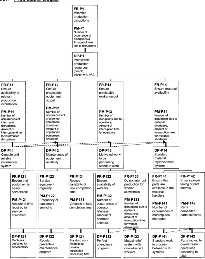
FR112 Deliver products on time PM112 Percentage on-time deliveries DPI12 Throughput time variation reduction (_ Xt FR-RI FR-PI Respond Minimize rapidly to production production disruptions disruptions PM-RI PM-PI
Time between Number of
occurrence and occurrence of
resolution of disruptions &
disruptions Amount of timelost to disruptions
--- ~-+
DP-RI DP-P1
Procedure for Predictable
detection & production
response to resources
production (people,
disruptions equipment, info)
Figure 2.10: Decomposition of FR112 and DP112 (Level III and Level IV) FR/DP 112 is decomposed into two FRs, FR-RI and FR-P 1. FR-R1, "Respond rapidly to production disruptions," is satisfied by DP-R1, "Procedure for detection & response to
production disruptions." The section of the MSDD that is decomposed from FR/DP-R1 is called
Identifying and Resolving Problems. FR-P1, "Minimize production disruptions," is satisfied by
DP-Pl, "Predictable production resources (people, equipment, info)." The section of the MSDD that is decomposed from FR/DP-P1 is called Predictable Output.
![Figure 2.14: Balanced Production [Linck and Cochran, 1999]](https://thumb-eu.123doks.com/thumbv2/123doknet/14733135.573502/48.918.283.667.521.771/figure-balanced-production-linck-cochran.webp)