DESIGN STUDY FOR A 15 BEV ACCELERATOR BUILDING
FOR
THE CAMBRIDGE DESIGN STUDY GROUP
Submitted in Partial Fulfillment of
the Requirements for the Degree of
Master of Architecture
To:
School of Architecture and Planning
Massachusetts Institute of Technology
August 24, 1953
A
By: - - - -
L
-Peter Leal Floyd
Mu
fLibaries
Document Services
Room 14-0551 77 Massachusetts Avenue Cambridge, MA 02139 Ph: 617.253.2800 Email: [email protected] http://libraries.mit.edu/docsDISCLAIMER OF QUALITY
Due to the condition of the original material, there are unavoidable
flaws in this reproduction. We have made every effort possible to
provide you with the best copy available. If you are dissatisfied with
this product and find it unusable, please contact Document Services as
soon as possible.
Thank you.
Some pages in the original document contain text that
runs off the edge of the page.
216 Beacon Street
Boston
Massachusetts
August 24, 1953
Pietro Belluschi
Dean of Architecture
Massachusetts Institute of Technology
Cambridge, Massachusetts
Dear Dean Belluschi:
In partial fulfillment of the requirements for the degree of Master of
Architecture, we submit our thesis, "Design Study for a 15 Bev Accelerator
Building."
Very truly yours,
Peter Leal Floyd
ABSTRACT
DESIGN STUDY FOR A 15 BEV ACCELERATOR BUILDING
By Peter Leal Floyd and John Insco Williams
Submitted for Degree
of
Master
of
Architecture,
School of Architecture and Planning,
Massachusetts Institute of Technology,
August 24, 1953
The problem presented to us by the Cambridge Design Study Group in
March 1953 was to help formulate a program and propose solutions for the
design of a structure to house a 15 Bev particle accelerator and associated
research and service facilities.
The proposed accelerator would be the
largest and most.powerful "atom smasher" in the world, being
7-
times more
powerful than the Cosmotron at Brookhaven National Laboratory, presently
the world's largest accelerator.
Actually this new machine would only be
a pilot model for future development of larger, more powerful accelerators.
Designs have been suggested for a site at Harvard University and an open
TABLE
OF
CONTENTS
INTRODUCTION
"A 100 BEV ACCELERATOR"
-
A DISCUSSION
OF ACCELERATOR DEVELOPMENT FROM "SCIENTIFIC
AMERICAN" MAGAZINE
"DESIGN STUDY FOR A 15 BEV ACCELERATOR BUILDING"
BY THE CAMBRIDGE DESIGN STUDY GROUP
THE DESIGN OF A 15 BEV ACCELERATOR LABORATORY
ON AN OPEN SITE
INTRODUCTION
This design project was undertaken by
us
in March 1953, at the request
of
Mr.
Stanley Livingston, Director of the Cambridge Design Study Group,
which was in the process of designing a high-energy particle accelerator
under contract with the Atomic Energy Commission.
Our study was carried
out in two phases:
the first included development of the program, and
design of a laboratory facility located at the area about the existing
Harvard Cyclotron on the Harvard University campus; and this work was carried
out through the month of June 1953;
the second phase included the restatement
of the program and a solution to fit an open site in the country, near Boston.
Work on the first phase included numerous conferences with Professor Livingston
and other members of the Cambridge Design Study Group.
A firm of professional
architects was called in to make a detailed study of the minimum facility
while we prepared a somewhat more ideal study, both on the same general location.
A photostatic reproduction of portions of the "Design Study For A 15 Bev
Accelerator" covering a description of the project and of our work on the study
forms the major portion of this written report.
This is followed by a
description of the second phase of the study describing the design of the
laboratory on another site, particularly the important differences between
the solutions on the two locations.
As practically no reference material is
available on this subject our research was carried out through conferences,
interviews, and visits to other accelerator installations.
The authors have
inspected the Cosmotron at Brookhaven National Laboratory, the Harvard
Cyclotron, the M.I.T. Synchrotron, the Cornell Synchrotron and the-Cyclotron
at the University of Rochester.
A reproduction of an article describing
development of accelerators which was published in the May 1953 "Scientific
American" magazine provides a good introduction of the subject to the layman.
eVWtific
A 100
-
BILL
RION
-VO
-r
AC CELERATOR
A
year
ago
subatomic particles
were
for
the
first time
accelerated to energies of more than a billion clectron
volts.
Now
a much more
powerful
machine is in prospect
l.y
lF;rne'tI).
I
otiranit
THE
for the past 25 HISTORY years of atomic in asense
physicsisepitomized hy the rise in eitergy of
the machines built to attack the nuIcleus of the atoin. In 19-30 the most iteretic
accetlerator ixnbarded the niceus'with
IW(M).(MM electron volts. Since then the
energv of the machintes has been
in-creased rouighly by a factor of 10 everv
six
vears
[sec chart on the oppositepang'J]. And each
jiump
iii entergv hasopeined
a new field of exploration into the nucleus.Today the most energetic macinme
we have is the Cosinotron at the
Brook-haven National Laboratory. which
ac-celerates bombarditig particles to
2.3
bil-lion electroi volts ( Bev). The
Univer-sity
of California will sot put iiitooper-atioiI a somewhat larger machine of the
sait'm
type that will retach 6 Bev ["Thebeato."h Lloul Smith:
S(
n:\ Iurie AmI.nIics.Chruirry.
19511. Butl to) retto a higher order of elierg y. a1 iew priln-ciple is iietled. just ats w%-ias requlirtd for
cac jmlilp ill the past. Such a prilnciple
has beeni w\ orked olit in the last It.'. .
moiths by i grouip at Brookhaivien. Tihe
et-sigtI is called the "strolig-focu'lsing
synhrotro. aid with it phy sicists hope
to reach 100 Bev. A matchile of :30 Bev along these lies alreadv is being
de-signed by the uiilders of the new ccitral
uilear research laboratoiy piojected by
a group of European coitiies. Before we discuss the iew idca. let
is review britfly the rtasins for the
scrmitiliblt. to prouie' higher ntetrtgios.
Essentially what we wanit is to) get a hetter bok at the extrecmely tiny\ nuclei
of atomls. To See what solmething- hloks
like \%(
g-enlerally
shinec
lighIt fin it. When
-4-tIi - l jct is smaIL. ut may nted a mi-croiscp. But for atomis III illich i I . n a
m IiCrosop wS()N \ill no( t doI1 . h1
~
C.II it anIIII-wavelengIth of lighllt. An] aO t.i n111ul s
is Imaller than k n \ elt 'Iisibleh ot
liglit Iby at factor 5(i 5( )million. It,
diiI-etcr is oitIy abmt 4)1 triliIitth It a
centimeter. To "see- it we v mut have\ wa-t\eleng'ths of someitthing-_ liketha i/A OnlyI\ the atomic
particleIs
thenmu ho,, cangenera-ite such.I wavelngths.
A
BEANi of palrticle(s. like a ha am oflighlt. has the c rt riic of,
waves. InI accor-danlce uith quaniltumil
herthe waveleng4-th anoewiated w\ith
at given i parlticle decretasecs ws tlat
par-tiele's energyt ( pd ) ineno i.ses. Whenl pr-otonls are- acck rte (I to Iall
enr ofa I w m1illion
eh
Itro m \Ohts-4
J
ACCELERATOR TYPES are -howu iin diagram ab oe.
In linear accelerator itop)
i
hunches of particles cro-seach gap between drift tuibie. jilt when the oscillating
charges on the tules are
such
a- to gise anaccelerat-ing LieL. Cyclotron
t
bottom. left) and n nebro-etclo-troll I Iritrom center I %end particle- repeated4'ol I trotigh
the same gap in larger and larger circles. S nebiro-tron i bottom rightI Leeps particle, on sane circular
path for whole acceleration by changing the
strength
of the magnuet ic field that makes partivles rasel in virile.(Mev),. their wavelength is about a
tril-lionth (10-12) of a centimeter. Thus with
a proton beam of this energy we can
"see" an atomic nucleus. The accelerator
that produces such a beam should really
be called an "atomic microscope" rather
than an atom-smasher.
Now to examine the forces within the
nucleus we need still shorter
wave-lengths, for those forces are exerted over
distances of 10-13 cm. or less. We canobtain a wavelength of 10-13 by
acceler-ating protons to several hundred Mev.
When we bombard the nuclei of atoms
with beams in the energy range of 200
to 450 Mev, we begin to produce mesons
-the particles that are believed to have
something to do with the binding forces
of the nucleus. We know, furthermore,
that other mysterious particles appear
when the nucleus is attacked by the still
shorter wavelengths of the extremely
energetic cosmic rays. To investigate
those particles we need to bombard
nu-clei with billions of electron volts under
controlled conditions in the laboratorv.
The force fields around the proton
operate over distances of 10-14 cm., and
the investigation of these fields also will
require several billion electron volts.
With energies of 10 Bev or more we can
reasonably expect to produce and detect
the so-called negative proton, which so
far is only theoretical. And this is not the
end: the higher we go in energy, the
more questions arise and the more
ener-gy we need to answer them.
So the main problem in designing
ac-celerators is not where we want to stop
but how far we can go. Every successive
design has hit a ceiling beyond which it
could not practicably go. All accelerators
are based primarily on the same
opera-tipn: electric potential (pressure) is
ap-plied to a charged particle and
acceler-ates it across the electric field. The
sim-plest way to accelerate the particle to the
desired energy is to build up the pressure
to the necessary voltage. But this
meth-od, exemplified by the Van de Graaff
electrostatic generator, works only up to
a few million volts; beyond that it
be-comes too difficult to build insulation to
hold the high electric pressure in the
machine.
T
passe by accelerating particles with
HE CYCLOTRON
solved this
im-a series of kicks im-across smim-all electric
fields, instead of in one big field. The
particles travel in a circular path, being
bent into such a path by a magnetic field.
They get their boosts in energy at the
gaps between the D-shaped halves of the
circle
[drawing at left, bottom of
oppo-site page].
Across each gap an electric
field is applied by an alternating current.
so timed in frequency that it applies a
kick to the particles in the direction of
their travel just as they reach each gap
during their revolution. The successive
boosts raise the particles to higher and
MILLIONS OF ELECTRON VOLTS (MEV)
1,000
'1 1925 1930 1935 1940 1945 1950 1955 1960
ACCELERATOR ENERGY shows a steady rise since 1925. DC stands for
direct-current machines; C, for cyclotrons;
B,
for betatrons;
SC,
for
synchro-cyclotrons; PS, for proton synchrotrons such as the Bevatron and Cosmotron.
---Q
-...--...
- -
----
--- --
-
-
---
..
..
---FOCUSING ACTION of alternately converging and diverging lenses, which
combine to give a net converging effect, demonstrates how the magnetic
fields in a strong-focusing system would
hold
atomic particles on a
path.
higher speeds. As their speed increases, they spiral out into larger and larger
cir-eles, so that they still reach the gaps
after the same interval each time, in step with the oscillating field. Hence the pre-scription for stepping up the energy of eyclotrons is simple: build them bigger, so the accelerated particles can spiral out in larger circles. But again this works only up to a point. When the particles reach very high speeds, they begin to in-crease in mass, according to relativity principles, and now they take a longer time for each round trip and fail to reach the gaps in synchronization with the ac-celerating field. The energy limit of a cyclotron, for protons, is about 15 Mev. The answer to the-cyclotron's limita-tions was a change in design that com-pensated for the particles' increase in mass. The oscillator was made variable so that it adjusted its frequency to the in-creasing length of the particles' trip and synchronized its boost with their arrival at the gaps each time. This type of ma-chine is called a synchro-cyclotron. A further refinement was to make the mag-netic field, as well as the frequency of the
electric field, adjustable. Now the path
of the particles can be kept constant: The strength of the magnetic field is in-creased as the particles gain in energy, so that they always travel in the same circle. This type of machine, called the synchrotron, requires less magnet iron than the synichro-cyclotron, because it does not need a magnetic field ever-where inside it but only near the fixed orbit of the particles.
Brookhaven's Cosmotron and Califor-nia's Bevatron are synchrotrons. They have raised the acceleration of particles to the billion-volt range, and in theory there is no limit to the energy they coul(I achieve. But there is a practical limit: the size of the magnet. The Bevatron magnet already weighs 10,(x) tons, and a 30-Bev synchrotron would require at least 100,000 tons of iron.
AFTER
THE COSMOTRON went into operation last summer, a group of physicists at Brookhaven began to speculate on how the magnet size might be reduced to make practicable a much bigger machine than the Cosmotron. Intle Cosiioron( I tIe .particles r ~ l
through i doumghmnutt-staped tuibe. To
reach the billion-volt energy range they,
must go round and round through the tibe for the enormous distance of 150,-(X) miles. The slightest error in aiming the particles when they are shot into the
tiube will take themi off the course long
before they reach their goal. They may
also be knocked off course bv collisions
with stray gas molecules in the evacu-ated tube or by fhituations in the ac-celerating voltage or frequency. The Cosmotron's magnet keeps them in the necessary orbit by means of corrective forces that push the particles back on the course when they begin to stray. Even so. the particles must be given a fairly wide channel to travel in, and that is the main reason the magnets must be so large. In the Cosmotron the pipe through
which the particles move is 7 by 36
inches in cross section, and the magnet is eight feet thick.
Suppose that the straying of the par-ticles could be controlled so closely that they stayed almost exactly on a perfectly circular orbit. Then the channel could be
THE COSMOTRON at Brookhaven National
Labora-tory is the largest accelerator yet built. In it protons
have attained an energy of 2.3 billion electron volts I lev1. In the foreground is heavy concrete shielding.
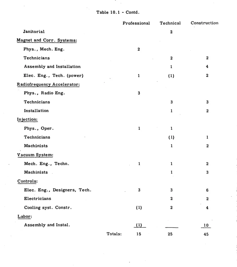
completion is 3 years. However, experience shows that unforeseen problems and additional expenses arise in the development and construction of the first model of a new type of accel-erator, and that such problems also increase the time schedule. We discuss the factors in-volved in estimating a contingency cost figure in Sec. 11.1, concluding that a figure of 30 per
cent in both cost and time is reasonable. So the maximum estimated cost for construction is
$7, 900, 000, and the time for completion 4 years. Estimates of maintenance costs for opera-tion after compleopera-tion include an expected coordinaopera-tion of research activities with existing programs at Harvard and M.I. T., and the collaboration of scientists from other universities
in the New England area. Operating costs are estimated at $ 750, 000/year, and include a
maintenance staff of 32 engineering and technical personnel and support for the research ac-tivities of 30 scientists.
1. 2 Basic Design
The chosen maximum energy of 15 Bev and the estimated peak flux density at the
central orbit of 14 kilogauss require a central orbit radius r0 of 124 ft., following the
relativistic relation:
r [T(T + 2E0)]V2
0.3 B (meters) (1)
where. T is kinetic energy and E the proton rest energy expressed in Bev units and B is flux density in webers /m2 at the orbit. With the number of magnet sectors and length of
straight section chosen, the overall radius of the magnet circle R is 160 ft. and the total
circumference is 1006 ft.
Magnetic field rises with time in a cycle reaching the peak field of 14 kilogauss in about 0. 75 second; it is then reduced to zero in about 0. 6 second; pulses are repeated at 2.0 second intervals. Justification for this time cycle is discussed later. Energy is
added to the particles by a radiofrequency voltage applied to accelerating gaps in the vacuum chamber, at such a rate .that the particles maintain an essentially fixed orbit'
radius of 124 ft. The relation between particle kinetic energy and flux density given in
Eq. (1)is plotted in Fig. 1. 1 up to 15 Bev energy.
Orbital frequency of revolution f 0 is given for relativistic energies by:
f= [1 -((2)
This relation is also plotted in Fig. 1. 1 for energies up to 15 Bev. It can be noted that the frequency increases very rapidly at low energies (where velocity varies with the square
root of the energy) but approaches a limiting frequency at relativistic energies. This
rel-ativistic orbital frequency fr is 0. 978 megacycles per second for the magnet circle radius of 160 ft.
Orbital Stability
Orbital stability is provided by an alternating gradient magnetic field, in which the
-field gradient alternates between equal positive and negative values in successive equal-length magnet sectors. The magnet gap is formed between pole faces shaped closely to a rectangular hyperbola, in which the vertical component of field is proportional to the radial distance from the hyperbolic axis. In this field the gradient dB/dr is uniform through-out the gap and can be described in terms of the n-value at the central orbit:
no = r0 dB
I
(3)0
We argue in Sec. 1. 4 that the desired field shape is very close to that for which the gra-dient dB/dr is held constant across the width of the gap.
The alternating gradients are produced in successive magnet sectors in which the
hyperbolic poles face alternately inward and outward. A pair of such sectors forms a
strong-focusing lens for particles moving in the orbit. The number of such pairs in the
orbit N, the n0-value and the arrangement of field free regions between sectors (straight
sections) combine to determine the frequencies and amplitudes of betatron and -synchro-tron oscillations. Our proposal for a set of mutually-compatible values for these para-meters is justified in Sec. 1.4. However, we can introduce here the numerical values and the more elementary factors leading to the choice.
The number of straight sections, which is also the number of double-sectors N, is chosen as 48.' We want a relatively small number of straight sections so the waste space due to sector end windings and fringing fields is small, and total circumferential
length of the magnet circle is a minimum. We want a number which has many factors,
to allow a wide choice in the symmetrical locations of accelerating units and focusing lenses (6, 8, 12, 16, 24 in this case), and in the choice of harmonic order of the applied
radiofrequency. And we want a number which will accommodate all of the desired r.f.
units, lenses, injector, target chambers and pick-up electrodes.
The choice of N closely determines the no -value, taken as 310, if the number of betatron wavelengths in the orbit is to be kept small enough so that it becomes practical to control the magnetic gradient to stay between half-integral resonances to be discussed
later. We have chosen about 7 betatron wavelengths per turn as a suitable average value.
Straight sections are located in the centers of the vertically-focusing sectors only, which results in a difference in focal properties such that the frequencies of the two types
of betatron oscillations are separated. The choice of 4.7 ft. straight sections provides
a splitting of about 1/2 wavelength per turn between the vertical and radial oscillations. With an orbit radius r, of 124 ft., and 48 double-sectors, the magnetic length of each is 16.23 ft. Allowance for fringing fields at sector ends makes the physical length 16.0 ft. With 4.7 ft. straight sections the total magnet circle circumference is 1006 ft. and the overall radius is 160 ft. A double-sector is assembled from 4 sub-units, each of which is half of a focusing sector. Location of the straight sections in the center of the vertically-focusing sectors means that each double-sector has 1/2 vertical, 1 horizontal
and 1/2 vertical focusing sectors in sequence. This arrangement provides half as many
straight sections as for a symmetrical assembly and they are nearly twice as long. The
advantage is in the longer field-free region between magnets available for the r.f. units,
the lenses and the inflector. The smaller number results in putting essentially all straight
-sections to some useful purpose.
The field gradient required to give the n0-value of 310 isldB/drl - 2.91 kilogauss/in.
(at maximum field of 14 kilogauss). It is obtained by using flatter hyperbolic pole faces
than were anticipated in the early days of the design study, before the effects or orbital
resonances had been analyzed. This shape of the hyperbolic pole faces allows the use of a
larger vacuum chamber than in early designs, without increasing the central-orbit gap
spacing which determines magnet power requirements. Pole face shape and chamber cross
section are illustrated in Fig. 2.6.
Several other advantages come from the flatter poles. Maximum flux density (on the short side of the gap) is smaller, so saturation effects are reduced and can be corrected
more easily. The wave-form of betatron oscillations approaches more closely a simple
harmonic shape, reducing amplitudes for a given wave length. The effects of misalignment and machining errors become less important. Also, the larger cross-section vacuum chamber has an increased pumping speed so pump stations can be more widely separated. It is true that synchronous oscillation amplitudes increase with decreasing n, but in our design these amplitudes are not large enough to be damaging.
Magnet
The magnet cross section is shown in Fig. 2.1. Details of the design calculations leading to the chosen dimensions are given in Sec. 2. 1; the dimensions and weights are
listed in the table of parameters, Sec. 1. 3. Coils are of hollow conductor and water cooled
to maintain constant temperature, in order to maintain constant physical dimensions and reproducible power cycling. New techniques in magnet construction are proposed, to take
advantage 'of the savings possible in quantity production of many duplicate units. A first
indication of the savings possible with the alternating gradient magnet is observed in the low weight of iron and the low power, both of which are less than half the corresponding
figures for the Cosmotron. The magnet power unit is similar to the Cosmotron power
supply, except for its lower power rating.
Correcting Lenses
Twenty-four four-pole alternating-gradient lenses are inserted in the straight
sections. Their purpose is to supply additional and controllable sections of field gradient
so as to keep the total no -value (integrated around the orbit) constant with time and so to tune the betatron oscillations to stay between resonances. A programmed current cycle exciting these lenses can be arranged to compensate for variations in the magnetic field on the central orbit due to eddy currents, remanent fields and saturation effects. The number of units is kept large so that the discontinuities introduced in the orbit are
fine-grained. With 24 lenses arranged in two sets of 12, there are nearly 2 of each kind in
each betatron wave length, and each lens produces only a small deflection in the particle orbit. The design of the lenses is described in Sec. 2. 4.
Pole F ace Windings
A layer of 24 parallel pole face windings is to be cemented on each pole face.
-These will be powered by a time-programmed current cycle and suitably connected to correct for the radial variations in field gradient. Each conductor is a flat copper strip of 3/16 x 1/16 in., separately insulated, so the layer is 1/8 in. thick. Details are given in Sec. 2.5.
Vacuum Chamber
An oval vacuum chamber formed of thin-walled (1/16-in.) non-magnetic tubing with external dimensions of 4 in. x 1-3/4 in. fits between the pole faces, with space provided for the two 1/8-in. layers of pole face windings cemented to the poles. This shape is chosen to enclose the largest possible volume of magnetic field and yet to have structural strength
sufficient to withstand atmospheric pressure when evacuated. Further properties are
dis-cussed in Sec. 5.1.
Vacuum pump stations are located at each straight section, as 48 "package-units", each consisting of a mechanical pump, diffusion pump, refrigerated baffle and all necessary
valves and gauges. Details are given in Sec. 5.3. Pump manifolds lead from the oval
cham-ber to the pump units at one end of each straight section. Cut-off valves are symmetrically located at the other end of the straight sections, so sections of the chamber can be isolated for maintenance and testing. The operating pressure prescribed for the chambers is
2 x 10 6mm of Hg, which is necessary to keep gas scattering of the beam adequately small.
Injection
A 4 Mev Van de Graaff electrostatic generator equivalent to that used for the Cosmo-tron is suggested for the injector. A Linac accelerator has also been considered and is still a possible alternate, depending on the stage of progress of Linac development at the
time a decision on construction is required. The higher voltage of a Linac (say 12 Mev)
has certain advantages, in reducing gas scattering at injection, in reducing the range of frequency modulation necessary in the r.f. accelerating units and in reducing the effects
of space charge at injection. However, uncertainties in the energy uniformity, the focal
properties of the beam and the- cost of development make it impossible to show a definite overall advantage at the present time although in principal it should be capable of giving much higher injection current. A 5-6 Mev vertical electrostatic generator has also been
considered, and represents another possible alternate. In this case the necessary 900
deflection of particles puts a more severe requirement on voltage stability, but not an
excessive one. Cost would be roughly proportional to energy. However, for the purposes
of this design study and for cost estimating, it seems best to use the horizontal 4 Mev
machine for which performance is known. More detailed estimating at a later stage will
show whether either of the higher voltage machines would be cheaper or would have com-pensating advantages.
The only feasible injection scheme for the small vacuum chamber aperture appears
to be "one turn" injection. A narrow beam from the Van de Graaff generator enters a
straight section at a shallow angle and is deflected by an auxiliary pulsed magnetic field in the straight section so as to enter the first magnet sector on the central orbit. After one turn the beam would be ejectedby this same field, so the magnetic field is pulsed off as rapidly as possible. The period uf one turn at injection is 11.1 microseconds, and the
pulse-off time of the field can be reduced to 1 - 2 microseconds by suitable design of the
magnet producing the inflecting field. So 80 - 90 per cent of the ions in the full turn will be
-retained in the orbit, available for acceleration and synchronous bunching. The major problem is the design of the inflecting magnet to give a uniform field and a flat pulse with
short pulse-off time, discussed in Sec. 4.2.
Magnetic field at 4 Mev injection is 77 gauss. Some distortion is expected due to
eddy currents and remanent fields. The major component of remanent field can be biased
out
by separate d. c. windings, if required. Radial distortion in field gradient will be corrected by time-programmed currents in the pole face windings. Injection timing is determined by the amplitude of the synchronous oscillations. If the loss in intensity isto be less than 10 per cent, the accuracy of the magnetic field must be held to 1 part in 1000 during the injection interval. This requires a precision in timing of the order of 2
micro-seconds. Proposed techniques are discussed in Sec. 6.1.
The beam of 4 Mev protons from the Van de Graaff generator will be pulsed for about 15 microseconds at the source, timed to overlap the inflector pulse, to give the maxi-mum peak current available from the ion source. An effort might be made to modulate and phase this pulse at the initial synchronous acceleration frequency, to produce some pre-bunching and so to increase the efficiency of capture into stable orbits. The ions can also be analyzed at the source to accelerate only protons, thus allowing higher proton intensity.
and reducing electron loading in the accelerator tube of the Van de Graaff. (Heavy ions are responsible for a large fraction of electron loading). Short pulses and intensification of ion source operation might result in an increase of pulse current from the 1.0 milli-ampere available with the present Cosmotron Van de Graaff to about 3.0 ma.
At 3. 0 ma peak proton current, with an effective injection interval of 9 p seconds,
the maximum number of ions which could be injected at each pulse is about 1.7 x 10i . If we
obtain 50 per cent capture efficiency into synchronous orbits the number of resonant ions would be 8.5 x 10¹⁰ per pulse. However, because of the defocusing effect of space charge at injection it seems unlikely that this large a number of ions could be held in stable beta-tron orbits.
Radiofrequency Acceleration
The ions are accelerated by radiofrequency electric fields produced across insu-lated gaps in the metal vacuum chamber, by magnetic induction in ferromagnetic cores
surrounding each gap. The cores are constructed of annular rings of ferrite, enclosed
in a copper shield, thus forming an untuned loaded cavity. The induction is produced by r. f. currents in windings linking the core, supplied by broad-band power amplifiers.
Ion rotation frequency increases by a factor of 10.85, from 0. 090 Mc at injection to 0. 978 Mc at maximum energy. The applied radiofrequency will be a suitable harmonic of the orbital frequency, determined by the properties of the ferrite core and its shield
and by the r.f. exciting current and power requirements. Low harmonic order means extremely low frequency at injection and demands excessive r.f. current and power. The high frequency at maximum energy coming from the use of too high a harmonic may
exceed the range at which ferrites have suitable permeability and Q. Furthermore, the
loaded cavity will resonate at some frequency and its reactance will become capacitative, depending on the physical dimensions and the properties of the ferrite; if the high end of the frequency range is too far beyond the resonant frequency the current and power require-ments will be increased. So difficulties appear at both high and low frequency extremes.
-Samples of six ferrites produced by the Philips Lamp Works and the General Ceramics
Company have been studied to obtain permeability, Q and dielectric constant as a function
of frequency between 0. 5 and 12 megacycles. The results are described in Sec. 3. 3.
Several samples show relative permeabilities between 350 and 500 at the lower frequencies and 200 to 275 at the high frequency limit; none can be extended far beyond 12 Mc without
serious drops in permeability or Q. Neglecting cavity resonance effects, a suitable
har-monic order which fits these properties is the 12th, for which the starting frequency is 1. 08 Mc and the maximum 11.7 Mc. Preliminary knowledge of this limit, in fact, entered in the choice of 48 double-sectors for the magnet parameter N, since this accommodates several multiples and sub-multiples of the harmonic order 12.
Twelve accelerating units are proposed, symmetrically located in every fourth straight section. Each unit has a core of ferrite consisting of 20 1-in. thick rings, with an inner diameter of 5.0 in. and an outer diameter of 14 in. Total weight of ferrite in each cavity is about 500 lbs. This is approximately the maximum amount which could be located efficiently in a cylindrical copper can 34 in. long and 24 in. in diameter, so ar-ranged that the insulated section of vacuum chamber in which the acceleration occurs passes along the axis.
The choice of number of accelerating units is basically an economic balance between
the cost of the ferrite and the amplifier units and their r.f. power requirements. Total
power varies inversely with number of units and power per unit varies inversely with the square of this number. On the other hand, an increase in the number of units increases the cost of the ferrite and of the amplifier installations and the risk of tube failures. The units must be installed in symmetrical locations in the 48 straight sections, and their number should be compatible with the harmonic order to simplify the phasing of the several units. (With 12 units operating on the 12th harmonic all units would be in phase, driven by identica.1 transmission lines from a common frequency source.)
Power and current requirements for the r. f. amplifiers for a chosen r. f. peak vol-tage per. accelerating cavity depend in detail upon the impedance versus frequency charac-teristics of the load formed by the loaded cavity and its feed configuration, as discussed in Sec. 3.4. Due to a delay in the delivery of the ferrite disks for the full scale cavity model, it has not been possible at the time of writing to carry out these impedance measurements. However, a first approximation to the cavity impedance can be made and this allows a
rough calculation of the desired current and power requirements. The dependence of the
required power and current upon the ferrite characteristics is moderately involved even for the assumed impedance as discussed in Sec. 3.4. It is also shown there that the power and current requirements would be reduced if the high frequency end of the suggested frequency
swing of 1 to 12 Mc. could be decreased in frequency and/or the low end increased. The
problem of designing a broad band amplifier would, incidentally, atso be made easier. With regard to the ferrite dimensions, it is shown in Sec. 3.4 that the required
current and power per cavity are approximately inversely proportional to . - In (r 2/r
),
where Z is the length of the ferrite and r2 and rl are its outer and inner radii,
respec-tively. Thus, for a given volume of ferrite, it is desirable to make the ferrite toroids as long and slim as possible. On the other hand, the maximum possible lerngth of each ferrite toroid is fixed by the field-free region in the straight section and the power then
de-creases (slowly) as r2/r1 increases. We have chosen r2 r 1r 3 as a practical maximum.
-9-A method of reducing the frequency swing and so the peak r.f. power and current requirements is "frequency-jumping". The procedure chosen is to reduce frequency to half twice during the cycle, thus halving the harmonic order each time. This reduces the number of synchronous resonant bunches of ions and the total beam intensity to 1/4. How-ever, the range of phase oscillation stability is increased in each jump so fewer particles will be lost by phase instabilities or at the phase inversion point. (See Sec. 3.2) The net decrease in intensity may be considerably less than the maximum indicated above.
The advantage of frequency-jumping is illustrated in Fig. 1.2 which is a plot of
the applied frequency with time during the cycle. We have chosen to start at the 24th
har-monic, with
vi
= 2.16 Mc. This increased initial frequency reduces the r.f. current andpower needed. The jumps occur at 4.-80 - 2.40 and 5.32 - 2. 66 Mc, so the range of
fre-quency swing in each portion of the cycle is the same. The 12 units would be in phase for the first two frequency swings, using the 24th and the 12th harmonics; alternate units
would be phased at 00 and 1800 on the third frequency swing at the 6th harmonic. The
maximum frequency, vm = 5.85 Mc, is low enough to avoid operation at frequencies too far
above the resonant frequency of the loaded cavity. The fractional frequency swing is
re-duced to 2.71 to 1 and the band width to 3.7 Mc. This reduces to a minimum the problem
of designing and powering the r.f. amplifiers. The Time Cycle
The time cycle of 0. 75 second rise time, 0. 6 second fall, repeated at 2 second intervals, is a balance between power requirements and time average beam intensity. Rise time determines the magnitude of the volts-per-turn needed for acceleration, which
sets peak ratings for the r. f. power amplifiers and the r. f. power requirements. The
rate chosen leads to peak ratings within the capabilities of the less expensive power tubes
and an average power small compared to that of the magnet. The 2-second repetition
rate establishes a duty cycle for the magnet of 1/5, calling for an average magnet power
demand of 400 kw. Further decrease of the duty cycle and the average power would not
reduce cost of the power supply significantly, since this is based primarily on peak require-ments, but would reduce the frequency of beam pulses. A 5-second repetition rate is reported by Brookhaven significantly to delay tune-up and research operations at the
Cos-motron. The cycle chosen seems a proper balance between these
several
factors, butfurther study may justify a change before construction specifications are written.
Rise time of magnetic field, expressed as the time rate of change dB/dt, determines the value of volts-per-turn required for acceleration, following the
relativistically-invariant relation:
V
=Cr
dB (4)o dt
where r0 is the orbit radius and C is the total circumference of the path. A basic rise
time of 0. 6 second to reach 14 kilogauss can be justified as a reasonable balance between power requirements and beam intensity. This leads to an average value of 27. 0 kilovolts
per turn, which can be obtained with a synchronous equilibrium phase angle
40
of 300 bya peak voltage per turn of 54.0 kilovolts. When divided between the 12 accelerating units
we have a peak r. f. voltage per unit of 4. 5 kilovolts.
-The phase angle may be increased to 450 or above at high frequencies, when phase damping and frequency-jumping have reduced the phase oscillation amplitude; this decreases peak voltage to 3.2 kilovolts per unit. Furthermore, the decreasing permeability of iron and the generator regulation at high currents reduce this average value to still smaller values at the peak of the cycle.
At injection the rate of rise of the magnetic field is reduced, primarily to decrease
r.f. power requirements at low frequencies. The limitation is loss of beam intensity due
to gas scattering associated with the slow acceleration. Magnet power is not increased
significantly by stretching the low-current end of the cycle. Eddy currents at injection
time are reduced and the transient-excited eddy currents when the rise-rate is increased to maximum occur at a time when the field is about 1200 gauss and oscillation amplitudes
have been decreased by damping. The cycle chosen applies 1/4 voltage to the magnet ter-minals for 0. 2 second, then increases it to maximum during the following 0.55 second. This 0. 2 second time interval is sufficient to overlap the 3 low frequency regions in the r.f. cycle of frequency-jumping. The volts-per-turn is reduced to 6.75 kilovolts/turn and the peak r.f. voltage per unit becomes 1.13 kilovolts. A plot of the full magnet rise cycle and the required volts-per-turn is shown in Fig. 1.3.
A full-scale prototype of one of the ferrite-loaded cavities has been constructed to study its properties as a r.f. load. The type of ferrite used is Feramic G, chosen for its availability. Unfortunately, delays in delivery have prevented completion of these studies in time to include in this report. The chief problem is the arrangement of the coupling turns linking the ferrite core, in order to obtain a satisfactory impedance match.
The r. f. amplifier design is not completely specified. Several power tubes of
ade-quate power ratings are available. A preliminary proposal for the amplifier circuit is
presented in Sec. 3.5. Further comparative studies are required to find the most effective
design, based on experiments with the full-power prototype cavity. Present cost estimates are based on standard engineering practice and include the experience at the Cosmotron.
-L0 I 4 5 6 1 7 9 0 o 1 2
SCALE: INCHES
Fig. 2. 1
Magnet Cross Section
-Scale: Feet
Fig. 2. 3
16-ft. Double-sector
cI
very narrow and we would need only a thin magnet aroundt it. We could build a very much larger circle with the same
weight of magnet metal, and thereby
ac-celerate particles to far higher energies.
The problem is to find a way to apply stronger focusing forces, and this was
the problem that our group at
Brook-haven undertook to solve. Focusing is an appropriate word here, because the forces act on straying particles in much the same way as a lens focuses a diverg-ing beam of light. In the Cosmotron the focusing force is applied by the same magnet that bends the particle path in-to a circle. It is a question of shaping the magnetic field. The poles of the magnet are so shaped that the strength of the field falls off gradually with increasing distance from the center of the circle. As a consequence the lines of force of the field are concave toward the center of the particle orbit [see drawing at top of
page 451. The effect is to provide a small
upward force from below and down-ward force from above which controls the vertical straying of particles. The trouble is that the weakening of the field
in the direction away from the center ac-centuates horizontal straying. Fortunate-ly, some horizontal focusing is provided by the force that bends the particles in their circular path. But the balance is delicate, and neither the vertical nor the horizontal focusing force can be made strong.
The Brookhaven group that pondered the question included myself, M. S.
Liv-ingston, H. S. Snyder,
J.
P. Blewett, W.H. Moore and others. Livingston made a suggestion that sounded interesting. Suppose, he said, that instead of a single magnet around the whole circle we had a series of C-shaped sections alternately facing in opposite directions-the back of one C toward the center of the circle and the back of the next toward the out-side. We set up equations to see whether such an arrangement could keep the par-ticles in a stable circular orbit, and found that it could. What was more, we calcu-lated that it could provide very strong focusing forces. The poles of each mag-net (the open ends of the C) could be shaped so that the magnetic field in-creased or dein-creased in strength very
rapidly with distance from the center of the circle, which means that the lines of force would be strongly concave. and strongly convex in the alternate sectors. One sector, with the poles sloping in-ward, would apply strong vertical focus-ing forces and horizontal defocusfocus-ing (di-verging) forces; the next would reverse the slope and the forces. To our surprise, we found that the net effect, if the see-tors were properly spaced, would be to focus the beam strongly, just as a series of alternately converging and diverging
lenses focus a beam of light [see
draw-ings at bottom of page 41].
With such a setup we can use a very mitch smaller channel, and hence a much thinner magnet, than in the Cos-motron. Another important aspect of the design is that by breaking up the magnet ring into many sectors we can kick the particles again and again in their round through the ring, instead of only at one gap.
W
E HAVE made a tentative design for a "strong-focusing" synchrotronthat might accelerate particles to as
VAN DE
GRAAFF
GENERATOR
(large tank
at lower
MAGNET
AND GAP
of a proton synchrotron are seen in this photograph of the unfinished machine which isPOWER FOR
MAGNET
in British
machine
comes
from tile gigantic motor-generator
set
pictourel ahpoe.being built at the University of Birmingham in FIglamiil.
The magnet weighs 810 tons and is 32 feet in diameter.
The generator fiurni-he,- 12.50) amperes of current at
much as 100 Bev. It would have, say,
300 C-shaped magnets spaced around a
circle 2,300 feet in diameter. (The
Cos-motron's diameter is 75 feet.) Each
mag-net would be 20 feet long and 2 feet by
3 feet in cross section (instead of 8 feet
by 8 feet). In the space between the pole
tips of the magnets the particles would
travel in a pipe only 3 inches by 4 inches
in cross section (instead of 7 inches by
36 inches). The magnets would be
sepa-rated by 4-foot gaps, and in every other
gap a radio-frequency accelerating unit
would give a 6,000-volt kick to the
par-ticles as they came through. (In the
Cos-motron ring they get only one 1,000-volt
boost on each round.) This 100-Bev
ma-chine would get by with a total magnet
weight of some 6,000 tons-only twice
that of the Cosmotron and a little more
than half that of the Bevatron.
M. C. White of Princeton University
has suggested an alternative design. The
particles might be bent around the
cir-cle by magnets which had uniform fields
and did essentially no focusing, while
the focusing was performed by
sepa-rate magnets placed between the
bend-ing magnets. The advantage of this
design is that uniform fields could be
made stronger than the inhomogeneous
fields required for simultaneous bending
and focusing; its disadvantage is that
there would be large intervals without
focusing forces. It may well be that the
ultimate solution will be a compromise
between the two designs.
M
ANY PROBLEMS
solved before such a machine is
remain to be
actually built. For example: We shall
need to find ways of economizing on
power if we are to have 150 accelerating
units of 6,000 volts each. There is the
problem of controlling the frequency
and synchronizing all those units to keep
them in step with the flying particles.
There is the problem of correcting
im-perfections in the magnets and errors in
their alignment. There is the question of
ground movements and temperature
var-iations around the fantastic 2,300-foot
ring, bearing in mind that conditions at
one side of the circle may well be
differ-ent from those at the other side nearly
half a mile away.
These problems are not insoluble;
many people are now considering them
and believe that they have, in principle,
found methods for overcoming the
dif-ficulties. The job of working out a
de-tailed design is still ahead; when it is
done the machine may look very
differ-ent from what has been outlined.
In any case these main features are
likely to remain: A magnet cross section
much smaller than that of existing
high-energy machines, and a magnet and
radio-frequency system composed of
many comparatively small, identical
components, which will lend themselves
to mass production techniques.
I
q
__..
-II
.<__
p
MAGNETIC FIELDS in adjacent sections of a strong-focusing synchrotron
are diagrammed above. The force (arrows) on a charged particle in a
inag-netic field acts at right angles to the direction of the field (dotted lines). Thu's
a field that is concave toward the center (left) would force particles that
are above or below the midline toward this line. A field bending in the
other direction (right) would force such particles farther from the line.
1 FOOT
100 FEET
COMPARISON between Cosmotron and a proposed 100-Bev strong-focusing
proton synchrotron shows relative sizes of components. At the top left is
a cross section of the Cosmotron magnet; at right, the magnet of the
pro-posed machine, drawn to the same scale. Rectangles with crosses
in-dicate electric coils. At the bottom the building that houses the Cosmotron
(right) is compared with the installation planned for the new machine.
45
Massachusetts Institute of Technology Laboratory for Nuclear Science
Technical Report No. 60
DESIGN STUDY FOR A 15-BEV ACCELERATOR
by the
CAMBRIDGE DESIGN STUDY GROUP
Director - Prof. M. Stanley Livingston
Prof. N. F. Ramsey " J. C. Street " R. V. Pound " W. M. Preston W. Selove B. T. Feld A. Wattenberg W. H. Bostick Full-time Members Dr. if It It
Mr.
"R.
Q.
Twiss
B. J. Malenka A. Abragam J. A. Hofmann* M. A. Levine R. A. Mack R. L. Smith F. B. Robie Mr."s
"t " " "' "Mrs.
A. J. Pot6 A. Vash J. F. Frazer M. Wanagel J. Williams P. Floyd J. B. Bulkley D. SlagleService Performed for Brookhaven National Laboratory
Under Subcontract No. S-238 to Prime Contract No. AT-30-2-GEN 16
with the Atomic Energy Commission.
Submitted by:
Massachusetts nstitute of Technology June 30, 1953
Chapter I
BASIC DESIGN CONCEPTS 1. 1 Introduction
A proposal to design an accelerator in the 10 - 20 Bev range using alternating-gradient focusing was made by representatives of Harvard and M.I.T. to the Atomic
Energy Commission on October 10 and 24, 1952. Negotiations over several months
showed the desirability of a joint study by Brookhaven National Laboratory, the Cambridge group and a group at Princeton. A letter-of-intent for a sub-contract from Brookhaven to M.I. T. to implement the Cambridge study was dated January 26, 1953, followed by a
contract authorizing expenditures up to
$75,
000 and extending to July 1, 1953.As the design study has progressed, many modifications of the early concepts have resulted, based on new information and more accurate calculations. The primary reason for these changes has been an improved understanding of particle oscillations and of orbit stability obtained from more detailed theoretical analyses. Some of the problems uncovered have led to narrower tolerances on magnetic field uniformity and on the physical errors of assembly, requiring more costly techniques and additional control mechanisms. At several stages these reduced tolerances seemed to push the requirements beyond the limit of practicability, but in each case further study led to solutions which are acceptable. However, the requirements are stringent, high quality electronic controls are needed and the level of engineering perfection required is higher than that in any existing accelerator. As the final design and construction of an accelerator of this type proceeds, further diffi-culties will probably arise as they have in the building of past accelerators; however, it is unlikely that any of these will be insurmountable.
Some technical features of the design, on the other hand, have shown considerable progress in simplification of the original concepts. Simple and efficient designs have
been obtained for all basic components. In many instances the power and cost estimates
have been reduced. New techniques have been devised to obtain the required precision. Practical methods have been found to solve each of the problems inherent in this new
type of machine. In some cases, however, these solutions are adequate only for the
proposed energy range and could not readily be extended to higher energies.
A basic premise of the Cambridge design study is that the energy obtained should be in the scientifically-interesting range. Advice has been sought from many cosmic-ray physicists, theoretical physicists and others engaged in high-energy particle research
to establish this range. Their advice has not been unanimous but the median can be
in-cluded in the range 10 - 20 Bev. Our goal has been set for 15 Bev protons. However, a
vital factor is the cost of construction and maintenance of such a large accelerator. In order to reduce construction and maintenance costs to a minimum designs have been kept simple and only essential elementary components are included. A preliminary goal of 10 - 11 Bevis anticipated for initial operations, obtained by operating the magnet at low flux density at the start (10 kilogauss). At this field the several problems due to saturation of the iron should not be serious. Later developments may make it possible to overcome these limitations, and increase energy to 15 Bev or higher.
-Alternating gradient focusing offers a method of reducing the amplitude of particle oscillations in a magnetic accelerator by a large factor compared with uniform gradient
magnets. This allows a much smaller vacuum chamber, so the magnets which supply the
guiding and focusing fields can be greatly reduced in transverse dimensions and the power required to supply the field is correspondingly reduced. A realistic estimate of the cost of magnet and power supply per Bev based on the present design study shows a factor of about 1/10 that for a uniform gradient machine, although other costs cannot be scaled
down by this factor. Present estimates show the overall factor to be about 1/5. This
is a significant reduction and allows the extension to much higher particle energies at the same cost level.
This design report is the result of a short, intensive effort to find practical so-lutions to all problems involved in the application of this new principle of acceleration,
and to obtain a realistic cost estimate for construction. It is not intended to cover all
construction details, which can be prepared during the early stages of a construction project. Many features will undoubtedly be modified during the final design construction phase, to take advantage of more complete information from model studies, consideration of alternate techniques and more detailed theoretical studies. However, the proposed design represents our present judgment of the best and most economical procedures. The substitution of less expensive alternative techniques may reduce costs for a few
components below the estimate. It seems unlikely that the items priced by bids would
be increased; however, some unforeseen expenses will probably develop during construc-tion, and the allowance for contingencies is made relatively large. We believe the estimate
is on at least as valid a basis as that of the original Cosmotron estimate on which construc-tion was authorized.
A primary purpose in making the study short and preparing this report at the present stage of design is to provide an opportunity for speeding up the development of alternating gradient accelerators. With this new principle of design it is clear that a new category of
accelerators is now possible, for a still higher energy range. Justification for such larger
machines will come from an appreciation of the scientific needs and opportunities at the higher energies, but also will depend to a large extent on the success of this principle in reducing costs. We are convinced of the importance of starting as soon as possible on the detailed design, construption and testing of a machine to explore the problems and
possibilities inherent in the alternating gradient principle. The usefulness of this test
should not be compromised by crude designing involving excessively large factors of safety and high material costs, just to make the original model design easy. Only by a careful and economical design can the full savings available in the alternating gradient
principle be realized in the construction of still larger accelerators. It is this philosophy
which has guided the present design study, and it is in this sense that we visualize the 15
Bev machine as a model for higher energy. A fast start is essential if the full benefit of
the experience gained in the construction of this accelerator is to be derived in subsequent and more expensive ones.
Several advisors have suggested a much lower energy range for a first test, of the
1
E. D. Courant, M. S. Livingston, H. S. Snyder,.Phys. Rev. 88, 1190 (1952).