HAL Id: hal-01595890
https://hal.archives-ouvertes.fr/hal-01595890
Submitted on 19 Sep 2018
HAL is a multi-disciplinary open access
archive for the deposit and dissemination of
sci-entific research documents, whether they are
pub-lished or not. The documents may come from
teaching and research institutions in France or
abroad, or from public or private research centers.
L’archive ouverte pluridisciplinaire HAL, est
destinée au dépôt et à la diffusion de documents
scientifiques de niveau recherche, publiés ou non,
émanant des établissements d’enseignement et de
recherche français ou étrangers, des laboratoires
publics ou privés.
Overhead caused by WiFi on ZigBee Networks using
Slotted CSMA/CA
Gérard Chalhoub, Eric Perrier de la Bathie, Michel Misson
To cite this version:
Gérard Chalhoub, Eric Perrier de la Bathie, Michel Misson. Overhead caused by WiFi on ZigBee
Networks using Slotted CSMA/CA. Journal of Networks, Academy Publisher, 2016. �hal-01595890�
Overhead caused by WiFi on ZigBee networks
using slotted CSMA/CA
Gerard Chalhoub
a, Eric Perrier de La Bˆathie
b, Michel Misson
aa
Clermont Auvergne University, Clermont-Ferrand, France Email: [email protected]
b
Electricity of France, Research and Development, Paris, France
Abstract—This paper presents an in-depth analysis on the
effect of the coexistence in the 2.4 GHz band between IEEE 802.15.4 and IEEE 802.11 on the medium access control. We focus on the slotted CSMA/CA medium access algorithm that is used by IEEE 802.15.4 and we analyse the delay that frames undergo when suffering from interference from a WiFi activity. We measure the overhead caused by the additional delay spent in the MAC sublayer frame queue before accessing the medium due to the presence of WiFi interference. We experimented dif-ferent scenarios with overlapping channels and non-overlapping channels. We show that the two wireless protocols can coexist if we take into considerations the relative positions of the nodes to avoid very high interference and if we avoid monopolizing the channel with a very high rate WiFi traffic even under overlapping channels.
Keywords: coexistence, 802.11, 802.15.4, CSMA/CA,
Zig-Bee, WiFi, MAC.
I. INTRODUCTION
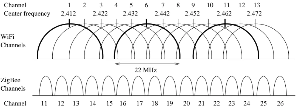
Wireless networks are more and more deployed in different areas of applications and in our everyday life. The WiFi standard, which is based on IEEE 802.11 standard [1], has been widely deployed in the past 25 years. The most used version of this standard uses the 2.4 GHz ISM band and is based on a random medium access control that allows different WiFi networks to coexist even when they are working on the same channel or overlapping channels. Nevertheless, it is highly recommended to use 5-channel separation to avoid interference because WiFi channels are overlapping as it is shown in figure 1. For example, channels 1, 6 and 11 in figure 1 are highlighted as possible 3 non-overlapping channels.
Another standard which has recently gained in popularity is ZigBee [2]. It is based on IEEE 802.15.4 standard [3]. ZigBee also uses the 2.4 GHz ISM band and is often deployed in areas where WiFi is already installed. Other more recently approved wireless standards such as WirelessHART [4] and ISA100.11a [5], that are proposed for industrial wireless sensor networks, are also based on the the physical layer of IEEE 802.15.4 and work in the 2.4 GHz ISM band. Figure 1 also shows how IEEE 802.15.4 channels overlap with those of the IEEE 802.11. WirelessHART and ISA100.11a are supposed to be deployed in more controlled environments such as indoor industrial monitoring and control applications and they are mostly based on TDMA (Time Division Multiple Access) and frequency hopping. Unlike ZigBee which is essentially based on CSMA/CA (Carrier Sense Multiple Access with Collision
Avoidance) for accessing the medium.
In most cases, these networks need to coexist in the same physical space and share the same bandwidth in the 2.4 GHz ISM band. The increasing number of applications using wireless technology is creating congestion in the 2.4 GHz frequency band and making the coexistence issue even more critical. Many studies have been done to evaluate the effect of the coexistence in this band as discussed in the state of the art of this paper.
In this paper, we study in great details the behaviour of slotted CSMA/CA of IEEE 802.15.4 in the presence on a WiFi network. Indeed, we investigate how WiFi affects the performance of slotted CSMA/CA algorithm in terms of additional delays caused on the backoff algorithm. Accord-ing to our knowledge, this level of analysis has not been done before. We give an in-depth analysis of the behaviour of CSMA/CA according to the relative positions of IEEE 802.15.4 transmitters and receivers and WiFi nodes. We show that the effect of WiFi on the transmitters is not the same as on the receivers. In addition, we will show how the effect of WiFi on IEEE 802.15.4 depends on the traffic load of WiFi. We also measured the interference in overlapping channels and non-overlapping channels. We also propose a new overhead estimation caused by the coexistence. In what follows we will refer to IEEE 802.15.4 as ZigBee and IEEE 802.11 as WiFi. The remainder of the paper is organized as follow. In section II we summarize some of the related work concerning coexistence in the 2.4 GHz band. In section III we describe how slotted CSMA/CA operates. In section IV we analyse the measurements from the different experiments that we did to evaluate to effect of WiFi on ZigBee and we present our overhead estimation. We conclude the paper in section V.
II. STATE OF THE ART
In the literature, many works have been done in this domain. These studies were limited to the Received Signal Strength Indicator (RSSI), the Packet Error Rate (PER), and the Link Quality Indicator (LQI).
In [6], authors made a survey on the coexistence problem of these 2 wireless standards and discussed the state of the art of the different evaluations that exist. The paper discusses
This work has been done with the collaboration of EDF R&D. We would like to thank Kevin Verny for his important contribution to the realization of the experiments and Andre Misson for providing the experimental site.
2.412 2.422 2.432 2.442 2.452 2.462 2.472 Center frequency Channel 1 2 3 4 5 6 7 8 9 10 11 12 13 22 MHz Channel WiFi Channels ZigBee Channels 20 21 22 23 24 25 26 11 12 13 14 15 16 17 18 19
Figure 1. The overlap between WiFi channels from 1 to 13 and the ZigBee channels from 11 to 26 in the 2.4 GHz spectrum.
the solutions and good practices to ensure none destructive coexistence based on frequency domain and time domain. These solutions for ZigBee standard, published in technical reports [7], [8], [9], [10], remain very costly such as re-porting interference on the current channel and asking the ZigBee coordinator to order a channel switch for the whole network. The paper also points out the lack in the literature of evaluations that differ between transmitters and receivers of IEEE 802.15.4, others studied the effect of the relative angles between the links of both technologies.
In [11], authors evaluated the effect of WiFi activity on ZigBee communications. Only the three following parameters RSSI, LQI and PER were evaluated. Results showed how the link quality degrade when the distance between the ZigBee communicating nodes increases. This was done for different channels of IEEE 802.15.4, different packet sizes for WiFi, and for both IEEE 802.11g and IEEE 802.11b. In addition, authors presented some simulation results using OPNET to investigate the end-to-end delay and the medium access delay. Authors concluded that cognitive radio should be enabled in ZigBee to cope with the coexistence.
Other studies have also been made by simulation such as [12] where authors concluded that throughput of ZigBee net-work decreases in the presence on a WiFi netnet-work. Evaluations where made on application level evaluations.
Authors in [13] conducted simulations and showed based on PER and BER results that using frequency agility can efficiently mitigate the effect of WiFi interference and enhance the performance of ZigBee networks.
In [14], authors studied the interference issue by analysis and simulation using OPNET. The only factor that was studied in this paper was the PER based on the collision timing and the Bit Error Rate (BER). The authors concluded that the activity of WiFi has very little effect on the the communication of IEEE 802.15.4 in two cases: if the WiFi interferer is more than 8 meters away from the IEEE 802.15.4 nodes, and if the frequency offset between the two technologies is bigger than 7 MHz.
In [15], authors also evaluated the interference of WiFi on IEEE 802.15.4 activity in terms of PER. Results are based
on real measurements using CC2420 Chipcon transceivers. In this paper authors tested a different type of Clear Channel Assessment (CCA) based only on the energy level but results were not compared to the normal CCA mode which takes into account the modulation conformity. They also evaluated the effect of Bluetooth and microwave ovens. Bluetooth caused bursty packet loss and microwave ovens have an impact only in very close range less than 1 meter away from the nodes.
In [16], authors also measured the coexistence effect on the PER by means of measurements. Consequences on both sides, that is on WiFi and on IEEE 802.15.4, were given. Results show that IEEE 802.15.4 is more damaged by the activity of WiFi than the other way around.
Other researchers such as [17], [18] and [19] focused on new techniques or equipment for eliminating the interference effect but these techniques or equipment are not currently supported by the standards or provided in standard hardware architecture. According to our knowledge, the study presented in this paper has never been done before.
III. IEEE 802.15.4SLOTTEDCSMA/CA
The IEEE 802.15.4 standard [3] supports two operational modes: (i) the beacon-enabled mode in which periodic beacon frames are transmitted by the coordinator to synchronize nodes according to a superframe structure depicted in Fig. 2, and (ii) the non-beacon-enabled mode in which unslotted CSMA/CA is used. In this paper, we focus on the beacon-enabled mode. Although the study could have been made on unslotted CSMA/CA, similar behaviour should be observed when unslotted CSMA/CA is used.
0 0 1 1 0 0 1 1 CAP CFP beacon beacon inactive SD (active) BI time
In the beacon-enabled mode, the superframe is divided into two periods: the CAP (Contention Access Period) during which slotted CSMA/CA is used to avoid collisions, and the CFP (Contention Free Period) where the coordinator allocates time slots for nodes to ensure that nodes transmit frames in a TDMA manner in order to avoid collisions. The interval that separates two consecutive beacons (BI) and the superframe duration (SD) are determined by two parameters: the super-frame order (SO) and the beacon order (BO). BI and SD are defined as follows:
(
BI= aBaseSuperframeDuration.2BO,
SD= aBaseSuperframeDuration.2SO,
where0 ≤ SO ≤ BO ≤ 14 and aBaseSuperframeDuration = 15.36 ms.
Two topologies are proposed by the standard: star and peer-to-peer. The peer-to-peer topology suffers from beacon frame collisions when the beacon-enabled mode is used (see proposals of Task Group 4b of IEEE 802.15.4 or [20], [21]). Thus, in what follows we only consider the star topology which covers the majority of deployed topologies.
Slotted CSMA/CA algorithm is applied before the transmis-sion of a data frame during the Contention Access Period of the superframe. This algorithm is based on a 320 µs time unit called backoff period. The boundaries of the backoff periods are aligned with the boundaries of the superframe slots. Any activity of the MAC sublayer (such as the channel sensing and the transmissions) starts at the boundary of a backoff period. Slotted CSMA/CA algorithm uses three variables: NB (Number of Backoffs), which is the number of times a backoff has been drawn for this transmission attempt, CW (Contention Window), which is the number of consecutive backoff periods during which a device senses the channel, and BE (Backoff Exponent) which defines the range of possible backoff periods a device waits for until it assesses the channel.
Figure 3 represents the steps of slotted CSMA/CA. In Step 1, the MAC sublayer initializes the three variables and locates the boundary of the next backoff period: NB is set to 0, CW is set to 2 and BE is set to 3. In Step 2, a random number of backoff periods is chosen from[0; 2BE − 1]. If the
number of remaining backoff periods in the CAP is less than the chosen random number, the MAC sublayer draws a new backoff at the start of the CAP of the next superframe.
Once the backoff has been decremented, the MAC sublayer makes sure that the remaining number of backoff periods in the CAP is enough to perform two CCAs (since CW= 2), to send
the frame and to receive the acknowledgment (if required). If this is the case, it proceeds to the next step. Otherwise, it waits for the start of the CAP of the next superframe and goes back to Step 2. This is called the CCA deference.
In Step 3, the MAC sublayer asks the physical layer to perform a CCA at the next backoff boundary. The next step depends on the result of the CCA. If the channel is assessed to be busy, the MAC sublayer goes to Step 4. Otherwise, it goes to Step 5. In Step 4, NB and BE are incremented, provided that BE does not exceed aMaxBE, and CW is set to 2. If NB
slotted CSMA/CA
NB= 0, CW = 2
BE= macMinBE
locate backoff period boundary delay for random (2BE − 1)
unit backoff periods perform CCA on backoff period boundary
channel idle? CW= 2, NB = NB + 1, BE= min(BE + 1, aMaxBE) CW= CW − 1 NB > macMaxNB? CW= 0? failure success (Step 1) (Step 2) (Step 3)
(Step 4) yes (Step 5)
yes yes
no
no no
Figure 3. IEEE 802.15.4 slotted CSMA/CA (without the battery life extension).
exceeds macMaxCSMABackoffs (denoted by macMaxCB. on the figure), the algorithm terminates with a channel access failure, otherwise it goes back to Step 2. In Step 5, CW is decremented. If CW reaches zero, the transmission begins at the boundary of the next backoff period. Otherwise, the MAC sublayer returns to Step 3.
IV. RESULTS OF COEXISTENCE
We conducted different experiments in order to measure the effect of WiFi on ZigBee. All experiments were done using Cisco Aironet access points with certified WiFi clients, and Texas Instruments (TI) wireless sensor nodes that implement IEEE 802.15.4 slotted CSMA/CA with a CC2420 transceiver [7]. WiFi traffic was generated without nearby IEEE 802.11b stations, RTS/CTS were not used, application layer acknowl-edgements were not used, and ERP-OFDM modulation with a short preamble was used. We made modifications on the TI code in order to obtain the different timing elements. TI nodes were connected to a computer using a serial cable and timing indicators for the node activity were logged on the computer. We studied the effect of WiFi duty cycle on the packet loss ratio of ZigBee in IV-A. In IV-B, we argue that a good link quality has better chances to resist to interferences, and in IV-C and IV-D we evaluate the overhead in terms of delay while
accessing the channel due to interferences. Details about each experiment as well as metrics that are evaluated are provided in each section.
Figure 4. Equipment used for the experiments. One Cisco Aironet access point and two TI ZigBee nodes. WiFi clients were used in order to generate traffic according to the different scenarios used in the experiments. Relative positions of the access point and ZigBee nodes change according to each experiment.
A. Effect of WiFi duty cycle
In what follows, we evaluated the effect of the WiFi traffic profile on the packet loss ratio of ZigBee. The goal behind this series of measurements is to find the threshold at which the WiFi traffic has no or little effect on the ZigBee traffic. We considered that 1% of packet loss is enough to judge that WiFi has an effect. Thus, we plotted the RSSI values of interference for each duty cycle when an effect is detected.
Indeed, low duty cycles represent low channel occupancy by WiFi. A duty cycle of 35% for example means that the WiFi channel is occupied only 35% of the time. We made measurements with the following WiFi traffic profiles:
• a duty cycle of 2,25% with UDP traffic at a 54 Mbps modulation,
• a duty cycle 5% with UDP traffic at a 24 Mbps modula-tion,
• a duty cycle 17,5% with UDP traffic at a 6 Mbps modulation,
• a duty cycle 23% with UDP traffic at a 24 Mbps modu-lation,
• a duty cycle 35% with UDP traffic at a 9 Mbps modula-tion,
• a duty cycle 44% with UDP traffic at a 12 Mbps modu-lation,
• a duty cycle 59% with TCP traffic at a 54 Mbps modu-lation,
• a duty cycle 88% with TCP traffic at a 6 Mbps modula-tion,
With these different WiFi traffic profiles we tested three scenarios: overlapping channels (WiFi on channel 11 and ZigBee on channel 23), adjacent channels (WiFi on channel 11 and ZigBee on channel 25), and non-overlapping channels (WiFi on channel 11 and ZigBee on channel 26).
Note that, when we a WiFi duty cycle of 88% has an effect on ZigBee at a given level of interference (-70 dBm for example), we conclude that there is no need to do additional tests for higher levels of interference. We generated only one ZigBee packet per second, and an acknowledgement is requested for each packet. Each message is 30-byte long.
Figures 5, 6 and 7 show the threshold that should not be exceeded in terms of received signal power observed at the receiver and the transmitter sides to avoid packet loss on the ZigBee traffic when WiFi and ZigBee channels are overlapping, adjacent and non-overlapping respectively.
Intereference on transmitter Interference on receiver −80 −70 −60 −50 −40 −30 −20 2.255 17.5 23 35 44 59 88 WiFi duty cycle.
RSSI threshold in dBm.
Figure 5. Threshold of RSSI of interference level that defines the limit not to be exceeded in order for WiFi to have no effect on ZigBee in terms of packet loss: overlapping channels.
Intereference on transmitter Interference on receiver −80 −70 −60 −50 −40 −30 −20 2.255 17.5 23 35 44 59 88 WiFi duty cycle.
RSSI threshold in dBm.
Figure 6. Threshold of RSSI of interference level that defines the limit not to be exceeded in order for WiFi to have no effect of ZigBee in terms of packet loss: adjacent channels.
Results show that when the interference is applied on the receiver, the effects on packet loss is more significant and start at lower RSSI values compared to the case where the interference is applied on the transmitter. Indeed, this is an expected result because on the transmitter side the node applies CSMA/CA and hope to get a chance to find the medium idle to send its packet. Once it starts transmitting the packet, it will not stop even if the channel becomes occupied. This is not the case for the receiver which needs to have lager windows of idle channel (channel non occupied by the WiFi traffic) in order
Intereference on transmitter Interference on receiver −80 −70 −60 −50 −40 −30 −20 2.255 17.5 23 35 44 59 88 WiFi duty cycle.
RSSI threshold in dBm.
Figure 7. Threshold of RSSI of interference level that defines the limit not to be exceeded in order for WiFi to have no effect of ZigBee in terms of packet loss: non-overlapping channels.
to successfully receive the packet during the whole period of reception. Thus, the risk of losing packets is higher on the receiver side. For example, in figure 5, if we consider a WiFi duty cycle of 23%, ZigBee receivers should not experience an interference level above -75 dBm in order to avoid packet loss.
B. Link quality effect
In the following scenario, we show that with a high RSSI level, the ZigBee link resists much better to WiFi perturbation. In order to do so, we maintained the same level of interference coming from WiFi traffic and we varied the RSSI level on the ZigBee link. Small RSSI values represent a low quality link and high RSSI values represent a high quality link.
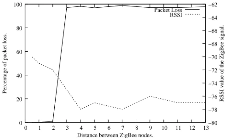
We put a WiFi access point at a 10-meter distance from the ZigBee receiver. The access point is transmitting a TCP traffic at 100 mW of transmit power using a 6 Mbps bit rate. The received signal power of WiFi at the ZigBee receiver is around -62 dBm. The WiFi channel is channel 11 and ZigBee channel is channel 23. We varied the distance between the ZigBee nodes between 50 cm and 13 m. The Zigbee transmitter is sending 1 message every 9 ms, each message is 110-byte long.
Packet Loss RSSI 0 20 40 60 80 100 0 1 2 3 4 5 6 7 8 9 10 11 12 13−80 −78 −76 −74 −72 −70 −68 −66 −64 −62
Percentage of packet loss.
RSSI value of the ZigBee signal.
Distance between ZigBee nodes.
Figure 8. Percentage of packet loss at the ZigBee receiver with different RSSI values of the ZigBee signal.
Results of figure 8 show that the ZigBee link can resist to perturbations from WiFi as long as the RSSI of the WiFi signal is not more than 10 dB above the RSSI value of the ZigBee signal. This phenomenon is related to what we call the capture effect in a wireless transmission [22].
C. Overhead of the coexistence
In what follows, we study the overhead of the coexistence in terms of additional delay that the ZigBee packets endure before accessing the medium. Indeed, we calculated the average delay for accessing the medium without the presence of interference and we considered that all additional average delays when a WiFi interference is present is an overhead generated by the coexistence. These delays would come from longer backoffs for successful transmissions, time spent on unsuccessful transmissions and repetitions. Thus, we computed the overhead according to the following formula in order to evaluate each of the additional delay sources:
Overhead =
(ADwP - ADwoP) + AAF*(NbF/NbS) + AAS*((NbS-NbR)/NbS), where
• ADwP (Average Delay with Perturbation) is the average medium access delay with the presence of WiFi interfer-ence,
• ADwoP (Average Delay without Perturbation) is the average medium access delay without WiFi interference, • AAF (Average Access Failure) is the average time for an
access failure to occur,
• NbF (Number of Failures) is the number of frames that were not transmitted due to failure to access the medium, • NbS (Number of Successes) is the number of frames that
were successfully transmitted,
• AAS (Average Access Success) is the average time for accessing the medium without errors,
• NbR (Number of Received) is the number of received frames.
Where,
• (ADwP - ADwoP) will give us the average additional delay due to interference from WiFi.
• AAF*(NbF/NbS) will give us the additional average time spent on trying to send frames that were not sent due to interference.
• AAS*((NbS-NbR)/NbS) will give us the additional aver-age time spent on repeating frames due to interference. In these scenarios, the ZigBee node that is being the object of interference will be suffering from an interference level at -65 dBm and the other node at -80 dBm in the first case. We have made the tests with 2 ZigBee traffic profiles. On one hand, a relatively low ZigBee traffic with one message of 30 bytes every second, each message is acknowledged and repeated 3 times in case the acknowledgement is not received. This traffic profile represents typical notification messages sent by sensors to a control center. And on the other hand, a very high traffic rate with one message of 30 bytes every
9 ms, messages are not repeated, but acknowledgements are kept for calculating the statistics. This profile represents the maximum transmission data rate with acknowledgements that we were able to generate using our motes without causing synchronization errors.
Results in figure 9 show that with the presence of WiFi interference, each ZigBee packet suffers between 30 ms and 55 ms of additional delay due to access delay, repetitions and packet loss. In addition, it is clear to notice that the overhead is higher when the interference is more significant on the transmitter. This is essentially due to the fact that when the transmitter is under high interference, it will struggle to send a frame and will keep waiting for an idle channel to be able to send it. This will cause significant delay before accessing the medium.
In addition, a high rate ZigBee traffic is more likely to suffer from interference because it is more likely to find the medium idle to receive or send packets when the number of packets is very high.
We also tested the high data rate profile with UDP WiFi traffic with 1 Mbps and 5 Mbps over a 6 Mbps modulation. As figure 10 shows, UDP generates less interference than TCP and the 1 Mbps generates less interference than the 5 Mbps. The overhead in additional delay reflects the consequences of these interferences. 000 000 000 000 000 000 000 000 000 000 000 111 111 111 111 111 111 111 111 111 111 111 000 000 000 000 000 000 000 000 000 000 000 000 111 111 111 111 111 111 111 111 111 111 111 111 000 000 000 000 000 000 000 000 111 111 111 111 111 111 111 111 000 000 000 000 000 000 000 000 000 000 111 111 111 111 111 111 111 111 111 111 000 000 000 000 000 000 000 000 000 000 000 000 000 000 000 111 111 111 111 111 111 111 111 111 111 111 111 111 111 111 000 000 000 000 000 000 000 000 000 000 000 000 000 000 000 000 000 000 000 000 000 000 111 111 111 111 111 111 111 111 111 111 111 111 111 111 111 111 111 111 111 111 111 111 000000 000000 000000 000000 000000 000000 000000 000000 000000 000000 000000 111111 111111 111111 111111 111111 111111 111111 111111 111111 111111 111111 000000 000000 000000 000000 000000 000000 000000 000000 000000 000000 000000 000000 111111 111111 111111 111111 111111 111111 111111 111111 111111 111111 111111 111111 00 00 11 11 0000 1111
low traffic rate high traffic rate Interference on the receiver
Interference on the transmitter
0 10 20 30 40 50 60 6
Overhead in additional delay in ms
Figure 9. Overhead: average additional delay due to interference with TCP traffic. 1 Mbps 5 Mbps 0000 0000 0000 0000 0000 0000 0000 0000 0000 0000 1111 1111 1111 1111 1111 1111 1111 1111 1111 1111 0000 0000 0000 0000 0000 0000 0000 0000 0000 0000 0000 0000 0000 0000 1111 1111 1111 1111 1111 1111 1111 1111 1111 1111 1111 1111 1111 1111 0 10 20 30 40 50 60
Overhead in additional delay in ms
Figure 10. Overhead: average additional delay due to interference with UDP traffic.
D. Overhead caused by interference with non-overlapping channels
In figure 11 we show the overhead on the ZigBee activity when we use channels 20 to 26 while WiFi is active on channel 6 with an interference level at around -30 dBm. Notice that interference on the transmitter has significantly more effect on the overhead than interference on the receiver, this is due to delays caused by extended backoffs and unsuccessful transmissions due to busy channel detections. On the other hand, when interference is applied to the receiver, overhead is mainly caused by collisions on the receiver that produce more repetitions.
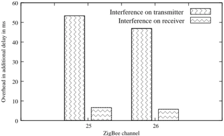
We did a similar experiment with WiFi on channel 11 and ZigBee on channels 25 and 26. We started with an interference level at -55 dBm and then -65 dBm. Results show significant overhead on channel 25 and on channel 26 when the interference level is at -55 dBm as shown in figure 12. In complementary results, with an interference level at -65 dBm there was no overhead on neither channels.
00 00 00 00 00 00 00 00 00 00 00 00 11 11 11 11 11 11 11 11 11 11 11 11 00 00 00 00 00 00 00 00 00 00 11 11 11 11 11 11 11 11 11 11 00 00 00 00 00 00 00 00 00 00 00 00 11 11 11 11 11 11 11 11 11 11 11 11 000 000 000 000 000 000 000 000 000 000 000 000 000 111 111 111 111 111 111 111 111 111 111 111 111 111 00 00 00 00 00 00 00 00 00 00 11 11 11 11 11 11 11 11 11 11 00 00 00 00 00 00 00 00 00 00 00 11 11 11 11 11 11 11 11 11 11 11 00 00 00 00 00 00 00 00 00 00 11 11 11 11 11 11 11 11 11 11 0 0 0 0 0 1 1 1 1 1 00 00 00 00 00 11 11 11 11 11 00 00 00 11 11 11 0 0 0 0 0 1 1 1 1 1 00 00 00 00 00 00 11 11 11 11 11 11 0 0 0 0 0 1 1 1 1 1 00 00 00 00 11 11 11 11 00 00 11 11 0000 1111 0 10 20 30 40 50 60 19 20 21 22 23 24 25 26 27
Overhead in additional delay in ms
ZigBee channel
Interference on transmitter Interference on receiver
Figure 11. Overhead with very high interference and non-overlapping channels.
000000 000000 000000 000000 000000 000000 000000 000000 000000 000000 000000 000000 000000 111111 111111 111111 111111 111111 111111 111111 111111 111111 111111 111111 111111 111111 000000 000000 000000 000000 000000 000000 000000 000000 000000 000000 111111 111111 111111 111111 111111 111111 111111 111111 111111 111111 000 000 000 111 111 111 000 000 000 111 111 111 000 000 111 111 00000 11111 Interference on transmitter Interference on receiver 0 10 20 30 40 50 60 25 26
Overhead in additional delay in ms
ZigBee channel
Figure 12. Overhead on non-overlapping channels 25 and 26 with -55 dBm WiFi interference.
V. CONCLUSION AND PERSPECTIVES
In this paper, we evaluated the effect of the coexistence between two wireless network standards IEEE 802.11 and IEEE 802.15.4. We showed that ZigBee is effected by WiFi on many levels: frame loss, frame repetitions, access delay, and consequently, energy consumption. But this is very related to the channel used in both standards. The effect is more signif-icant when dealing with overlapping or adjacent channels.
We made a very detailed analysis on the overhead caused by the presence of interference. We measured the additional delay and actions that a node might undergo before being able to correctly access the channel. The results of overhead can directly be converted to energy consumption overhead. Indeed, these operations are causing the nodes to consume more energy under the presence of interference.
Results showed that using ZigBee and WiFi in the same environment is possible if special precautions are taken into account. For example, placing the ZigBee nodes in places where the RSSI level of WiFi is below -65 dBm when possible will significantly protect ZigBee traffic from interference. Choosing non-overlapping channels is always encouraged. And if possible, reduce WiFi activity in such a way to avoid occupying the channel with very high duty cycles; duty cycles below 33% are very much encouraged.
Results in this paper only presented evaluations on link levels. In future works, experimentations should be made on network scale taking into account application scenarios. According to our results, application level results will very much depend on the level of exposure of the network to the interference and the importance of exposed links in relation to the application.
REFERENCES
[1] I. 802.11, “Part 11: Wireless LAN medium access control (MAC) and physical layer (PHY) specifications,” ANSI/IEEE, Standard 802.11 R2003, 1999.
[2] Zigbee, “Zigbee Specification,” ZigBee Standards Organization, Stan-dard Zigbee 053474r13, 2006.
[3] IEEE 802.15, “Part 15.4: Wireless medium access control (MAC) and physical layer (PHY) specifications for low-rate wireless personal area networks (WPANs),” ANSI/IEEE, Standard 802.15.4 R2006, 2006.
[4] HART Communication Foundation Std., “HART field communication protocol specifications,” Tech. Rep., 2008.
[5] International Society of Automation Std., “ISA100.11a: 2009 wireless systems for industrial automation: Process control and related applica-tions,” Draft standard, in preparation, 2009.
[6] D. Yang, Y. Xu, and M. Gidlund, “Wireless coexistence between ieee 802.11- and ieee 802.15.4-based networks: A survey,” International
Journal of Distributed Sensor Networks, vol. 2011, p. 17, 2011.
[7] Chipcon company, “CC2420 coexistence,” Tech. Rep., June 2006. [8] Crossbow Company, “ZigBee and wireless frequency coexistence,” Tech.
Rep., June 2007.
[9] SynapSense company, “Co-existence and security whitepaper,” Tech. Rep., July 2008.
[10] Crossbow Company, “Avoiding RF interference between WiFi and Zigbee,” Tech. Rep., July 2005.
[11] M. Rihan, M. El-Khamy, and M. El-Sharkawy, “On zigbee coexistence in the ism band: Measurements and simulations,” in ICWCUCA, August 2012.
[12] S. Arif and S. Supangkat, “Simulation and analysis of zigbee - wifi interference,” in ICT For Smart Society (ICISS), 2014 International
Conference on, Sept 2014, pp. 206–210.
[13] S. S. Wagh, A. More, and P. R. Kharote”, “Performance evaluation of IEEE 802.15.4 protocol under coexistence of wifi 802.11b,” Procedia
Computer Science, vol. 57, pp. 745 – 751, 2015, 3rd International
Conference on Recent Trends in Computing 2015.
[14] S. Shin, S. Choi, H. Park, and W. Kwon, “Packet error rate analysis of ieee 802.15.4 under ieee 802.11b interference,” in WWIC, May 2005. [15] A. Sikora and V. Groza, “Coexistence of ieee 802.15.4 with other
systems in the 2.4 ghz-ism-band,” in IEEE Instrumentation and
Mea-surement Technology Conference, August 2005.
[16] L. Angrisani, M. Bertocco, D. Fortin, and A. Sona, “Experimental Study of Coexistence Issues Between IEEE 802.11b and IEEE 802.15.4 Wireless Networks,” IEEE Transactions on Instrumentation and
Mea-surement, vol. 57, no. 8, 2008.
[17] G. Khanna and G. Gupta, “Eliminating the problem of coexistence between zigbee and wifi using EDCA synchronization and multi header transmission,” International Journal of Science and Research, vol. 4, 2015.
[18] P. Valck, I. Moerman, D. Croce, F. Giuliano, I. Tinnirello, D. Garlisi, E. Poorter, and B. Jooris, “Exploiting programmable architectures for wifi/zigbee inter-technology cooperation,” EURASIP Journal on Wireless
Communications and Networking, vol. 2014, no. 1, p. 212, 2014.
[Online]. Available: http://jwcn.eurasipjournals.com/content/2014/1/212 [19] S. Jacob and P. Ravi, “Enabling coexistence of ZigBee and WiFi,”
Communications on Applied Electronics, vol. 2, 2015.
[20] A. Koubaa, A. Cunha, and M. Alves, “A time division beacon schedul-ing mechanism for IEEE 802.15.4/Zigbee cluster-tree wireless sensor networks,” Poly. Institute of Porto, Tech. Rep. TR-070401, April 2007. [21] G. Chalhoub and M. Misson, “Cluster-tree based energy efficient pro-tocol for wireless sensor networks,” in IEEE International Conference
on Networking, Sensing and Control, 2010.
[22] K. Whitehouse, A. Woo, F. Jiang, J. Polastre, and D. Culler, “Exploiting the capture effect for collision detection and recovery,” in IEEE