HAL Id: hal-01825992
https://hal.archives-ouvertes.fr/hal-01825992
Submitted on 15 Oct 2020
HAL is a multi-disciplinary open access
archive for the deposit and dissemination of
sci-entific research documents, whether they are
pub-lished or not. The documents may come from
teaching and research institutions in France or
abroad, or from public or private research centers.
L’archive ouverte pluridisciplinaire HAL, est
destinée au dépôt et à la diffusion de documents
scientifiques de niveau recherche, publiés ou non,
émanant des établissements d’enseignement et de
recherche français ou étrangers, des laboratoires
publics ou privés.
Integrated Framework for Model-Driven Systems
Engineering: A Research Roadmap
Hamzat Olanrewaju Aliyu, Mamadou Kaba Traoré
To cite this version:
Hamzat Olanrewaju Aliyu, Mamadou Kaba Traoré. Integrated Framework for Model-Driven Systems
Engineering: A Research Roadmap. TMS/DEVS Symposium on Theory of Modeling & Simulation
(TMS/DEVS 2016) 2016 Spring Simulation Multi-Conference (SpringSim’16), Apr 2016, Pasadena,
CA, United States. �10.23919/TMS.2016.7918834�. �hal-01825992�
Integrated Framework for Model-Driven Systems
Engineering: A Research Roadmap
Hamzat Olanrewaju Aliyu
1,21
School of Info. & Communication Technology
Federal University of Technology Minna,
Gidan-Kwanu Campus, Minna, Nigeria
[email protected]
Mamadou Kaba Traor´e
2 2LIMOS CNRS UMR 6158
Universit´e Blaise Pascal, Clermont-Ferrand II,
Campus des C´ezeaux, Aubire CEDEX, France
[email protected]
ABSTRACT
In recent decades, Model-Driven Engineering (MDE) prac-tices have continuously aided the adoption of system analysis approaches like simulation, formal analysis and enactment by non-expert users. However, due to limited portability of mod-els between different approaches, exhaustive analysis of com-plex systems still depend largely on creating disparate mod-els designated for different analysis goals to get complemen-tary solutions to the problem. Productivity and efficiency of the process can be greatly improved by integrating the differ-ent approaches in a framework which offers a unified model-ing interface and automated synthesis of all required artifacts. This paper suggests a framework as a roadmap for further re-search towards realizing this goal. First we present the archi-tecture of the framework, then we present the steps to build the syntax of the unified formalism at its kernel and an illus-trative case study as a proof of concept for the proposal.
Author Keywords
SimStudio; HiLLS; Language Integration; Model-Driven Systems Engineering.
ACM Classification Keywords
I.6.2 SIMULATION AND MODELING (Simulation Lan-guages, Model Validation and Analysis, Simulation Support Systems): .
1. INTRODUCTION
Efficient d esigns o f c omplex s ystems r equire i terative pro-cesses of modeling, performance evaluation, logical analysis and implementation for run-time testing [17]. Evaluation and analysis methodologies such as simulation, Formal Methods (FM) and enactment are often used to study different aspects of systems to mine subtle realities about properties of interest. For example, simulation studies may be used to predict sys-tem’s performance, identify problems and their causes, and so on [7, 24]. Uses of FM include rigorous and exhaustive ex-ploration of model properties like completeness, consistency, safeness, liveness to give the assurance that a system will al-ways produce desired results [9, 39]. Enactment [10, 15], applied to a Discrete Event System (DES) may be described
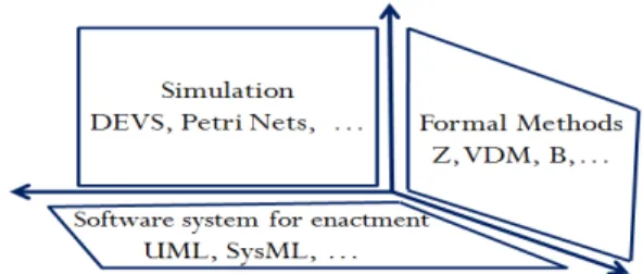
Figure 1. World view of model-based analysis methodologies.
as the execution of its software prototype using the physical clock time as the operational reference for the scheduling and execution of events. An enactment model should practically stand in for the real system in a physical environment by act-ing out its expected characteristics. Enactment can be used as a proof that a certain theory or concept or technology works or otherwise [16].
Since no one analysis methodology can sufficiently investi-gate all aspects of a system, there is need for collaborations between tools that provide best answers to different questions. In principle, these approaches are practised in isolation as de-picted by the orthogonal planes described in Figure 1. There-fore, there are little chances of portability of models between development environments. Arguably, this phenomenon is not sustainable as the burden of learning many formalisms to create and update multiple models of yet the same system can be too much to bear especially for non-expert users.
In recent decades, there have been considerable research ef-forts to establish transformations between models in separate planes. For instance, research efforts to combine DEVS sim-ulation models and FM include [20, 34, 36, 40]. Also, combi-nation of FM and software models have been proposed in [6, 21, 22] while [26, 27, 38] present some of the efforts to in-tegrate simulation and software development. However, lit-tle progress has been made in making elements of the three orthogonal planes available in a framework which offers a unified formalism to integrate model-based engineering tools and facilitate communications among practitioners with di-verse interests and concerns.
An overview of a recently published edited series of model-based systems engineering articles [13] suggests that the need for combining systems engineering processes with system architecture languages and simulation methods is gradually gaining recognition among researchers. In a similar
con-text, we propose a roadmap to achieve the consistent coexis-tence of the three disparate model-based systems engineering methodologies in Figure 1 within a unified framework. This paper combines and elaborates on our previous sugges-tions in [3, 4] on how to build a unified framework for Model-Driven Systems Engineering (MDSE). We suggest a frame-work that has at its kernel, a generic modeling language that is used at its front-end for model specification. i.e., a lan-guage that is not particularly dedicated to any of the three methodologies but which is expressive enough to unambigu-ously capture the details required by each methodology and communicable enough to enhance fruitful discussions among experts from all sides.
The idea is inspired by the fact that, observably, nearly the same set of DES concepts are described in the different planes but in different forms and at different levels of refinement. For example, in all cases, a DES description specifies con-cepts like state, state transition, input, output, components, exchange of messages/events, etc. while a few more unique concepts may be added in each case to be able to answer spe-cific questions. Thus, we can arguably say that, essentially, the main disparities are created by the languages used and their associated semantics. Therefore, it would be fair to pro-vide a common representation of the concepts in a way to foster communication among experts of the different fields and support automated generation of the models required by their tools. We envisage that this approach will lead to reduce cost and improved productivity in Model-Driven Systems En-gineering (MDSE). The next section provides backgrounds in some techniques to be applied in subsequent sections to develop our proposal. Then we present the proposed frame-work in Section 3 and its unified language in Section 4. We provide a case study in Section 5 as a proof of concept. Sec-tion 6 compares our approach with related work. Finally, we provide concluding remarks and perspectives in Section 7.
2. BACKGROUND
2.1 Discrete Event System Specification (DEVS)
As part of the background to later sections of this paper, we assume the reader has at least a minimum idea of DEVS, hence we do not dwell on it. If necessary, the reader may consult [41] for an introduction to the formalism.
2.2 Object-Z
Object-Z [30] is an Object-Oriented extension of the Z spec-ification language [31]. It adopts the concept of class in Ob-ject Orientation to add structure, modularity and clarity to Z specifications. The main units of specification in Z are the schemas. i.e., state schemas that declare state variables with possible invariants and operation schemas that manipulate the state schema(s) to produce state transition events. On top of the Z’s notion of schema, Object-Z introduces the concept of class to describe a system as enclosing a state schema and all the operation schemas that manipulate and/or use its declared variables. Object-Z class also exhibits Object-Orientation properties like inheritance, encapsulation and polymorphism.
Figure 2. Template of Object-Z class.
Figure 2 is a template for specifying an Object-Z class, the ba-sic building block for system specification in Object-Z, show-ing its possible elements and the orders in which they may appear.
• Class Name is the class’ identifier in a specification. The header may also specify some generic parameters. • Visibility list of class elements that can be accessed from
outside the class in similitude to public attributes and meth-ods in Object-Orientation.
• An Inherited Class designates an existing class whose def-inition is imported for reuse.
• A Local Definition may be a local type or constant defini-tion (usually specified in an axiomatic schema) or a refer-enceto another class.
• The state schema declares the system’s state variables and invariants(if any). This may be followed by a specification of the system’s initial/starting state.
• Operations specify the computations that use and/or ma-nipulate other elements of the class
2.3 Model-Driven Engineering/Architecture (MDE/MDA)
Model-Driven Engineering (MDE) [5, 18, 28] is a modern Software Engineering approach that considers everything as a model in similitude to the way everything is considered an object in Object-Oriented approaches. Governed by the slogan Model once, generate any where, MDE’s vision is a world of software development in which models can be used, at different phases, to communicate and understand problems and, subsequently, to drive the synthesis of executable pro-gram codes.
Model-Driven Architecture (MDA) [19] is a realization of MDE initiated by the Object Management Group (OMG). MDA introduces a conceptual framework, with a set of stan-dards at different layers, to define models, and transforma-tions between models. The top layer of MDA contains the Platform-Independent Model (PIM) which specifies the func-tions of a system under without paying attention to technol-ogy platforms that will be used for implementation. The PIM may be used to drive the generation of one or more Platform-Specific Models (PSMs) in the next layer. Each PMS is ex-pected to contain some technical details about the platform to be used for implementation. Finally, each PSM drives the synthesis of program codes at the lowest layer.
MDA approaches enable modelers to separate essential busi-ness concerns from the details of implementation platforms; thereby enhancing efficient solution designs, increased pro-ductivity and reduced development time.
2.4 Meta-model Integration Techniques
In MDE, the syntax of a modeling language is defined by a meta-model. In essence, it defines the concepts described in a language and the relationships between them. In this subsec-tion, we give brief descriptions of three techniques, presented in [11], for integrating meta-models to define new languages. These techniques will be applied in Section 4.1 to define a modeling language.
Meta-model merge
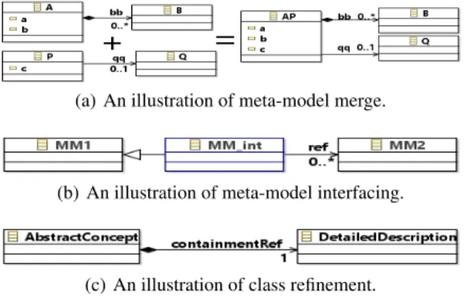
The meta-model merge is used to combine integrate inde-pendent meta-models that share some common abstractions of real world entities - a phenomenon referred to as concept collision. The common concepts are used as the seam(s) to merge them into a unified whole. It is similar to the pack-age merge mechanism [42] that recursively take the unions of model elements (in different packages) matched by name and meta-type. Meta-model merge is, however, different in two ways: (1) it occurs at class level instead of package level, and (2) Common concepts do not necessarily have to match by name in meta-model merge. Once matching classes are iden-tified, the two classes cease to exist but merge into a new class in the integrated meta-model; the new class encompasses all attributes and associations of the source classes. An illus-tration of the application of meta-model merge is given in Figure 3(a). Considering that classes A and P in separate meta-models have been identified to match, then they can be merged into class AP as described in the figure
Meta-model Interfacing
Meta-model interfacing is employed to combine two meta-models describing distinct but related domains in order to explore the relationships between them. Its implementa-tion requires the introducimplementa-tion of new classes and relaimplementa-tions (that do not necessarily belong to either of the two source meta-models) which serve as the interface between the dis-tinct meta-models through associations. The technique is described in Figure 3(b) with MM1 and MM2 representing classes in separate meta-models and MM int representing the interface class introduced to establish relationships between them.
(a) An illustration of meta-model merge.
(b) An illustration of meta-model interfacing.
(c) An illustration of class refinement.
Figure 3. Metamodel integration techniques.
Class refinement
Class refinement is used to establish relationships between closely related (or in fact, same concepts) expressed at dif-ferent levels of refinement in two independent meta-models. Specifically, a hierarchical containment relationship is cre-ated between the two meta-models fragments ( as described in Figure 3(c)) with the more abstract fragment as the con-tainer(s) of the more detailed descriptions provided by the other.
3. AN INTEGRATED FRAMEWORK FOR MODEL-DRIVEN SYSTEMS ENGINEERING
3.1 Overview of SimStudio
The SimStudio was first proposed in [35] to bridge the gap between theoretical advancement in simulation modeling and prospective end users. The idea was to aggregate technologi-cal implementations of the theories of modeling and Simula-tion and formal analysis of simulaSimula-tion results in one platform and establish collaborations between tools through model transformations. Further work on the project [33] proposed to use DEVS Markup Language (DML) [32], an XML markup language for DEVS, at the kernel of the framework as a stan-dard for model representation. The choice of DEVS as the principal formalism is premised on its expressiveness and universality for simulation modeling [37] which also makes it suitable for establishing interoperability between heteroge-neous simulation models; this is achieved by translating mod-els created using other formalisms into DML which is subse-quently used to drive the generation of DEVS-based simula-tion codes.
3.2 SimStudio II
SimStudio, in its current state, is more focused on simulation-based approach to model-simulation-based systems engineering. The SimStudio II extends the current solution to encompass for-mal analysis and enactment for exhaustive analysis of sys-tems without complicating the modeling process. As a roadmap for this ongoing research, we have discussed a sum-mary of our proposal in [3]; the rest of this paper elaborates on the framework’s architecture and suggests guidelines for realizing its components.
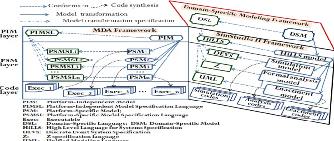
Figure 4 shows the architecture of SimStudio II vis-`a-vis the MDA framework. The left part of the diagram depicts the MDA framework described previously in Section 2.3. As a basic tenet of model-driven developments, every model is created with a specification (modeling) language; thus, a model conforms to the language that produced it. In the PIM layer, the PIM conforms to PIMSL. Similarly, every PSM conforms to its PSMSL. It is also reasonable to say that the model transformation from the PIM to any PSMn is an in-stance of the model transformation specification from PIMSL to PSMSLn. Finally, program codes are synthesized from the PSMs for their respective target platforms. It is important to note that the term ”Platform” in PIM and PSM is contextual; i.e., it may refer to operating system, programming language, hardware, etc. it is used in the context of the SimStudio II architecture to mean any of the three model-based analysis methodology (i.e., simulation, formal analysis or enactment).
Figure 4. Architecture of SimStudio II framework.
The SimStudio II architecture is described on the right side of Figure 4. It takes cue from the MDA framework by defining three layers each describing the same category and standard of models as proposed in MDA framework. In the PIM layer, we propose a PIMSL called HiLLS (High Level Language for System Specification) to define discrete event system models - HiLLS model - that are not meant solely for any of the three analysis approaches discussed in this paper. Further details on HiLLS are provided in the next section.
In the PSM layer, we propose to use DEVS, Z and UML as PSMSLs for simulation, formal analysis and enactment mod-els respectively. Our choices of these formalisms are based on three premises: Firstly, the considered universality of each of them in its domain. For instance, DEVS has been proven to be a common denominator for simulation formalisms by Vangheluwe [37], Z is considered suitable for modeling a wide range of state-based systems for formal analysis and UML currently still the choice of the majority for object-oriented software design communication. Secondly, they all allow for separation of modeling and implementation con-cerns, i.e., models can be defined by concentrating on the problems without being influenced by the operational imple-mentation of the solutions. Lastly, they all enjoy diversified tool supports; hence, we can reuse existing tools in our frame-work.
With the model transformation specifications from HiLLS to the three PSMSLs in the PSM layer, it is considered that HiLLS is expressive enough to coherently represent all in-formation required by the three target platforms. Therefore, a HiLLS model is separately translated into simulation, formal analysis and enactment models that are instances of DEVS, Z and UML respectively. Subsequently, executable codes (code layer) will be synthesized from the PSMs based on the target programming environment supported by the language tools. As the principal formalism at the kernel of SimStudio II, HiLLS offers a highly communicable graphical concrete syn-tax for model editing and communication among
stakehold-ers. This is also in line with MDE’s principle of ”model once and generate anywhere” and we envisage that with this ap-proach, model-based systems engineering can replicate the feats of productivity and timeliness achieved in software en-gineering through the use of MDE.
In addition to being the glue for integrating the disparate anal-ysis approaches, HiLLS also serve as the extension point or interface through which the framework may provide compu-tational analysis support different domains such as business processes, healthcare systems analysis, communications, etc. This is illustrated by the Domain-Specific Modeling Frame-work built on top of SimStudio II frameFrame-work in Figure 4. If the domain concepts can be described as discrete event sys-tems, then there is likelihood that model transformation rules can be specified between the DSL and HiLLS so that any model, DSM, of the domain can be translated to HiLLS mod-els to take benefits of the computational supports possible in SimStudio II. We will discuss the specification of HiLLS in the next section.
4. HILLS
In order to be expressive enough to actualize the visions of SimStudio II, the HiLLS’ syntax describes an integrated set of constructs for modeling systems for its three target plat-forms. The build up to the syntax is shown in Figure 5. Start-ing from the bottom (purposes) row, we identified the con-ventional approach to model systems for each purpose in the “Approaches” row. Next we selected considerably universal formalisms for each approach in the second row.
We discussed the premise for choosing DEVS in the previ-ous sub-section. We also discussed the universality of Z for formal methods, the basis for choosing Object-Z for the com-bined logic and object-orientation approaches is that Object-Z already integrates Object-Z and object-oriented concepts as de-scribed previously in Section 2.2. Therefore, the abstract syntax of HiLLS is derived from the integration of DEVS and Object-Z concepts using the meta-model integration tech-niques introduced in Section 2.4
4.1 Abstract Syntax
We present a simplified HiLLS’ abstract syntax in Figure 6. It integrates system-theoretic concepts from DEVS and soft-ware engineering concepts from Object-Z to produce a co-herence whole. Interestingly, the set of concepts described by the two formalisms have a significant amount of intersection; for instance, they both describe the concepts of state, state transition, input, output, hierarchical compositions and con-nections between components, albeit in different ways and at different levels of refinement. Therefore, the set of con-cepts described in HiLLS is just a union of those described in DEVS and Object-Z while we use the meta-model merge and meta-model refinement techniques (see Section 2.4) to address the concept collisions and refinement gaps respec-tively. The dashed box at the south-east of Figure 6 contains most of the abstract system-theoretic concepts adopted from DEVS. A system is described by the class HSystem which is composed of configurations, transitions, couplings, ports, and hComponents. Using the meta-model merge and inter-facing techniques, class HClassifier serves as the bridge be-tween the DEVS and Object-Z concepts. Through HClas-sifier, HSystem inherits the Object-Z concepts StateSchema
Figure 6. Simplified HiLLS’ abstract syntax.
to formally declare state variables, and Operation to encap-sulate computation algorithms. Moreover, using meta-model refinement, Object-Z’s Predicate and Expression are used to provide detailed specifications of the property and sojourn-Timerespectively of configuration where a configuration is a set of states that satisfy the same constraints called proper-ties. Similarly, the concept Declaration in Object-Z refines the definition of Port. HiLLS’ syntax is described in greater details in [2].
4.2 Concrete Syntax
Figure 7(a-h) presents the graphico-textual notations for rep-resenting HiLLS models. We adopt UML-like notations to represent the structures of models so as to take advantage of the popularity of the later to ease the learning of the language. An HSystem (b) is denoted by a box similar to the UML class except that it has a stack of four compartments as against three in UML class and that the second compartment of HSystem has interfaces containing input and output ports to its left and right sides respectively. The second compartment contains the state schema and axiomatic schema within which state variables and system parameters respectively are declared. The third compartments contain the definitions of operations respectively. The system’s behavior is described by the con-figuration transition diagram in the fourth compartment. Fig-ures 7(c - e) denote the configurations. The symbol fc in the third compartment of finite configuration (d) holds the expres-sion that produces its sojourn time. Passive (c) and transient (e) configurations have predefined sojourn times positive in-finity and zero respectively; hence they are not explicitly rep-resented in the model. The three kinds of configuration tran-sitionsare denoted by the different labeled arrows in (g) with
the computation expressions accompanying the transitions as the labels of the arrows.
We are unable to provide detailed mappings of HiLLS’ con-cepts to the target languages (semantics domains) due to space constraint; we will illustrate the essential correspon-dences with a case study in the next section. We have pre-sented the simulation semantics in [2, 23] and the formal and enactment semantics will be reported in future publications.
5. CASE STUDY: THE TRAFFIC LIGHT SYSTEM
As a proof of concept of the work presented in this paper, we provide a small case study to illustrate model-driven systems engineering in the SimStudio II. Figure 8 shows a HiLLS specification of a traffic light system and the corresponding simulation, formal analysis and enactment models obtained from the HiLLS specification.
5.1 HiLLS Specification of Traffic Light PIM
The HiLLS model at the north-west region of Figure 8 presents a platform-independent model of a simple traffic
light system. In this example, we only consider the basic op-eration of the traffic light, extra functionalities such as call buttons for pedestrians are not considered. The system has no input port; it, however, has an output port, out, of type String. It has two state variables f 1 and f 2 both of type integer with their possible values constrained as specified in the predicate part of the state schema. A constant parameter timeSlice of type integer is also defined with its value initialized in the init operation.
The system’s behavior is modeled by the configuration tran-sition diagram in the lower compartment of the diagram. It has three configurations: brake, stop and move. They are assumed respectively only when the predicates f 1 == 2, f 1 == 1 ∧ f 2 == 0, and f 1 == 1 ∧ f 2 == 1 are true. They are all finite configuration; hence, the sojourn time of each configuration is specified by the expression assigned to the symbol ft in the third compartment of the configuration figure. For instance, f t = 1.5 ∗ timeSlice for brake. The starting configuration is brake. The labeled arrows model the transitions between configurations with the labels specifying
the computations accompanying them. The transition from braketerminates on stop if the condition f 2 == 0 is true; otherwise, it terminates on move.
The exclamation mark ”!” depicts an output and a primed, ’, state variable specifies its final value after the transition. For instance the sequence of expressions out!“red”; f 10 = 1; on the transition to stop specify that first, the value ”red” is sent on the output port out, then the value of f 1 is set to 1. If the computation algorithm is too long to be conveniently placed on the transition arrow, the modeler can put the algorithm in an operation and just call the operation where ever it is needed.
5.2 Derived Simulation Model
The DEVS model derived from the HiLLS specification of traffic light is shown in the south-east region of Figure 8. Since the system has no components, an atomic DEVS model is inferred. Essentially, the DEVS state set, S, is built from the state schema, axiomatic schema and the configurations in the HiLLS specification. They are derived as name-domain pairs in S. A new variable, phase, is introduced whose domain is the set of configuration names defined in the HiLLS model. The predicate part of S is derived from the predicates of the configurations. Configuration transitions in HiLLS map to corresponding DEVS state transitions; hence, only DEVS in-ternal transition function is derivable from the model. The δintfunction is derived from the sources and targets of HiLLS
configuration transitions. Similarly, DEVS λ function is de-rived from the HiLLS model by mapping a configuration name to the outputs (if any) accompanying the transition(s) originating from the configuration. Finally, DEVS ta func-tion derives from a mapping of configurafunc-tion names to their respective sojourn times.
5.3 Derived Formal Analysis Model
The Z model derived for formal analysis is presented in the south-west region of Figure 8. From the HiLLS state schema, a replica Z state schema is created with a secondary state vari-able, phase, whose type is the finite set of configuration la-bels specified in the HiLLS model and the predicates of the configurations are added to the predicate part of the Z state schema so-derived. Similarly, HiLLS’ axiomatic schema is transferred to Z as-is. Each configuration transition in HiLLS translates to an operation schema in Z which modifies the state schema. If a transition involves an input event (resp. output event), an input variable (resp. output variable) corre-sponding to the declaration and type of the port concerned is added to the operation schema. The properties of the source configuration (in conjunction with conditions satisfied by the transition if any) map to the precondition of the Z operation schema while the final values of the state variables after the transition map to the post condition of the derived operation schema.
5.4 Derived Enactment Model
We have proposed, in a previous work [1], an object-oriented framework for the enactment of DES. The framework com-bines foundational theory of DES with the observer pat-tern [12]. Based on the template provided by the framework,
we derive an enactment model for this case study and an ex-cerpt is shown in the north-east region of Figure 8.
6. RELATED WORK
In his Doctoral dissertation, Shuman [29] proposed a multi-dimensional analysis framework in which the three method-ologies integrated in SimStudio II are considered fundamen-tal to the study of executable architectures. The thesis studied the different dimensions in terms of they are specified and ex-ecuted, and their underlying formal semantics in order to map several solutions to understand which methods are mature. SimStudio II goes further to identify the commonalities in the abstract system concepts that can be specified in the disparate dimensions of analysis through the chosen formalisms; using the commonalities as seams, we derive a new meta-model to provide a unified front-end for the three domains of analysis. Hong and Kim [17] have canvassed for unified frameworks with facility for iterative process of modeling, performance evaluation, logical analysis and implementation for run-time testing for efficient designs of complex systems. They pro-posed the DEVS Specification Language (DEVSpecL), an EBNF (Extended Backus-Naur Form) notation for DEVS to drive a DEVS-based framework system design. The idea was to translate a DEVSpecL model into Abstract Syntax Tree (AST) through lexical and syntactic analyzers so that the DE-VSpecL AST is used to check ill-structured coupling rela-tions and type mismatch of states/events by a type checker. Then the checked DEVSpecL AST becomes the source for the generation of different forms of codes which are exe-cuted with various tools for model verification, logical analy-sis, performance evaluation, and others. It is not clear, how-ever, the technology used to generate codes for the variety of tools. Also, DEVSpecL models are close to C++ programs; with the current model-driven technologies, we think a high level language should be used in the position of DEVSpecL to improve communicability of system designs among stake-holders and accessibility to non-expert users.
Cetinkaya et al. [8] maintains Modeling and Simulation (M&S) projects can be treated as software development processes and can be facilitated by model-driven devel-opment approaches. They proposed, therefore, Model-Driven Development Framework for Modeling and Simula-tion (MDD4MS) which includes an M&S life cycle, meta-model definitions for the conceptual meta-modeling, specification and implementation stages, model transformations for the suggested meta-models and a tool architecture for the over-all process. A prototype was presented which uses a graphi-cal editor Business Process Modeling Notations (BPMN) for conceptual modeling. A partial model-to-model transforma-tion between the BPMN and DEVS meta-model was also pre-sented using ATLAS Transformation Language (ATL). The DEVS model so generated is expected to drive the generation of simulation code based on DEVS Distributed Simulation Object Library (DSOL), a Java-based simulator library. Sim-Studio II is different from MDD4MS in a number of ways. The modeling interface provided by MDD4MS, BPMN, is suitable to express a very restricted set of discrete event sys-tems (DES) being a DSL. SimStudio II offers HiLLS at the
front-end which is expressive enough to describe more evolv-ing systems; it also offers the possibility to support DSLs in-cluding BPMN. Therefore, users can describe a mental model of a system in HiLLS even when no DSL exists for the do-main of the problem. Moreover, while the target of MDD4MS is a framework to facilitate simulation modeling lifecycle, SimStudio II seeks to offer a federation of different model-based engineering techniques, including simulation, for ex-haustive study of complex systems.
Mittal and Martin [25] have proposed the DEVS Unified Process (DUNIP), a framework to integrate research find-ings on DEVS theory to facilitate systems M&S. essentially, DUNIP focuses interoperability at modeling level while hid-ing the simulator engines in a net-centric environment. Like MDD4MS, the modeling interface of DUNIP consists of DSL model editors such as BPMN, UML, SysML at the client side while the DEVS simulation virtual machine resides on the server side. At the interface between the DSLs and the net-centric simulator, there the DEVS Modeling Language (DE-VSML) which provides a platform-independent DEVS rep-resentation of systems that is used by the simulator middle-ware to generate simulation codes for DEVS-based and non DEVS-based simulation tools in different programming plat-forms. The objectives of DUNIP highlights the verification and validation simulation results, no further details were pro-vided on how it may be achieved in DUNIP. Also, there is no ambition of logical analysis of models themselves. This marks one significant difference between DUNIP and the work presented in this paper. Moreover, the DEVSML-based PIM is essentially meant to foster interoperability between M&S tools, the PIM in SimStudio II (HiLLS) is to promote communication and collaboration among practitioners of dis-parate model-based systems engineering methods, in addition to tools integration. It is, however, important to mention that while DUNIP supports model-driven systems engineering in a net-centric environment, SimStudio II does not offer this feature in its present stage.
7. CONCLUSIONS AND PERSPECTIVES
We propose the SimStudio II, an MDA-based framework to integrate theoretical and technological advancements in MDSE and make them available through a unified high-level modeling interface to enhance communication among practi-tioners and automated synthesis of models for studying dif-ferent aspects of complex systems. Technically, the frame-work has a graphical modeling language, HiLLS, at its kernel which combines DES concepts from system theory and soft-ware engineering to express models in a generic way to al-low for automated synthesis of models for simulation, formal analysis and enactment.
This paper presents the architecture of the framework and the syntax of HiLLS. As a proof concept, we also presented a case study to illustrate how a HiLLS model can serve as com-mon reference to generate models conforming to disparate formalisms for simulation, formal analysis and enactment of DES. We expect that this work suggests a sound roadmap for, and stimulates, further research into making theoretical ad-vancements in model-based analysis approaches, including
simulation, easily accessible to prospective users as well as the co-existence of disparate analysis methodologies for ex-haustive studies of complex systems.
In an ongoing project, we are currently building an im-plementation of the proposal using the Eclipse Modeling Projects [14]. Particularly, a graphical model editor for HiLLS is being developed as a plug-in for Eclipse. When completed, we intend to use its meta-model as the source of model transformation and code generation processes target-ing existtarget-ing simulation, formal analysis and enactment frame-works. We expect that it will provide an environment to ac-commodate a federation of MDSE tools to facilitate the con-struction of high fidelity models and exhaustive analysis of systems of diverse disciplines.
ACKNOWLEDGMENTS
We thank the anonymous reviewers for their insightful com-ments and suggestions.
This work is supported by the Nigerian National Information Technology Development Agency (NITDA) through a Doc-toral grant to the first author under the NITDEF postgraduate scholarships scheme.
REFERENCES
1. Aliyu, H. O., Ma¨ıga, O., and Traor´e, M. K. A framework for discrete event systems enactment. In Proc.ESM 2015, EUROSI-ETI (2015), 149–156.
2. Aliyu, H. O., Ma¨ıga, O., and Traor´e, M. K. The High Level Language For System Specification: A
Model-Driven Approach to Systems Engineering. Int. J. Model. Simul. Sci. Comput(2016),
DOI:10.1142/S17939623164100389.
3. Aliyu, H. O., and Traor´e, M. K. Toward an integrated framework for the simulation, formal analysis and enactment of discrete event systems models. In Proc. WSC 2015, IEEE (2015), 3090–3091.
4. Aliyu, H. O., and Traor´e, M. K. Towards a unified framework for holistic study and analysis of discrete event systems. In Proc. AUSTECH 2015, AUST (2015). 5. B´ezivin, J. In search of a basic principle for model
driven engineering. Novatica 5, 2 (2004), 21–24. 6. Bousse, E., Mentr´e, D., Combemale, B., Baudry, B., and
Katsuragi, T. Aligning SysML with the B method to provide V&V for systems engineering. Innov. Sys. and Soft. Eng. 6, 1 (2010).
7. Carson II, J. S. Introduction to modeling and simulation. In Proc. WSC 2004, IEEE (2004), 9–16.
8. Cetinkaya, D., Verbraeck, A., and Seck, M. D. Mdd4ms: A model driven development framework for modeling and simulation. In Proc. SummerSim 2011, SCS International (2011), 113–121.
9. Clarke, E. M., and Wing, J. M. Formal methods: State of the art and future directions. Computing Surveys (CSUR) 28, 2 (1996), 626–643.
10. Dowson, M., and Fernstr¨om, C. Towards requirements for enactment mechanisms. In Proc. EWSPT 1994, Springer Berlin Heidelberg (1994), 90–106. 11. Emerson, M., and Sztipanovits, J. Techniques for
metamodel composition. In Proc. OOPSLA 2006 (2006), 123–139.
12. Gamma, E., Helm, R., Johnson, R., and Vlissides, J. Design patterns: elements of reusable object-oriented software. Addison-Wesley, 1994.
13. Gianni, D., D’Ambrogio, A., and Tolk, A. (Eds.) Modeling and Simulation-Based Systems Engineering Handbook. CRC Press, 2014.
14. Gronback, R. C. Eclipse modeling project: a domain-specific language (DSL) toolkit. Pearson Education, 2009.
15. Holmlid, S., and Evenson, S. Prototyping and enacting services: Lessons learned from human-centered methods. In Proc. QUIS 2007 (2007).
16. Holmquist, L. E. Prototyping: Generating ideas or cargo cult designs? Interactions 12, 2 (2005), 48–54.
17. Hong, K. J., and Kim, T. G. DEVSpecL: DEVS specification language for modeling, simulation and analysis of discrete event systems. Information and Software Technology 48, 4 (2006), 221–234.
18. Kent, S. Model driven engineering. In Proc. IFM 2002, Springer (2002), 286–298.
19. Kleppe, A. G., Warmer, J. B., and Bast, W. MDA explained: the model driven architecture: practice and promise. Addison-Wesley Professional, 2003.
20. Kuhn, D. R., Craigen, D., and Saaltink, M. Practical application of formal methods in modeling and simulation. In Proc. SummerSim 2003, SCS International (2003), 726–731.
21. Laleau, R., Semmak, F., Matoussi, A., Petit, D., Hammad, A., and Tatibouet, B. A first attempt to combine SysML requirements diagrams and B. Innov. in Syst. Soft. Eng..
22. Lano, K., Clark, D., and Androutsopoulos, K. Uml to b: Formal verification of object-oriented models. In Proc. IFM 2004, Springer (2004), 187–206.
23. Ma¨ıga, O., Aliyu, H. O., and Traor´e, M. K. A new approach to modeling dynamic structure systems. In Proc.ESM 2015, EUROSI-ETI (2015), 141–148. 24. Maria, A. Introduction to modeling and simulation. In
Proc. WSC 1997, IEEE (1997), 7–13.
25. Mittal, S., and Martin, J. L. R. Model-driven systems engineering for netcentric system of systems with devs unified process. In Proc. WSC 2013, IEEE (2013), 1140–1151.
26. Nikolaidou, M., Dalakas, V., and Anagnostopoulos, D. Integrating simulation capabilities in sysml using devs. In Proc. SysCon 2010, IEEE (2010).
27. Schamai, W., Fritzson, P., Paredis, C., and Pop, A. Towards unified system modeling and simulation with modelicaml: Modeling of executable behavior using graphical notations. In Proc. Modelica 2009 (2009), 612–621.
28. Schmidt, D. C. Guest editor’s introduction: Model-driven engineering. Computer 39, 2 (2006), 25–31.
29. Shuman, E. A. Understanding the elements of executable architectures through a multi-dimensional analysis framework. Doctoral Dissertation, Old Dominion University Norfolk, VA, USA, 2011.
30. Smith, G. The Object-Z specification language. Springer Science & Business Media, 2012.
31. Spivey, J. M. Understanding Z: a specification language and its formal semantics. Cambridge Univ. Press, 1988. 32. Touraille, L., Traor´e, M. K., and Hill, D. R. A mark-up
language for the storage, retrieval, sharing and interoperability of devs models. In Proc.
SpringSim-TMS/DEVS 2009, SCS (2009), p. 163. 33. Touraille, L., Traor´e, M. K., and Hill, D. R. A
model-driven software environment for modeling, simulation and analysis of complex systems. In Proc. SpringSim-TMS/DEVS 2011, SCS (2011), 229–237. 34. Traor´e, M. K. Analyzing static and temporal properties
of simulation models. In Proc. WSC 2006, IEEE (2006), 897–904.
35. Traor´e, M. K. Simstudio: a next generation modeling and simulation framework. In Proc. SimuTools 2008, ICST (2008), p. 67.
36. Trojet, M. W., Frydman, C., and Hamri, M. E. Practical application of lightweight z in devs framework. In Proc. SpringSim 2009, SCS International (2009), p. 154. 37. Vangheluwe, H. L. Devs as a common denominator for
multi-formalism hybrid systems modelling. In Proc. CACSD 2000, IEEE (2000), 129–134.
38. Viehl, A., Sch¨onwald, T., Bringmann, O., and Rosenstiel, W. Formal performance analysis and simulation of uml/sysml models for esl design. In Proc. EDAST 2006, EDAA (2006), 242–247.
39. Wing, J. M. A specifier’s introduction to formal methods. Computer 23, 9 (1990), 8–22.
40. Yacoub, A., Hamri, M., and Frydman, C. A method for improving the verification and validation of systems by the combined use of simulation and formal methods. In Proc. DSRTA 2014, IEEE (2014), 155–162.
41. Zeigler, B. P., Praehofer, H., and Kim, T. G. Theory of modeling and simulation: integrating discrete event and continuous complex dynamic systems. Academic press, 2000.
42. Zito, A., Diskin, Z., and Dingel, J. Package merge in uml 2: Practice vs. theory? In Proc. MoDELS 2006, Springer Berlin (2006), 185–199.