HAL Id: hal-00168673
https://hal.archives-ouvertes.fr/hal-00168673
Submitted on 29 Aug 2007HAL is a multi-disciplinary open access
archive for the deposit and dissemination of sci-entific research documents, whether they are pub-lished or not. The documents may come from
L’archive ouverte pluridisciplinaire HAL, est destinée au dépôt et à la diffusion de documents scientifiques de niveau recherche, publiés ou non, émanant des établissements d’enseignement et de
Localization of light in a lamellar structure with
left-handed medium : the light wheel
Paul-Henri Tichit, Antoine Moreau, Gérard Granet
To cite this version:
Paul-Henri Tichit, Antoine Moreau, Gérard Granet. Localization of light in a lamellar structure with left-handed medium : the light wheel. Optics Express, Optical Society of America - OSA Publishing, 2007, 15 (23), pp.14961. �hal-00168673�
hal-00168673, version 1 - 29 Aug 2007
Localization of light in a lamellar structure with
left-handed medium : the light wheel
P. H. Tichit, A. Moreau and G. Granet
LASMEA, UMR CNRS 6602, Universit´e Blaise Pascal,
24 avenue des Landais, 63177 Aubi`ere, France.
Abstract
The contra-directional coupling between a left-handed monomode waveguide and a right-handed monomode waveguide is rigorously studied using a complex plane anal-ysis. Light is shown to rotate in this lamellar structure forming a very exotic mode which we have called a light wheel. The light wheel can be excited using evanescent coupling or by placing sources in one of the waveguides. This structure can thus be seen as a new type of cavity. It is a way to suppress the guided mode of a dielectric slab.
Left-Handed Materials (LHM) present si-multaneously negative permittivity and per-meability. Such materials were a pure theo-retical oddity[1] until the recent experimental demonstration of the negative refraction[2]. Left-handed materials can be made using meta-materials, i.e. periodical structures with a period smaller than the wavelength, which behave as a homogeneous medium. Conse-quently to these works the LHM have aroused huge interest. It clearly appeared that LHM had hardly been studied although they could lead to structures presenting highly noncon-ventional behaviours : they seemingly allow to overcome the Rayleigh limit[3] and could even lead to invisibility[4]. In a large num-ber of situations, LHM behave the opposite way of conventional (right-handed) dielectric materials. This is of course the case for re-fraction (so that LHM are sometimes said to present a negative index), but for the Goos-H¨anchen effect as well[5, 6]. Generally, lamel-lar structures made with left-handed mate-rials present exotic properties. It has been shown for instance that a LHM slab could support backward or forward guided modes[10] and backward or forward leaky modes [7, 8, 9].
In this paper we present the study of the contra-directional coupling between a guided mode supported by a dielectric slab and a backward mode supported by a left-handed slab[10]. We show that this structure behaves as an edge-less cavity because light rotates inside the structure, and that the modes in-volved in this behaviour can be excited either using a prism coupler or by a source in one of the waveguides - leading to the formation of a “light wheel”. Such a cavity would be obtained without introducing any type of de-fect, as in the case of photonic crystals.
The considered structure is presented
fig-ure 1 : two slabs are surrounded by air and separated by a distance h. The upper slab, whose thickness is called h1, presents a
rela-tive permittivity of ǫ1 and a relative
perme-ability µ1 while the lower slab, whose
thick-ness is h2, is characterized by ǫ2 and µ2. This
rather simple structure allows analytical cal-culations and a rigorous analysis of the contra-directional coupling using complex plane anal-ysis - which is almost never done.
We will search for solutions which present a harmonic time dependence and which do not depend on y - just like the geometry of the problem. With these assumptions, the solutions can be either TE polarized (i.e. the electric field is polarized along the y axis) or TM polarized (the magnetic field being polarized along the y axis). In this work, we will only consider the TE case but the same study can be carried out for the TM case, leading to the same conclusions. We will hence seek a solution for which Ey(x, z, t) =
E(z) exp(i(α x − ω t)) with ω = k0c = 2π λ c
where λ is the wavelength in the vacuum. In the following, we will consider that λ is the distance unity (i.e. we take λ = 1).
h h 1 2 ε1 ε2 µ2 µ1 h I II III IV V x O z
Figure 1: The two waveguides are surrounded by air and separated by a thickness h. The z= 0 plane is placed in the middle of the air layer (region III). The different regions are labelled using roman numerals.
The function E(z) in a medium j charac-terized by ǫj and µj is in general a linear
with γ2
j + α2 = ǫjµjk02. Since we are only
interested in guided modes, we will consider that α > k0 so that the electric field is
de-caying exponentially in the air (we will note γ0 =
q
α2− k2
0). Above and under the
waveg-uides (in regions I and V) only one decaying exponential term remains. In this case, the continuity relations at an interface between two different media can be written as a ho-mogeneous system of equations. A non null solution can thus be found only if the deter-minant of the system is null, which can be written x1F1+x2F2+(1+x1x2F1F2) tanh(γ0h) = 0 (1) where Fj = 1−xx jtan(γjhj) j+tan(γjhj) and xj = γj µjγ0
what-ever the sign of ǫj or µj. Relation (1) is the
dispersion relation because each zero of the left part is a mode supported by the struc-ture.
The coupling of the two waveguides ap-pears when the upper and the lower waveg-uides, taken separately, both support a guided mode for the same constant propagation, called α0. First we have chosen a small thickness for the right-handed slab (ǫ1 = 3, µ1 = 1,
h1 = 0.2 λ) so that is behaves as a monomode
waveguide and we have computed α0. If the
two waveguides are identical (both right-handed and with the same thickness) the structure supports two propagating modes with two close and real propagation constants. The excita-tion of these two modes gives raise to an os-cillation of the energy between the two guides as shown figure2.
When the lower waveguide is left-handed (with ǫ2 = −3, µ2 = −1), its thickness has to
be chosen carefully to ensure a perfect cou-pling with the above slab. Using the disper-sion relation of the left-handed waveguide[10] we have chosen the thickness of the LHM slab (h2 = .7146 λ) so that (i) it supports no
fun-Figure 2: The two identical coupled waveg-uides of height 0.2 λ are excited using evanes-cent coupling : an incident beam with an in-cidence angle of 36, 9 in a medium with ǫ = 5 and µ = 1 is used. The energy oscillates be-tween the two guides and leaks out when it is in the upper guide, so that it decays expo-nentially.
damental mode (which would otherwise prop-agate forward) and (ii) the only supported mode is more localized in the LHM and hence propagates backward.
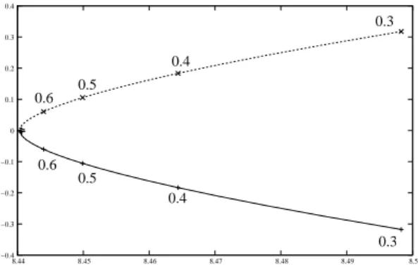
With the above parameters the dispersion relation is verified only for complex values of α : the two different solutions have then the same real part but opposite imaginary parts (i.e. conjugate propagation constants). The solution in the complex plane are shown fig-ure 3 for different values of h.
0.6 0.5 0.4 0.3 0.4 0.5 0.6 0.3 −0.4 −0.3 −0.2 −0.1 0 0.1 0.2 0.3 0.4 8.44 8.45 8.46 8.47 8.48 8.49 8.5
Figure 3: Solutions of the dispersion relation in the α complex plane for different values of h, which is given for some points as a frac-tion of the wavelength. The waveguides are characterized by h1 = 0.2 λ, ǫ1 = 3, µ1 = 1,
ǫ2 = −3, µ2 = −1 and h2 = .7146 λ. The
units correspond to the choice λ = 1.
the solutions, which are shown figure 4. Fig-ure 4 shows the modulus, the phase and the time-averaged Poynting vector along the x di-rection for the solution corresponding to the propagation constant with a positive imagi-nary part with h = 0.5. The solution is an hy-brid mode, since the field is important in both waveguides (see figure 4 (a)). The field in the right-handed medium and the field in the left-handed medium are un phase quadrature : there is a phase difference of π
2 in between
as shown figure 4 (b). Since the propaga-tion constant of the other solupropaga-tion is the con-jugate of the one represented figure 4, then the solution itself is the conjugate of the first one. The only difference between the two so-lutions is hence the phase, so that in both cases there is a phase quadrature between the two guides. This is very different from what happens with co-directional coupled waveg-uides in which the two gwaveg-uides are in-phase or out-of-phase, depending on the considered mode (see figure 2).
The time-averaged Poynting vector along the x direction is shown figure 4 (c). As ex-pected, it is negative in the LHM and posi-tive elsewhere. It is very interesting to note that the overall power flux of each mode is found to be null. This means that all the en-ergy that is sent in one direction by one of the waveguides comes back using the other one. This helps to understand the nature of the modes : although they have an im-portant real part of the propagation constant along the x axis, they can be considered as evanescent modes because they do not con-vey any energy. It is then difficult to define a propagationdirection, but the imaginary part of the propagation constant suggests that the modes actually have a direction in which they developp. When the imaginary part is posi-tive, the mode is decaying when x is
increas-ing. It is thus expected to developp towards the right - otherwise it would diverge. This means that the other mode developps in the other direction. This is a discussion which is usually applied to leaky modes[9].
(b) (c) (a) z Modulus Phase Poynting vector z V IV III II I −3.5 −3 −2.5 −2 −1.5 −1 −0.5 0 0.5 −2 −1.5 −1 −0.5 0 0.5 1 1.5 2 −40 −30 −20 −10 0 10 20 30 −2 −1.5 −1 −0.5 0 0.5 1 1.5 2 0 1 2 3 4 5 6 −2 −1.5 −1 −0.5 0 0.5 1 1.5 2
Figure 4: Characteristics of the solution with a propagation constant presenting a posi-tive imaginary part for h = 0.5 λ. Figure (a) shows the modulus of the field (which presents two zeros in the left-handed guide), figure (b) the phase, which is either null or equal to π in one guide and to π
2 in the other
one, and figure (c) shows the Poynting vector along the x direction.
Let us just underline that these two modes, having the same real part of their propagation constant, cannot be excited separately. They can be excited using evanescent coupling, i.e. using an incident beam propagating in a high-index medium close to the waveguides. When the incidence angle of the beam is greater than the critical angle, the waveguided modes can be excited. Figure 5 shows such a situa-tion. The field is clearly enhanced in the two waveguides, and the structure of the mode in the left-handed slab is particularly visi-ble. The most striking feature is the fact that there is a dark zone just above the incident beam in the closest slab. It is produced by the superposition of the two modes - and the center of the beam is the only place where it
may happen since the modes develop in dif-ferent directions. Such a dark zone could be expected after all, this is the case figure 2 -but in the lower waveguide. This is actually a characteristic of this particular coupling and it persists even when the two slabs are ex-changed.
Figure 5: Excitation of the light wheel us-ing an incident beam in a high-index mate-rial (with ǫ = 5 and µ = 1). The image rep-resents the modulus of the Ey field in a
do-main which is only 4.5 λ high and about 60 λ large. The propagation direction of light is in-dicated by white arrows so that the rotation of light in the structure is made visible. The fringes above the structure are localized inter-ferences of the incident and reflected beams. The profiles of the modes are in perfect agree-ment with figure 4. Notice the dark zone just under the incident beam. The incident angle of the beam is 36.9, the distance between the prism and the first waveguide is 0.5 λ.
Finally, when the two modes are excited they form what we called a light wheel : the light is heading to the right in the right-handed waveguide and to the left in the left-handed slab. On the right of the incident beam, the energy flows from the right-handed slab to the left-handed slab. This is the contrary on the left of the beam, so that light globally rotates inside the structure. In the case of an evanescent coupling, the reflected beam is distorted because of the excitation of the light wheel - but it is distorted symetrically
if the coupling is good enough. Such a sim-ple structure could then be used to perform beam reshaping[11].
The previous results suggest that despite its lamellar geometry the structure can be considered as a cavity. To ensure that an atom placed inside a waveguide is actually coupled with the light wheel we have com-puted the Green function of the problem. Fig-ure 6 shows the Green function when a source is place in the middle of the dielectric slab, and the light wheel is clearly excited. More precisely, two contra-rotative light wheels are excited and interfere.
Figure 6: Modulus of the electric field when a punctual source is placed in the middle of the right-handed waveguide. Two contra-rotative light wheels are excited and they interfere which explains the interference fringes.
In conclusion, we have shown that the use of a left-handed medium in a lamellar struc-ture could lead to a new type of phenomenon : the rotation of light which would then form a light wheel. This phenomenon could be used for beam reshaping, or even as a new type of cavity. It is an original way to suppress any propagative mode in a dielectric slab.
The properties of the structure are likely to be improved. Using Bragg mirrors could for instance enhance the quality factor of such a cavity by hindering light from leaking out of the structure. We believe that this study brings a new evidence that left-handed
ma-terials are renewing the physics of lamellar structures in photonics[12].
The authors would like to thank D. Fel-bacq and E. Centeno for fruitful discussions. This work is supported by the ANR project POEM.
References
[1] V.G. Veselago. The electrodynamics of substances with simultaneously negative values of ǫ and µ. Usp. Fiz. Nauk., 92:517, 1967.
[2] R.A. Shelby, D.R. Smith, and S. Shultz. Experimental verification of a negative index of refraction. Science, 292:77, 2001.
[3] J. B. Pendry. Negative refraction makes a perfect lens. Phys. Rev. Lett., 85:3966, 2000.
[4] J.B. Pendry, D. Schuring, and D.R. Smith. Controlling electromagnetic fields. Science, 312:1780, 2006.
[5] P.R. Berman. Goos-hanchen shift in neg-atively refractive media. Phys. Rev. E, 66:067603, 2002.
[6] A. Lakhtakia. On plane wave remit-tances and goos-hanchen shifts of pla-nar slabs with negative real permittiv-ity and permeabilpermittiv-ity. Electromagnetics, 23:71, 2003.
[7] L.G. Wang and S.Y. Zhu. Large nega-tive lateral shifts from the kretschman-raether configuration with left-handed materials. Appl. Phys. Lett., 87:221102, 2005.
[8] A. Moreau and D. Felbacq. Comment on ’large negative lateral shifts from the kretschman-raether configuration with left-handed materials’. Appl. Phys. Lett., 90:066102, 2007.
[9] A. Moreau and D. Felbacq. Leaky modes of a left-handed slab.
[10] I.V. Shadrivov, A.A. Sukhorukov, and Y.S. Kivshar. Guided modes in negative-refractive-index waveguides. Phys. Rev. E, 67:057602, 2003.
[11] I.V. Shadrivov, A.A. Sukhorukov, and Y.S. Kivshar. beam shaping by a peri-odic structure with negative refraction. Appl. Phys. Lett., 82:3820, 2003.
[12] I.V. Shadrivov, A.A. Sukhorukov, and
Y.S. Kivshar. Complete band gaps
in one-dimensional left-handed periodic structures. Phys. Rev. Lett., 95:193903, 2005.