HAL Id: hal-02171463
https://hal.archives-ouvertes.fr/hal-02171463
Submitted on 2 Jul 2019
HAL is a multi-disciplinary open access
archive for the deposit and dissemination of
sci-entific research documents, whether they are
pub-lished or not. The documents may come from
teaching and research institutions in France or
abroad, or from public or private research centers.
L’archive ouverte pluridisciplinaire HAL, est
destinée au dépôt et à la diffusion de documents
scientifiques de niveau recherche, publiés ou non,
émanant des établissements d’enseignement et de
recherche français ou étrangers, des laboratoires
publics ou privés.
A multi-domain platform of safety process methods and
tools for critical embedded systems.
Jean-Paul Blanquart, Eric Armengaud, Philippe Baufreton, Quentin
Bourrouilh, Joseph Machrouh, Andreas Mitschke, Markus Oertel, Thomas
Peikenkamp, Tormod Wien
To cite this version:
Jean-Paul Blanquart, Eric Armengaud, Philippe Baufreton, Quentin Bourrouilh, Joseph Machrouh,
et al.. A multi-domain platform of safety process methods and tools for critical embedded systems..
Embedded Real Time Software and Systems (ERTS2012), Feb 2012, Toulouse, France. �hal-02171463�
A multi-domain platform of safety process methods and tools
for critical embedded systems
Jean-Paul Blanquart1, Eric Armengaud2, Philippe Baufreton3, Quentin Bourrouilh2, Joseph Machrouh4, Andreas Mitschke5, Markus Oertel6, Thomas Peikenkamp6, Tormod Wien7
1 Astrium Satellites, 31 rue des cosmonautes, 31402 Toulouse Cedex 4, France (contact author: jean-paul.blanquart@astrium.eads.net, +33 5 62 19 69 56, fax …71 58)
2 AVL, Graz, Austria
eric.armengaud@avl.com, quentin.bourrouilh@avl.com 3 Sagem Défense Sécurité, Massy, France
philippe.baufreton@sagem.com 4 Thales, Palaiseau, France joseph.machrouh@thalesgroup.com
5 EADS, Hamburg, Germany andreas.mitschke@eads.net 6. OFFIS, Oldenburg, Germany markus.ortel@offis.de, peikenkamp@offis.de
7 ABB, Billingstad, Norway tormod.wien@no.abb.com
Abstract. The CESAR project1 aims at elaborating a Reference Technology Platform usable across several application domains (Aeronautics, Automotive, Industrial Automation, Railway and Space) for the cost effective development and validation of safety related embedded systems. Safety and, more generally, dependability are therefore major topics addressed by the project. This paper focuses on the work performed on safety requirements and approaches to be supported by a common Reference Technology Platform. We analyse and compare the industrial practice, applicable standards and state of the art so as to identify which and how safety views should be supported. This is achieved in particular through the incorporation of the necessary safety concepts in the CESAR Meta Model. We then focus on the major axes investigated by the project, formal model-based techniques for requirements engineering and component-based engineering. Incremental realisations and case studies confirm the interest and provide refined requirements for the final version of the platform.
Keywords: Safety, dependability, embedded
systems, standards, multi-domains, development and validation platform
1 The CESAR project (“Cost efficient methods and
processes for safety relevant embedded systems”) has received funding from the ARTEMIS Joint Undertaking under grant agreement n° 100016 and from specific national programs and/or funding authorities.
1 Introduction
The industry of safety critical embedded systems faces difficult challenges with more and more complex systems with more and more functions and interacting functions, very strong requirements on safety and safety justification, and very strong constraints on cost and time-to-market.
In this context, advanced engineering methods appear as very promising, in particular formal model-based methods addressing requirements engineering and component-based engineering. Building on these approaches, the CESAR European project (Joint Undertaking ARTEMIS) gathers more than 50 partners from academia, technology providers and industrial end-users from five application domains (Aeronautics, Automotive, Industrial Automation, Railway and Space). They aim at elaborating a Reference Technology Platform (RTP) usable across several application domains for the cost effective development and validation of safety related embedded systems. Safety and, more generally, dependability are therefore major topics addressed by the project.
This paper reports on the objectives, work and current achievements of the project from the safety point of view. This encompasses a survey of standards, state of the practice and of the art, the incorporation of the safety concepts in the CESAR Meta Model, and the elaboration and implementation of solutions in requirements engineering and component-based engineering. Assessments on industrial use cases provide refined requirements for the final version of the RTP.
2 State of the art and of the practice
Altogether the academic, technology and industrial partners of the CESAR project elaborated a collection and synthesis of the state of the practice and state of the art in safety related embedded systems in all five application domains covered by the project: aeronautics, automotive, industrial automation, railway and space, addressing the applicable standards, the industrial practice, state of the art, and identifying the support expected from the CESAR Reference Technology Platform, in particular under the form of “safety views”.
2.1 Safety standards
In terms of safety, the concern of this paper, we especially focused on the safety standards applicable to the target application domains and to their analysis and comparison:
•••• Aeronautics: Eurocae/SAE documents
ED-79A/ARP-4754A “Guidelines for Development of Civil Aircraft and Systems” [1] with the complements on methods and techniques ED-135/ARP-4761 “Guidelines and methods for conducting the safety assessment process on civil airborne systems and equipment” [2], completed by the Eurocae/RTCA documents on software (ED-12B/DO-178B “Software considerations in airborne systems and equipment certification” [3] and ED-80/DO-254 “Design Assurance Guidance for Airborne Electronic Hardware” [4]);
•••• Automotive: the new standard,
published in 2011, ISO 26262 “Road vehicles – Functional safety” [5];
•••• Industrial automation: the generic
standard IEC 61508 “Functional safety of electrical/electronic/ programmable electronic safety-related systems” [6] and its derived standards such as IEC 61511 “Functional safety – Safety instrumented systems for the process industry sector” [7];
•••• Railway: the EN CENELEC standards
50126 (“Railway applications – The specification and demonstration of reliability, availability, maintainability and safety (RAMS)”) [8], 50128 (“Railway applications – Communications, signalling and processing systems – Software for railway control and protection systems”) [9] and 50129 (“Railway applications – Communications, signalling and processing systems –
Safety related electronic systems for signalling”) [10];
•••• Space the ECSS standards Q30 (“Space
product assurance – dependability”) [11], Q40 (“Space product assurance – safety”) [12] and Q80 (“Space product assurance – software”) [13].
Even though there are differences in the standards applicable to the various domains, there are also many strong common principles and approaches [14], confirming the interest of a common platform to support the development and validation of safety-critical or safety-related embedded systems in the various domains. In particular all analysed standards propose a top-down risk-based approach and the consideration of several levels or categories for the consequences of failures and therefore categories for the systems and elements. This leads in particular to categories of requirements applicable to the development and assurance in consideration of the severity of failure consequences and associated overall occurrence probability of a system failure.
There are however also many differences, for instance in the details of the rules to allocate categories along the design, as well as on the architecture principles (e.g., with focus on “integrated safety” in aeronautics and automotive versus “external safety monitoring” in automation, rail and space), on the nature of the standards (e.g., prescriptive in terms of objectives versus means, or promoting explicitly or not the safety demonstration under the form of a “safety case”). Consequently the CESAR Reference Technology Platform cannot be a single common platform shared “as is” by all users, but rather a generic platform with all necessary facilities to be instantiated in each domain taking into consideration also the various industrial practices as well as the most promising methods and tools to support the development of safety critical embedded systems and in particular formal model-based and component-based approaches for requirements engineering and development.
2.2 Safety process and methods: the safety views
Industrial practice, following applicable standards, has developed and implemented a safety approach based on a strong process combining a global top-down safety construction and assurance process, supported by several methods and techniques aiming at supporting the elaboration and evaluation of architecture solutions and their implementation. The support that the CESAR Reference Technology Platform is expected to provide to these safety process, methods and techniques can be described through the notion of safety views and viewpoints.
Following IEEE 1471 [15] we define a view as “a representation of a whole system from the
perspective of a related set of concerns”, and a viewpoint as “a specification of the conventions for constructing and using a view; a pattern or template from which to develop individual views by establishing the purposes and audience for a view and the techniques for its creation and analysis”.
Therefore a view conforms to a viewpoint that establishes the conventions by which this view is depicted, created and analysed. The viewpoint determines the languages to be used to describe the view, and any associated modelling method or analysis technique to be applied to the view. So, a viewpoint is described by objectives, a set of concerns, modelling and language features and analytic methods. A view may consist of several models, and a model may participate in several views.
In the context of this work we propose the relevant safety and dependability views and viewpoints based on the identification of the relevant safety and dependability analysis techniques, and on which models these analyses could be performed. Therefore a safety and dependability viewpoint is defined as:
•••• A model i.e., a set of information and
their inter-relationships, with formal semantics of information and relations (the modelling and language features that allow performing the analyses of concern),
•••• A set of analytic methods that can be
applied to the model so as to analyse and assess some predefined safety and dependability properties.
Various categories of safety and dependability analysis techniques can be identified, corresponding to various categories of objectives, depending on the different stakeholders concerned with the safety of the system to be developed. Depending on the domain the stakeholders may be represented by different roles in the development process: e.g. a dedicated quality or safety manager is compliant with the standards applicable for the domain. Within the development process they also represent certification authorities, as well as customers concern with respect to safety.
Additionally, safety is a concern across the different engineering phases, implying various approaches depending on the development phase addressed. Early stages of the safety lifecycle aim at the identification of requirements and exploration of the implications of design whereas later lifecycle stages focus on the successful implementation of the requirements. Typical safety analysis techniques
as in particular required by safety standards include:
•••• Hazard analysis and risk assessment, •••• System Safety Assessment, generally
supported by Fault Tree Analysis, Failure Modes, Effects (and Criticality) Analysis, Common Cause Analysis, etc.,
•••• Verification and validation, in particular
of the implementation of safety and functional safety requirements.
These various safety analysis techniques can be classified, taking into consideration different categories of their objectives:
Quantitative (probabilistic) assessment of safety and dependability properties:
The purpose is to evaluate global probabilistic properties of a system (or of a part of it) based on its architecture (especially in terms of redundancies) and a set of assumptions on the stochastic distribution of failures that can affect the system and its elements. There are numerous modelling approaches and associated tools such as Markov Chains, Reliability Block Diagrams, Fault Trees etc., and component failure rate data bases. Even though some difficulties and limitations may exist, they are mainly related to the relevance of the component failure rates (for which model-based approaches in the sense of the study are of little support if any) rather than on the capability to combine them and evaluate safety and dependability probabilistic properties at a higher level. Nevertheless in case of complex system architecture and reconfiguration mechanisms, elaborating a model to conduct these evaluations remain tedious and error prone. It is therefore expected that the CESAR RTP will provide facilities to support the elaboration of such models.
Qualitative (descriptive and/or deterministic) assessment of propagation of faults and failures and of the effects of this propagation:
This corresponds to a very important and large set of analyses of the effectiveness of detection and protection mechanisms against faults and their combinations, analyses of common mode failures or common cause faults and their effects, etc. This must be a major target for CESAR considering the importance of the associated objectives and the limitations of the currently used techniques (e.g., Failure Modes, Effects and Criticality Analysis, Fault Tree Analysis and various check-lists). An assisted, if not automated, generation of the analysis reports from an engineering model annotated with the relevant information about fault occurrence and propagation is expected to be particularly useful.
Assessment (correctness, performance) of fault tolerance mechanisms:
Similarly to the correctness or performance assessment of any function, model-based approaches can be used provided they represent the behaviour of the function as well as, for performance evaluation, its utilisation of the relevant resources with respect to the target evaluation (time, memory, etc.). This can also be identified as an important target for CESAR because of the current difficulties and limitations of the definition and validation techniques applicable to fault tolerance mechanisms. Precisely these difficulties come from the increasing complexity of the fault tolerance mechanisms and their detailed behaviour, taking into account multiple interactions between a large number of elements (and moreover in nominal and degraded conditions).
Soundness, completeness of the safety and dependability arguments:
Formal models could be used to represent and check the safety and dependability logical argumentation (how the various pieces of evidence are logically combined to support a high level safety or dependability claim). This is mentioned here mainly for completeness because despite its interest in general and its possible inclusion among the topics addressed by the CESAR project, it is very different in nature from the techniques addressed by the study in the sense that the concerned models are specific to the considered safety and dependability analysis, rather than engineering models (even augmented and annotated with safety and dependability specific information).
Finally we can identify three main categories of objectives of safety analyses, corresponding to a priori three categories of safety models, structural safety models, behavioural safety models and logical safety models.
Structural safety models
Structural models are often used as a support to the engineering activities, to represent the organisation of the various elements composing a system (at various abstract levels: functions, sub-systems, equipment, software, etc. and from the early definition and design phases to the implementation, verification and validation). Structural models can be extended to represent how the faults and failures affect the various elements of the structure, and how these faults and failures propagate along the structure. Such augmented models are good candidates to support, possibly through coupling with classical existing safety and dependability analysis tools, the analysis of fault propagation and demonstration of the related requirements (e.g., all single faults can be handled through automatic reconfiguration, or switch to survival mode, no combination of two independent faults can have
catastrophic consequences, etc.). Of course not all the characteristics of fault propagation can be easily represented on structural engineering models (e.g., thermal, electromagnetic compatibility, etc.). The methods and support, object of the project, are not expected to solve all the difficulties but at least a significant part.
At minimum it is expected that the CESAR RTP provides support to the classical analysis techniques as requested by the various safety standards and in particular Hazard Analysis, Fault Tree Analysis and FMECA (Failure Modes, Effects and Criticality Analysis). It is worth noting that according to the definition we proposed, the above mentioned analysis techniques or more precisely their underlying formalism (fault trees, FMECA sheets) could be considered as “safety viewpoints” in the sense that they describe information and their relation, with a (more or less) rigorous semantics, and support analysis in the sense of the assessment of properties such as for instance the minimum number of faults leading to some feared event. However, all these techniques (and some other such as Event Trees, HAZOP (Hazard and Operability studies), etc.) are based on the same fundamental principle (the expression and processing of the propagation of faults). Previous work has confirmed that fault propagation can be appropriately described on structural models, very close to the models of the system architecture as used in system engineering with some additional properties associated to the system elements (how they fail, how they react to faults) and links. In particular it is possible to extract automatically from such enriched structural models the more specialised models for safety analysis such as fault trees or FMECA sheets.
We therefore propose to not focus on these specialised models and consider principally this more general structural model as a safety viewpoint. It is expected from the CESAR RTP to support the elaboration of this viewpoint, in full consistence with the engineering models, and support the extraction from it of specialised models such as FMECA and fault trees, and the assessment of safety properties as needed by end-users.
Behavioural safety models
Behavioural models are often used as a support for the engineering activities, more and more used thanks to the improvements of the associated tools allowing formal verification of behavioural properties i.e., the correctness of the behaviour even in case of complex behaviour with many interactions between a large number of elements and a large number of possible combinations of events and states. Fault tolerance is generally a difficult case in this respect, and moreover the severity of consequences of potential failures of the fault tolerance mechanisms may be very high.
Logical safety models
Though not required explicitly by all safety standards (but notable exceptions are in railway and automotive domains), the notion of safety case is very useful to organise and check the safety arguments and claims. Be it called or not a “safety case”, the formal expression of the logical structure of the arguments (safety objectives, claims, assumptions etc.) corresponds clearly to a “safety viewpoint” and is of practical interest for end-users. Moreover experience, formalisms and tools (such as around the Goal Structured Notation) are available in this area.
3 Integration of Safety Views – The CESAR Meta-Model
The Cesar Meta Model (CMM) is used as the unified representation of concepts used for modelling systems and performing analyses across domain boundaries. Therefore not only the support of the different safety standards but also the compliance to existing system design methodologies is an inevitable requirement.
The aim of the CMM is to unify architectural model of the system and the safety views (see section 2.2) to allow a coherent use within the safety processes (see section 4). Therefore, due to the particular nature of fault tolerance behaviour (with inputs and outputs directly from and to the system structure and fault propagation), it is of major interest that the CESAR RTP supports the expression and processing of fault tolerance behaviour directly and formally coupled to the structural safety model itself directly, and formally coupled to the (engineering) architectural model(s) of the system, properly enriched with the necessary information on fault propagation.
Fault occurrence and fault tolerance behaviour needs to be defined locally for the elements of the system. To guarantee a decomposable design for the safety aspects as well for the other system views the concept of Components2 is used in the CMM. Components consist of interfaces which are not only used to communicate between components, but also – under the safety view – to propagate failures between them. Contracts allow specifying the behaviour of these components with respect to the defined interface consisting of differently typed
ports. The typically used textual representation (see
section 5) of the specification/requirements is separated into an assumption – stating the expected behaviour of the components environment – and a
promise – stating the behaviour of the component
itself. This is in particular useful for the safety view since e.g., expected driver actions and environment
2 In this section the relevant meta-model concepts are set
in italic
conditions can be directly modelled, although this concept is generally available to all other views. This interface and locality based handling of requirements and specifications allow a compositionality needed by the different identified safety analysis techniques (see section 2.2). Furthermore, to allow the integration of the different system representation, the design space is separated into multiple perspectives displaying the system at different structural stages. This structure allows representing the functional and logical architecture of a system as well as the allocation to technical components and their geometrical arrangement consistently in a single model, as it is required for an integrated safety assessment.
The safety view of the CMM is illustrated by looking at the safety-related concepts relevant to three main phases of the safety lifecycle: the analysis of hazards and associated risks, the development of a safety concept, and the deployment of safety-related functions.
Hazards are modelled as (unintended)
interactions between the system, its environment, and its operator(s), and – as each of these can contribute to a hazard (by system failures, adverse
environment conditions, and operator failures) –
the system, environment and operator elements are equipped with corresponding failure attributes. Analyses are possible and partly implemented, to quantify the impact of these three factors on the hazards and – for instance – to check whether suitable requirements for safety mechanisms have been defined for the system to ensure mitigation/avoidance of these hazards. Similarly, it is possible to derive (requirements for) operational procedures ensuring such mitigation/avoidance.
For the representation of a safety concept it is necessary to show how safety mechanisms cope with failures of functions and components and to check these against the hazard mitigation/avoidance requirements. Therefore all elements of the system model (functions, technical components like H/W, S/W, and mechanical elements) are equipped with
faults (representing the initial undesired event), errors (difference between the specified and the
measured condition), and failures (a component/system does not fulfil its purpose anymore). Having enriched components with these additional safety-related elements it is possible to specify safety mechanisms (see section 2.2), which typically consist of detection and reaction capabilities. Detection is consequently related to errors while reaction is tightly coupled to operating
mode management. Therefore the definition of the
nominal, different degraded modes as well as the (possibly multiple) safe states is imperative. Explicitly modelling safety mechanisms as such is not only beneficial for the automation of analyses but is also required by safety standards (in
particular ISO 26262) since a definition of the system without any safety related features has to be stated. The main achievement is not only the integration of conceptual safety elements in an integrated system design space but providing an expressiveness to validate assigned safety requirements resulting from a hazard and risk assessment.
When deploying safety related functions, it is necessary to obey allocation constraints from existing safety analysis. No additional meta-model elements are required. However, it is necessary to formulate requirements expressing the absence of common causes. But, being able to represent the technical architecture as well as the geometrical arrangement and dimension of the elements, the common cause analysis can be well supported and automated e.g. by integrating existing methods shown in [16]. Furthermore the impact by newly introduced technical constraints can be evaluated for the safety view as well for the nominal functionality.
Besides the definition of the elements directly related to the design phases it is also demanded by several safety standards to create a certain level of test and verification coverage on the system.
V&V-Cases model the verification and validation tasks
together with their results.
Main goal for the development of safety-specific meta-model artefacts is the creation of a design space that is capable of integrating elements needed for the safety assessment in a consistent manner with the other system views. This approach eases the difficulties resulting from the overlap of the safety view with other aspects like real-time or functional behaviour. This first set of identified elements is a promising starting point for the further development of safety concept formalization.
4 Safety process
One of the safety activities within the CESAR project is the modelling of a safety process, as enforced by applicable standards and implemented in industrial practice. Processes are usually arranged orthogonal to organizational structures, thus spreading across several organizational units of different domains. In terms of embedded systems, the development of hardware and software usually follows well-proven development processes, often based on several years of experience. Therefore changes are to be made carefully. The assurance of functional safety features is achieved by embedding related activities to the currently running development processes. To achieve this, several steps need to be carried out.
4.1 Challenges of Process Modelling
First, a detailed analysis of the safety process is performed. The first part of this analysis, for automotive, is based on the ISO 26262: Road
vehicles – Functional Safety [5]. This new standard
covers all activities during the life cycle of safety related electrical/electronic systems in passenger cars, and was released in 2011. While IEC 61508 [6] was considered for a wide range of electrical/electronic systems, ISO 26262 clearly aims at the automotive industry and affects original equipment manufacturers (OEMs) and suppliers. The core parts of ISO 26262 are covering main areas of product development, starting with a
concept phase and the product development at the system level, including system specification,
integration and validation activities. Furthermore,
product development at the hardware level and product development at the software level are
covered. Additional parts are describing requirements and recommendations for production and operation, supporting processes and ASIL oriented safety analyses. The concept of ASIL (automotive safety integrity level) is derived from the idea of SIL (safety integrity levels, IEC 61508), and is used to classify hazards, based on their severity (S), controllability (C) and exposure (E) for a number of relevant situations. Depending on the necessary level of confidence, the methods applied during the item development may vary. This fact introduces great variability to development processes. ISO 26262 defines work products as results of single tasks, which may be input to other tasks. Therefore, work products create strong dependencies between all parts and domains of the standard. A work product can be a new separate document or just a reference to an existing document. For the latter case, an appropriate mapping is required.
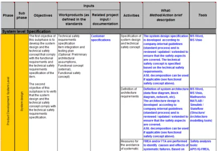
For the analysis of ISO 26262, all its clauses and requirements were translated to applicable practices and concrete activities to be performed by the industrial organizations. This means that the requirements of the standard were regrouped to activities that are described, assigned to different roles, and associated with their corresponding inputs, outputs and potential necessary tools. To perform this step, a spreadsheet, so-called “safety framework”, was developed, based on the previously outlined core parts of ISO 26262.
Figure 2 shows an excerpt of the safety framework. Note that the information contained in the spreadsheet is split into two different font types: The bold information evolves directly from
standard (e.g. columns “Phase”, “Sub-phase”, “Objectives”, “Work products”, “Activities”), whereas normal font is the interpretation and explanation that is developed in CESAR (e.g. columns “Related project input / documentation”,
“What Method / Action brief description”, “Tools”). For legibility reasons only an excerpt of the framework is presented here: For example, only the column “Inputs” is included. However, the same kind of information is provided in the complete safety framework for the outputs as well. Other information not visible in figure 2 is the assignment of roles. ISO 26262 makes no assumptions on roles within the safety life cycle. Therefore we introduce a role model, featuring all necessary roles from different technical domains, categorizing them to responsible and supporting roles, reducing the imminent risk of ambiguities.
After this first analysis focused on the automotive domain, the resulting safety framework is now being extended to other domains with the analysis of their applicable standards [1-4], [6-13]. Common properties and methods are identified, in order to broaden the framework’s spectrum.
Spreadsheets provide a great overview and carry valuable information. However it is difficult for engineers to derive further information from them: Relationships between activities, roles, and other process artefacts are hard to track. Moreover, the representation of workflows is hardly possible and element instances may not be created. Process modelling languages do provide these features, bringing the safety framework closer to its application.
4.2 The CESAR Approach to Process Modelling
The CESAR Practice Framework aims at finding new ways for the description and modelling of development processes and practices. The Software
and Systems Process Engineering Metamodel
(SPEM) [17] is used to define all necessary entities. Based on SPEM, the Eclipse Process Framework
(EPF) Composer [18] is used to realize the vision
of a versatile process framework, assisting process engineers and developers from the early beginning of safety related projects. The Automotive Safety
Framework is targeted at the needs of the
automotive domain and will integrate seamlessly to the practice framework, thanks to agreed modelling standards and concepts [19]. Starting with the previously described safety framework table, a mapping between the contained descriptions and the elements provided by the practice framework/EPF was established.
EPF supports various modelling concepts, allowing storing elements in packages and method
plugins. Most important concepts are affecting
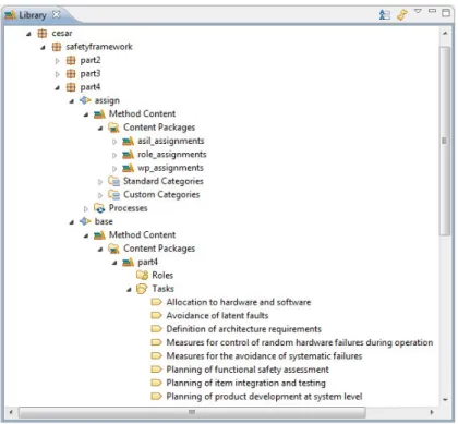
reusability and extensibility. These properties are preserved by creating base plugins, which hold generic definitions. These are extended later on by the creation of assign plugins. EPF’s variability feature was used to create relations between the elements of these two plugins. This modelling strategy was used to achieve a complete library of tasks, roles and work products, separated into different packages according to the core parts of ISO 26262. Furthermore, EPF has proven to be usable for the representation of quality related attributes [20], thus all ASIL related methods of ISO 26262 are represented as guidelines, organized in a hierarchy of packages. An overview of the resulting framework structure is shown in figure 3.
Another contribution to the safety process is the addition of work flows. The resulting library was used to arrange generic work flows, introducing sequences of tasks and activities.
Fig. 2. Process elements implementing the safety process in EPF
Finally, the resulting safety process library, the work flows and an appropriate process configuration are used to publish processes. In EPF, a publication typically consists of HTML (Hyper Text Markup Language) output files, including full graphics showing all dependencies between tasks, roles, work products and other artefacts. All information is available in XML (Extensible Markup Language) format as well, in order to support other means of automated process enactment. The RTP Desktop for example could use this type of process description for automated orchestration and enactment.
5 Requirements engineering
Safety is, besides of the functional aspect, one of the major areas in the field of requirements engineering of the CESAR Project. It has been approached from different perspectives like ontology based support, formalization support and different analysis techniques ranging from virtual safety integration tests to fault tree generation. Furthermore special requirements from safety standards like ISO 26262 have been considered and the developed methods adapted to suit the needs. Main principle is always the early detection of safety relevant requirements and early analysability even without having an architecture available. CESAR supports such black-box characterization of systems by enforcing that (i) requirements can be defined only in terms of the interfaces of these systems and (ii) that – once a (preliminary)
architecture is available – it can be checked against these requirements. Step (i) is supported by a formalization process that transforms natural language requirements into boilerplates and then uses the additional structure of these boilerplates to generate (instances of) requirement patterns for these. These patterns are equipped with a precise semantics (based on continuous-time traces of variables over discrete and continuous domains) fully removing ambiguity from requirement statements, and several checks are available to ensure – for instance – that they satisfy criterion (i) or that they are consistent. Step (ii) is supported by a virtual safety integration test that takes a preliminary architecture (with allocated requirements) and checks it against requirements resulting from step (i).
Beyond unambiguous requirements, CESAR provides means for context dependencies in requirement specification that are typical for safety-related standards like ARP 4754a (“A Safety Case
communicates a clear, comprehensible and defensible argument that a system is acceptably safe to operate in a particular context”, “The agreement should define the interface behaviours that are to be provided when an input is received”):
All requirements (and properties) come in the form of contracts consisting of promises expressing the needs for the system to be developed and
assumptions about the context where (and how) the
system is going to operate. For instance, the contract consisting of the assumption {CMD AS1
fail, CMD AS2 fail} does not occur and {CMD AS1 fail, VALID1 fail} does not occur and the promise {perm(CMD AS fail)} does not occur expresses the
expectation that a permanent failure on the CMD output (of a braking system controller) does not occur provided none of the two double failures in the assumption occur. The benefit of the patterns is that – although they have a lot of natural language elements – they come equipped with a formal semantics. For instance, the above assumption is equivalent to the following LTL formula:
¬(F (CMD AS1 fail) F (CMD AS2 fail)) ¬(F (CMD AS1 fail) F (VALID1 fail))
Thanks to these features it is possible to perform analyses on these patterns such as completeness and consistency, or analyses of fault propagation and impact on safety such as fault Tree Analysis.
6 Preliminary assessment and way forward
In addition to the system and process modelling activities described in section 3 and 4 as well as to the elaboration of safety oriented requirement engineering support as described in section 5, both being incorporated in the Reference Technology Platform, several use cases and scenarios have been defined by the industrial end-users so as to perform an assessment of the proposed technologies and tools.
At this stage, incremental assessment has been performed on two successive versions of the RTP, mainly to support the refinement of the requirements towards the final version. These experiments include pilot applications from all covered domains e.g., door management system or flight warning system (aeronautics), on recuperation and on power train control unit for hybrid vehicles, airbag control unit, brake by wire (automotive), safe controllers in industrial automation, on-board traffic management unit in railway, or FDIR (Failure Detection, Isolation and Reconfiguration) definition and validation and incremental safety assessment (space).
Though this assessment was performed in parallel to the actual incorporation of the innovations and their integration in the platform, and therefore mainly focussed on the assessment of basic techniques, methods and tools, it already provided important insights and better understanding of user expectations and remaining work.
It appeared in particular that some model-based safety languages and tools such as AltaRica are very powerful and well suited to the addressed problems [21]. However their specialisation may be a drawback and other modelling approaches and languages more widely used for system and software engineering such as AADL (Architecture Analysis and Design Language), UML (Unified Modelling Language) or SysML (Systems
Modelling language) could also be used, possibly with some adaptations and extensions [22]. We could for instance elaborate a prototype of an automatic transformation from space systems and FDIR AADL-based models (with specific adaptations and extensions for the purpose of the experiment) to timed automata so as to perform behavioural analysis and demonstration of properties on the temporal behaviour of the FDIR mechanisms [23]. These experiments and case studies confirm the validity and feasibility of the approaches investigated in the CESAR project, towards their integration in the final version of the Reference Technology Platform released at the end of 2011 for final assessment by the partners.
References
1 “Guidelines for Development of Civil Aircraft
and Systems”, EUROCAE ED-79A and SAE
Aerospace Recommended Practice ARP 4754A, 21/12/2010.
2 “Guidelines and methods for conducting the
safety assessment process on civil airborne systems and equipment”, EUROCAE ED-135
and SAE Aerospace Recommended Practice ARP 4761, 12/1996.
3 “Software considerations in airborne systems
and equipment certification”, EUROCAE
ED-12 and RTCA DO-178, issue B, 1/ED-12/1992. 4 “Design Assurance Guidance for Airborne
Electronic Hardware”, EUROCAE ED-80
and RTCA DO-254, 4/2000.
5 “Road vehicles – Functional safety”, International Standard ISO 26262:2011 (Parts 1-9), 11/2011.
6 “Functional safety of electrical/electronic/
programmable electronic safety-related
systems”, IEC 61508 Parts 1-7, Edition 2.0,
4/2010.
7 “Functional safety – Safety instrumented
systems for the process industry sector”, IEC
61511 Parts 1-3, Edition 1.0, 3/2003.
8 “Railway applications – The specification and
demonstration of reliability, availability,
maintainability and safety (RAMS)”,
CENELEC, EN 50126, 28/2/2007.
9 “Railway applications – Communications,
signalling and processing systems – Software for railway control and protection systems”,
CENELEC, EN 50128, 15/5/2001.
10 “Railway applications – Communications,
signalling and processing systems – Safety related electronic systems for signalling”,
11 “Space product assurance – Dependability”, European Cooperation for Space Standardisation, ECSS-Q-ST-30C, 6/3/2009. 12 “Space product assurance – Safety”, European
Cooperation for Space Standardisation, ECSS-Q-ST-40C, 6/3/2009.
13 “Space product assurance – Software product
assurance”, European Cooperation for Space
Standardisation, ECSS-Q-ST-80C, 6/32009. 14 P. Baufreton, JP. Blanquart, JL. Boulanger, H.
Delseny, JC. Derrien, J. Gassino, G. Ladier, E. Ledinot, M. Leeman, P. Quéré, B. Ricque, “Multi-domain comparison of safety
standards” in Proceedings of the 5th
International Conference on Embedded Real Time Software and Systems (ERTS2 2010), Toulouse, France, 19-21 May 2010.
15 “Recommended Practice for Architectural
Description of Software-Intensive Systems”,
ANSI/IEEE Std 1471, ISO/IEC 42010:2007 16 T. Peikenkamp, A. Cavallo, L. Valacca, E.
Boede, “Towards a Unified Model-Based
Safety Assessment”, Proceedings of
SAFECOMP, pp. 275-288, 2006.
17 Object Management Group, “Software and
Systems Process Engineering Meta-Model”,
v2.0, 2008.
18 P. Haumer, “Increasing Development Knowledge with EPFC”, Eclipse Review,
Spring 2006, 2006.
19 M. Cifaldi and F. Lanteri, “CESAR Practices
Framework – SPEM Mapping Guidelines”,
Draft 1, CESAR internal document, 2010. 20 Y. K. Chiam, M. Staples, and L. Zhu,
“Representing Quality Attribute Techniques
Using SPEM and EPF Composer”, EuroSPI
2009, 2009.
21 P.Bieber, JP.Blanquart, G.Durrieu, D.Lesens, J.Lucotte, F.Tardy, M.Turin, C.Seguin, E.Conquet, “Integration of formal fault
analysis in ASSERT: Case studies and lessons learnt” in Proceedings of the 4th International Conference on Embedded Real Time Software (ERTS 2008), Toulouse, France, 29/1-1/2/2008.
22 AE. Rugina, JP Blanquart, “Formal Methods
in Space Systems: Lessons Learnt”, Data
Systems in Aerospace, DASIA Conference, Budapest, Hungary, June 1-4, 2010.
23 JP Blanquart, P Valadeau, “Model-based
approaches for an improved FDIR
development and validation process”, Data
Systems in Aerospace, DASIA Conference, Malta, May 17-20, 2011.