HAL Id: cea-02338590
https://hal-cea.archives-ouvertes.fr/cea-02338590
Submitted on 21 Feb 2020
HAL is a multi-disciplinary open access archive for the deposit and dissemination of sci-entific research documents, whether they are pub-lished or not. The documents may come from teaching and research institutions in France or abroad, or from public or private research centers.
L’archive ouverte pluridisciplinaire HAL, est destinée au dépôt et à la diffusion de documents scientifiques de niveau recherche, publiés ou non, émanant des établissements d’enseignement et de recherche français ou étrangers, des laboratoires publics ou privés.
Status of the astrid gas power conversion system option
D. Plancq, L. Cachon, A. Remy, J. Quenaut, Y. Fasel, P. Gama, A. Dauphin,
L. Raquin
To cite this version:
D. Plancq, L. Cachon, A. Remy, J. Quenaut, Y. Fasel, et al.. Status of the astrid gas power conversion system option. GIF Symposium 2018 - The Generation IV International Forum, Oct 2018, Paris, France. �cea-02338590�
D. Plancq(1), L. Cachon (1), A.Remy(2), J.Quenaut(2), Yann Fasel(2), P.Gama(3), A. Dauphin(3),
L.Raquin(4)
(1) French Atomic Energy and Alternative Energies Commission (CEA), F- 13 108 Saint Paul Lez Durance, France (2) General Electric, Belfort, France
(3) Framatome, Lyon, France (4) NOX, Ivry sur Seine, France
Within the framework of the French 600 MWe Advanced Sodium Technological Reactor for Industrial Demonstration project, two options of Power Conversion System (PCS) were studied during the conceptual design phase (2010-2015):
- the use of a classical Rankine water-steam cycle, similar to the solution implemented in France in Phenix and Superphenix , but with the goal of greatly reducing the probability of occurrence and limiting the potential consequences of a sodium-water reaction; chosen as the reference for the ASTRID Plant Model during the conceptual design phase due its high level of maturity,
- the use of a Brayton gas cycle which has never been implemented in a Sodium Fast Reactor. Its application is mainly justified by safety and public acceptance considerations in inherently eliminating the sodium-water and sodium-water-air reaction risk existing with a Rankine cycle.
The ASTRID conceptual design phase period allowed to greatly increase the maturity level of a standalone Gas Power Conversion System option. It has been thus decided to lay during the 2016-2017 phase the ASTRID Gas PCS integration studies at the same level as that achieved by ASTRID Water based PCS at the end of 2015.
The 2016-2017 period, in which the Gas PCS has been integrated in the overall layout of the reactor, has allowed to better specify the technical and economic implications of the selection of gas PCS taking into account all the aspects of the integration of such an option. A well-documented comparison between the two systems is therefore facilitated.
This paper resumes progress in the integration of the Gas Power Conversion System in the ASTRID Reactor Plant Model. It describes the main characteristics defined particularly on the Balance of Plant (BOP), the turbomachinery, the Sodium Gas Heat Exchangers (SGHE) as well as expected performances, operability and safety analysis.
Introduction
The Sodium-cooled Fast Reactor (SFR) is one of the Generation IV reactor concepts selected to secure the nuclear fuel resources and to manage radioactive waste. Within the framework of the June 2006 act on the sustainable management of radioactive material and waste, the French Government asked CEA to conduct design studies for the Advanced Sodium Technological Reactor for Industrial Demonstration (ASTRID) project [1] in collaboration with industrial partners [2]. ASTRID is a project of an integrated technology prototype designed for industrial-scale demonstration of 4th-generation Sodium-cooled
Fast Reactor (SFR) safety and operation aiming at improving safety, operability and robustness
levels against external hazards compared with previous SFRs.
The pre-conceptual design phase – AVP1 conducted from mid-2010 to the end of 2012 – has been focusing on innovation and technological breakthroughs, while maintaining risk at an acceptable level. This phase was followed by the AVP2 conceptual design phase planned until the end of 2015 whose objectives were to focus on the design in order to finalize a coherent reactor outline and to finalize by December 2015 the Safety Option Report. The ASTRID conceptual design is based on a sodium-cooled pool reactor of 1500 MWth with an intermediate circuit in sodium generating about 600 MWe. Two Power Conversion Systems (PCS) were studied in parallel during the AVP2 conceptual design phase based on a Rankine steam cycle and a Brayton gas cycle.
Status of the ASTRID Gas Power Conversion System option
The steam PCS option is the most mature option. As it is the power conversion system for all SFRs up to now, it benefits from a large experience and tens of unit-operating years. For this option, conventional 180bar/500°C steam cycle conditions have been selected. Nevertheless, the always present sodium-water and sodium-water-air reactions risk is a strong design and operation constraint to be overcome.
The closed Brayton Gas PCS option is generally considered as the likely choice for High Temperature Reactors (HTR), as it provides at 800°C temperature range better cycle net efficiency than the best Rankine cycle. Application of Nitrogen closed Brayton cycle for a sodium cooled fast reactor in the 500°C temperature range is mainly justified for safety and acceptance considerations by inherently eliminating the sodium-water reaction risk existing in a Rankine cycle.
Despite the capabilities of the supercritical CO2 PCS to reach a high efficiency greater than 42% [3], the Nitrogen PCS option has been preferred due to its higher maturity. Nevertheless, SCO2 PCS remains an interesting option for commercial reactors, if Na/SCO2 reaction characterization will be done, N2 PCS being a first step towards operation feedback of a Brayton cycle.
During the ASTRID AVP2 phase from 2013 to 2015, a strong R&D effort was focused on the Gas PCS in order to increase its maturity level. This allowed to greatly increasing the maturity level of a standalone Gas Power Conversion System option [4].
It has been thus decided to lay during the 2016-2017 phase the ASTRID Gas PCS integration studies at the same level as that achieved by ASTRID Water based PCS at the end of 2015. The 2016-2017 phase, in which the Gas PCS is integrated in the overall layout of the reactor, allows to better specify the technical and economic implications of the selection of Gas PCS taking into account all the aspects of the integration of such an option. A well-documented comparison between the two systems is therefore facilitated.
This paper discusses progress in the integration of the Gas Power Conversion System in the Astrid Reactor Plant Model. It also describes the characteristics of the main systems particularly the turbomachinery, the Heat Exchangers
(Sodium/Gas, Gas/Gas and Gas/Water) and the Gas Inventory Management System.
ASTRID Gas Cycle performance
At the end of the AVP2 Phase (2013-2015), the reference cycle for the ASTRID Power Conversion System is a closed Brayton cycle in pure nitrogen at 180 bar (figure 1). The turbine and the compressors are placed on the same shaft line as the turbogenerator. Aiming at optimizing the cycle, the gas is cooled before the high pressure compressor inlet to limit the compression work and an economizer allows raising the temperature of the gas returning to the Sodium Gas Heat Exchangers (SGHE). The reference solution for the heat sink is a wet cooling tower. The closed cooling water system provides the cooling medium for the pre-coolers and coolers. The main boundary conditions for the thermodynamic gas cycle calculations are the following:
Thermal power delivered to the gas cycle: 1500 MWth
Sodium gas heat exchanger outlet temperature: 515°C
Sodium gas heat exchanger outlet pressure: 180 bar
Sodium gas heat exchanger inlet temperature: 310°C
Cooler outlet temperature: 27°C
The expected gross efficiency at the end of the AVP2 phase (2013-2015) is around 37.4 %, not taking into account cooling requirements, sodium pumps and auxiliary power. Main operation procedures of ASTRID gas power conversion system have been defined [5].
FIG.1. AVP2 Reference Brayton cycle
ASTRID Project Business Confidential Information, CEA and GE property designs
At the beginning of the phase 2016-2017, it has been asked to GE and CEA R&D to think about solutions to maximize the efficiency of the cycle. Different solutions were investigated (double intercooled cycle, reheated cycle, add CO2 to Nitrogen, ORC solutions…). The double intercooled cycle appeared as the most robust solution as it deals no impact on reactor side and no significant modifications on turbomachinery and Heat Exchangers thermal load (except an increase of 10% for the modular economizers). Thus, this solution has been embedded in the new configuration together with turbomachinery blade seals improvement.
FIG.2. New Reference Brayton cycle
ASTRID Project Business Confidential Information, CEA and GE property designs
The Heat Exchangers
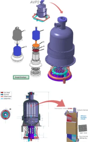
The Sodium Gas Heat Exchanger (SGHE) Eight Sodium Gas Heat Exchangers bring the thermal power to the Gas PCS. Due to their very
innovative design and operating conditions, The Sodium Gas Heat Exchanger (SGHE) is leading to a main technological challenge. The Sodium Gas heat exchanger is based on a compact plate heat exchanger technology investigated by the CEA [6] [7]. The SGHE concept is a component power unit of 190 MWth (2 components per secondary sodium loop), using a technology of plate assembly by high isostatic pressure diffusion bounding manufacturing process (HIP-DB) [7]. The principle of this design of SGHE is based on a component integrating 8 elementary modules of Compact Plate Heat Exchanger into a pressurized vessel which also plays the role of inlet manifold (Figure 3). These design options aim at:
limiting the impact of a failure of the exchanger module towards the outside, the external vessel constituting the second sodium containment barrier,
limiting the impact of a failure of the module on the secondary circuit: the maximal nitrogen leak section in the sodium is reduced, and the sodium manifolds are brought out the pressure vessel,
limiting the thermo-mechanical stresses: the pressure vessel structures are maintained at the heat exchanger low temperature, i.e. 310°C, and the plates are maintained in compression,
minimizing the sodium inventory in the components,
maximizing compactness and minimizing the pressure drop.
The significant weight of the pressure vessel and the fact that the internal sodium pipes are loaded by an external pressure are the main drawbacks of this concept.
Few mock-ups at small scale (40kW) have been manufactured and tested on the DIADEMO facility (CEA) in representative conditions [8]. The engineering of the SGHE general component was transferred to FRAMATOME in March 2016, CEA R&D pursuing design studies on exchange module because of its innovative nature [6]. A road map for the development, qualification and industrialization of SGHE was since developed in synergy between ANP and CEA R&D and two SGHE project reviews were performed. The principle to put the Compact Plate Heat Exchanger modules in a pressurized vessel, playing also a “header/gas pipes/safety
Status of the ASTRID Gas Power Conversion System option
containment” functions has been confirmed. The selection of a concept of a “on the floor” component has been made to authorize the disassembling of the upper part of the component.
FIG. 3: Sodium Gas Heat Exchanger
ASTRID Project Business Confidential Information, CEA and Framatome property designs
In parallel to this concept,Alternative SGHE design solutions are studied to reduce the total mass of the SGHE.
SGHE : Alternative concept The other exchangers
The new Brayton thermodynamic cycle with a double intercooled cycle leads to the choice of:
An economizer between the high pressure and low pressure lines of the cycle increasing the average operating temperature of the SGHE.
Three stage of compression with appropriated coolers to limit the compression work and the power input to the shaft-line. The operating conditions of these heat exchangers in terms of pressure and temperature are less severe than these imposed on sodium / gas exchangers. The economizer (also called recuperator) is a gas / gas exchanger between the high pressure and low pressure lines that passively cools the expanded gas from the turbine outlet and heat the recompressed gas before the SGHE to raise the average temperature of the heat source and thus improve the cycle efficiency. The pre-design studies carried out on this high power component show that only a modular technology of compact exchangers could be feasible for reasons of compactness and allowable mechanical load.
The pre-coolers and coolers are gas / water exchangers for cooling the compressor inlet gas to limit the compression work. They operate at the bottom pressure levels and temperature of the cycle (at pressures below 110 bar, temperatures below 100°C). The use of compact plate heat exchangers for these coolers leads to a gain in thermal compactness at least a factor of 10 compared to the shell and tube concepts. Furthermore, without grid, penalizing in terms of size and cost, it is not possible to implement exchangers based on plate&shell technology. Therefore, the modular technology of compact plate heat exchangers type should also withheld for gas cycle coolers.
The engineering of these exchangers of the tertiary gas cycle has been addressed by the CNIM Company since September 2016.
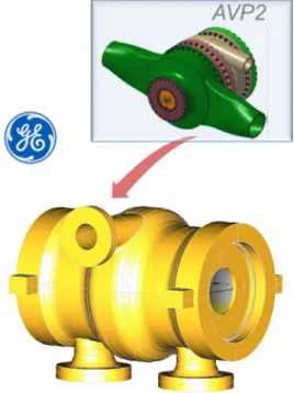
The turbomachinery
At the end of AVP2 Phase (2013-2015), the turbomachinery is based on 2 split flow axial turbines, one Low Pressure and one High Pressure radial Compressors on the same shaft line as the turbogenerator. The design of the turbomachinery has been pre-defined together with the main ancillary systems. All key technologies have references in the industry and the feasibility of the turbomachinery is confirmed.
The turbines
The driving machinery is a pair of multi-stage axial nitrogen turbine arranged in opposite direction (split-flow concept) to balance the axial thrust. An innovative design for the turbine inlet guiding the flow from the two incoming pipes to the blade area has been developed to minimize the head loss. A similar concept is used for the turbine outlet, which guides the flow leaving the last stage blade to the 2 outlet pipes (Figure 5). A barrel outer casing ensures tightness while minimizing thermal distortions. Several types of shaft-end seals such as mechanical seal, hydrodynamic seal, brush seal… have been investigated to minimize the shaft leakage. The bearings are conventional hydrodynamic tilt-pad bearings. These 2 elements are enclosed in the bearing housing.
A comparison between axial and radial technologies has been performed concluding that the axial technology was the most suitable for the turbine. Trade studies were performed between a single-flow turbine vs. split-flow turbine. Whilst the single-flow turbine aerodynamic efficiency was higher, the requirement for a balance piston to balance the turbine axial thrust makes the efficiency of the single-flow turbine at the same level of the flow turbine. In addition, a split-flow back-to-back turbine configuration reduces the risk thrust reversal during transient. This has also the benefit to lower blade gas bending loads due to shorter blades and twice the number of rows.
In the two shaft lines configuration, pipe lines connecting the turbine to the upstream and downstream components are limited to 4, with two inlet/outlet pipes per turbine casing. The reduction of the number of inlet / outlet piping simplifies penetrations and allows returning to
more conventional solutions compared to the one shaft line configuration.
Turbine casings are subjected to high internal pressure, especially at the turbine inlet. To limit casing ovalization causing leakage between turbine stages and a drop in performance, the current concept provides a double envelope with internal pressure balance.
Concerning the rotor, several construction technologies such as bolted rotors, monoblock rotor, welded rotor… have been investigated. Minimizing the mass/moment of inertia ratio was crucial to allow a better behavior when going through the turbine critical speed during speeding up/slowing down, and thus allowing the minimum radial clearances to be set. Thermal, thermomechanical and rotor dynamic analysis confirmed the feasibility of the rotor.
FIG. 5: Nitrogen turbine
ASTRID Project Business Confidential Information, CEA and GE property designs
During 2016, the GE team paid particular attention to on the consolidation of the turbomachinery concept, especially on the turbine design. Now the first concept is completed, and the team has sufficient insight to come back to those assumptions and ensure that they lead to the best concept. In parallel, GE has also investigated potential improvements proposed during the various GE internal design reviews and the ASTRID project Gas PCS expert review held at the end of AVP2. Independent concept studies using alternative tools have confirmed the feasibility of the turbomachinery and the anticipated performances (figure 6). A new design of turbine derived from steam/water turbine technology has been embedded. This design deals with a double flow turbine in a single outer casing is now possible. So far, the concept was based on 2 single-flow turbines, each having half the mass flow. The main advantages of the double flow are:
Status of the ASTRID Gas Power Conversion System option
The module is in internal thrust balance and transmits no effort to the shaft line.
There are only 2 joints instead of 4 and no joints at 180 bars
Total length is smaller
There is only one intake chamber, which then acts as a collector and equalizes the gas pressure from the 4 main pipes. This could potentially simplify operation with a secondary sodium loop unavailable.
However, a characteristic of the configuration of the dual flow turbine is that there are more penetrations in the outer shell (4 inlets and 4 outlets) than in the single flow turbine. Before confirming this design, the mechanical integrity of the envelope has to be verified by Finite Element analysis.
FIG. 6: Alternative Nitrogen turbine concept
ASTRID Project Business Confidential Information, CEA and GE property designs
Many aspects of the turbine design are already consolidated: axial technology, split-flow, hydrodynamic bearings, inner + outer casing construction, performance.
The compressors
Both axial and radial technologies were further analyzed. The radial technology has been maintained for its simplicity and robustness, but a multi-stage configuration has been chosen to maintain a good efficiency (figure 7). Split-flow compressors and face-to-face mounting single-flow compressors have been studied to minimize
residual axial thrust during all transients. Those options have been revisited in 2017 to take into account the new configuration with three compressors (HPC, IPC and LPC).
The new design still uses radial compressor technology from a proven family of wheels. On the other hand, the compressors are now double-flow, which minimizes the residual thrust of each component. The other advantage is that the transmitted torque of the blades on the shaft is lower (increasing number of wheels for the same total power), which makes it possible to mount the wheels on the shaft by tightening. The dual flow configuration also reduces the leakage rate at the shaft ends because both seals operate at the inlet pressure.
A good mechanical behavior of the wheels is expected even for maximum over-speed. Thermomechanical analysis of the staged pressure vessel shows that stress limits are widely observed. Only a few specific points are beyond the limits while remaining well below the allowable stress limit. To confirm the mechanical integrity of the pressure vessel, an elasto-plastic analysis was performed in accordance with the European Unfired Pressure Vessel Standard. This analysis has shown that all criteria were passed with a minimum lifetime greater than 10000 cycles for the most-strained areas of the casings.
ASTRID Project Business Confidential Information, CEA and GE property designs
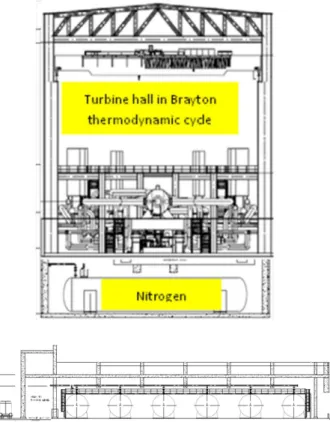
Gas Inventory Management System
Actual load of the shaft line is driven by the specific volume of the gas in the turbine. The Gas Inventory Management System allows the voiding and filling of the tertiary nitrogen circuit and allows management of the mass of gas in the tertiary circuit and thus the mean operating pressure according to the various operating conditions of the reactor. Note that rapid transients will primarily be managed by equipment bypasses. The Gas Inventory Management System, which is composed with 6 large gas storage vessels, 600 m3 under 50 bar each, is now
implemented on the ground floor of the turbine building, below the Brayton cycle equipment. In addition, a liquid nitrogen storage unit, and a set of nitrogen cylinders under 200 bar, allow to perform first filling and continuous make-up (to compensate leakage) of the Gas Inventory.
FIG. 8: Gas Inventory Management System
The General layout of the Gas PCS
During the AVP2 phase (2013-2015), a techno-economic analysis has been conducted on the ASTRID Gas PCS. A multiple parameters investigation concluded to an optimized configuration of the Gas PCS with two turbomachinery shaft lines in two separate turbine halls. This configuration led to a strong reduction of the number of gas lines and equipment, of the steel and nitrogen inventories (divided by a factor 2) and of the Gas Inventory Management System. In addition, the simplification of the gas piping layout allowed a better arrangement of the turbine hall with easier accessibility and maintainability. At the end of the ASTRID AVP2 phase, the selection of the concept of two 300 MWe Turbomachinery shaftlines in two separate turbine halls was confirmed and a first design of the main components was defined.
The new cycle configuration with a double intercooled cycle doesn’t change the number of Heat Exchangers but have consequence on their design.
Status of the ASTRID Gas Power Conversion System option
ASTRID Project Business Confidential Information, CEA and GE property designs
Integration of the Gas PCS in the ASTRID general model plant
The integration of the Gas PCS in the ASTRID reference configuration has been performed with the introduction of Sodium-Gas Heat Exchangers in the nuclear island and their connections with the Secondary Sodium Loops and the tertiary system. Several configurations of implantation of SGHE in Heat Exchanger buildings and plots of the Secondary Sodium Loops and tertiary lines have been studied in parallel with the turbine halls disposal on the general plant model in order to obtain optimal ergonomics of the buildings, of the buildings layout and of the gas piping layout. The selection of a lateral disposition of the turbine halls oriented to the south and a longitudinal disposition of SGHE in two lateral Heat Exchanger buildings has been made.
ASTRID Project Business Confidential Information, CEA and FRAMATOME property designs
Conclusions
Progress in the integration of the Gas Power Conversion System in the Astrid Reactor Plant Model has been described together with the characteristics of main systems particularly the turbomachinery, the Heat Exchangers (Sodium/Gas, Gas/Gas and Gas/Water) and the Gas Inventory Management System.
Those studies allow to better specifying the technical and economic implications of the selection of the Gas Power Conversion System taking into account all the aspects of the integration of such an option, enabling a well-documented comparison between Gas PCS and conventional Steam PCS.
REFERENCES
[1] F. GAUCHE “The French Prototype of 4th Generation Reactor: ASTRID”; Annual meeting on nuclear technology, Berlin, May 17&18th; (2011).
[2] J. ROUAULT et al. “ASTRID, The SFR GEN IV Technology Demonstrator Project: Where are we, where do we stand for?” Proceedings of ICAPP’15, Nice, France, May 03-06, (2015)
[3] H.S.PHAM “Mapping of the thermodynamic performance of the supercritical CO2 cycle and optimisation for a small modular reactor and a sodium-cooled fast reactor”; Energy 87 412-424 (2015)
[4] D. PLANCQ et al. “Status of studies on ASTRID gas power conversion system option”; Proceedings of ICAPP’16, San Francisco United-States, April 17-20, (2016)
[5] D. BARBIER et al. “Main operation procedures for ASTRID gas power conversion system”; Proceedings of International Conference on Fast Reactors and Related Fuel Cycles, Yekaterinburg, Russian Federation, (2017)
[6] D.PLANCQ et al. “Progress in ASTRID Sodium Gas Heat Exchanger Development”, Proceedings of International Conference on Fast Reactors and Related Fuel Cycles, Yekaterinburg, Russian Federation, (2017)
[7] L. CACHON et al. “Status of the Sodium Gas Heat Exchanger (SGHE) Development for the Nitrogen Power Conversion System Planned for the ASTRID SFR Prototype”, Proceedings of ICAPP 2015, Paper 15439, SFEN, Nice, France (2015).
[8] G. GAILLARD-GROLEAS et al., “the qualification process of simulation tools, components and systems within the frameworks of the ASTRID project – Description and examples” Proceedings of ICAPP’17, Fukui and Kyoto, Japan, (2017)
[9] In addition, D. PLANCQ et al., “Progress in the ASTRID Gas Power Conversion System development”. FR17 Paper IAEA-CN-245-285
[10] In addition, D. PLANCQ et al., “Progress in the ASTRID Sodium Gaz Heat Exchanger development”. FR17 Paper IAEA-CN-245-286