HAL Id: hal-01868419
https://hal.univ-lorraine.fr/hal-01868419
Submitted on 5 Sep 2018
HAL is a multi-disciplinary open access
archive for the deposit and dissemination of
sci-entific research documents, whether they are
pub-lished or not. The documents may come from
teaching and research institutions in France or
abroad, or from public or private research centers.
L’archive ouverte pluridisciplinaire HAL, est
destinée au dépôt et à la diffusion de documents
scientifiques de niveau recherche, publiés ou non,
émanant des établissements d’enseignement et de
recherche français ou étrangers, des laboratoires
publics ou privés.
To cite this version:
Sergei Zhgoon, Alexander Shvetsov, Sergei Sakharov, Omar Elmazria. High-Temperature SAW
Res-onator Sensors: Electrode Design Specifics. IEEE Transactions on Ultrasonics, Ferroelectrics and
Frequency Control, Institute of Electrical and Electronics Engineers, 2018, 65 (4), pp.657 - 664.
�10.1109/TUFFC.2018.2797093�. �hal-01868419�
Abstract— Surface acoustic wave (SAW) sensors are steadily
paving the way to wider application areas. Their main benefit consisting in the possibility of wireless interrogation with the radio frequency (RF) interrogation signal being the only energy source for the re-radiated signal. This feature is getting more and more attractive with the growing demand in monitoring multiple industrial objects difficult to access by wired sensors in harsh environments. Among such wider applications the possibility of making measurements of temperature, deformation, vibrations and some other parameters at temperatures in the range of 300-1000 °C look quite promising. This paper concentrates on specific features of the SAW resonator based sensors operation at this temperature range. High temperature influences the material choice and thus the properties of SAW resonators design peculiarities intended for use at high temperature. It is suggested that preferable designs should use synchronous resonators with relatively thick electrodes (10% of wavelength) based on Ir or Pt alloys while benefiting from the possibilities of specific designs that could reduce the negative impact of thick electrodes on the manufacturing in quantity. This solution benefits from lower resonance frequency scatter because of the automatic compensation of SAW velocity decrease due to electrode metallization ratio increase. This compensation originates from the resonance frequency increase that is related to the decrease of the Bragg bandwidth defined by the reflection. It is shown in modeling examples that the value of metallization ratio at which this compensation occurs is close to 65-70%.
Index Terms— Ultrasonic transducers, surface acoustic wave
SAW, resonator, high temperature sensor, Ir electrodes, metallization ratio.
I. INTRODUCTION
IRELESS interrogation of passive sensors with radio frequency (RF) interrogation signals is becoming more and more attractive. Monitoring of equipment operation in harsh environment or in otherwise inaccessible conditions especially for moving parts requires sensors that can survive these challenges. Among available choices surface acoustic wave (SAW) based sensors present many outstanding
Manuscript received August 19, 2017. This work was supported in part by the Ministry of Science and Education of the Russian Federation under grant 8.6108.2017/6.7.
S. Zhgoon is with the National Research University Moscow Power Engineering Institute, 111250, Moscow, Russia (e-mail: [email protected]).
A. Shvetsov is with the National Research University Moscow Power Engineering Institute, 111250, Moscow, Russia (e-mail: [email protected]).
properties. When correctly protected they can operate at temperatures in the range of 300-1000 °C and in conditions of high magnetic field, high electric field, ionizing radiation and aggressive chemical surrounding. SAW resonators and delay lines can be interrogated at a distance depending on the interrogation method, power and antenna designs and may vary from several centimeters to several meters. SAW sensors may be used in industrial applications and even serve as implantable devices in biological objects. The passive sensitive elements do not require batteries for their operation as they re-radiate a part of the received energy from the interrogating RF signal itself. They can be used for measuring pressure, deformation, torque, vibrations, temperature, magnetic and electric fields, concentration of chemicals in gases and liquids and in many other areas.
However, there are still many obstacles that prevent SAW sensors from taking a substantial part of the high temperature measurements market. Without more effort, they will not occupy their native market niches. Here we concentrate on specific features of high temperature SAW sensors and notably on the problems that arise in the choice of substrate and electrode materials and in the design concepts defined by high temperature survival and operation. We discuss below SAW resonators based sensors with the aim of reducing the size of the sensitive element.
Following our experience, the main present limitation of high temperature operational SAW resonators is the electrode material choice and the related design concerns that arise from increased thickness of the metal film. The thickness increase is dictated by the metal survival conditions at high temperature such as reactivity in air and vacuum with the substrate and atmosphere and recrystallization effects. Furthermore, the high resonator Q factors that define the measurement accuracy and the interrogation distance require as low as possible electrode resistance. These questions need to be addressed in a way that could give useful solutions to high temperature operation problems.
S. Sakharov is with the J.S.C. Fomos Materials, Moscow, 107023, Russia, (e-mail: [email protected]).
O. Elmazria is with the Institut Jean Lamour (IJL) UMR 7198, Université de Lorraine – C.N.R.S., Vandoeuvre les Nancy, France (e-mail: [email protected]).
High Temperature SAW Resonator Sensors:
Electrode Design Specifics
Sergei A. Zhgoon, Senior Member, IEEE, Alexander S. Shvetsov, Sergei A. Sakharov, and Omar
Elmazria, Senior Member, IEEE
A. Piezoelectric Materials
There is a proven range of single crystal materials for SAW devices used at ambient temperatures in mass-production such as LiTaO3, LiNbO3 and quartz. Their benefits are low
propagation loss, various values of electromechanical coupling allowing for very narrow to very wide passband operation, various temperature coefficients of frequency (TCF) ranging from 0 ppm/°C (with quadratic coefficient lower than 30 ppb/°C2) to above ±90 ppm/°C. These materials have some
limitations for operation at elevated temperatures. LiTaO3 has
a Curie temperature near 610 °C whilst the LiNbO3 Curie
temperature exceeds 1200 °C [1, 2]. However, the high electrical conductivity of congruent LiNbO3 complicates the
use of this material above 400 °C. The stochiometric LiNbO3 is
able to operate up to 600 °C [3]. Quartz is known to transform from α-phase into β-phase at 573°C [4]. Consequently, while it is possible and in some cases beneficial to use these materials below about 500 °C it is wise to consider other piezoelectric materials for use as sensors in a wider temperature range.
Among single crystals applicable at high temperatures langasite (also known as LGS, or lanthanum-gallium-silicate) and the family of chemically similar materials LGT (langatate), LGN (langanite), including multi-cation combinations such as CTGS have shown very promising and stable properties up to 1100 °C [5] – [9]. Historically langasite has been the most intensively used and studied material by the time of this publication preparation because of its larger scale production and accessibility. Interdigital transducers (IDT) on some useful langasite orientations become natural single phase unidirectional transducers (NSPUDT) because of the phase difference between transduction and reflection in the IDT. This feature is of particular interest in this work. Other materials of this family have shown to some extent similar behavior in the same temperature range. However, the use of substrates made with other materials of this family for SAW devices requires a selective approach to design and application because of their differences in acoustic wave properties related to different density and stiffness values.
Langasite is known to reversibly change its oxygen content at high temperature in different atmospheric conditions. This is followed by a change in the color of the crystal. None the less, the changes in SAW device properties are tolerable. The crystal growth related defects [10] and the temperature induced surface damage near electrodes on some substrate orientations [11] need additional care in substrate preparation and device design and fabrication. Other members of this family have not been studied to the same extent so far, and these problems may require further studies if they ever become candidates for commercially viable applications.
The AlPO4 and GaPO4 single crystals although showing
several very attractive features for operation even above 1000 °C, have not emerged from the research state yet, because of the difficulties in growing crystals of sufficiently large size for standard wafers fabrication. However, the recent progress in development of the technology especially for GaPO4 is very
The ReCOB single crystals have already been grown large enough to produce wafers up to 4” in diameter. Most materials in this family and notably YCOB and ErCOB do not undergo phase transitions up to about 1500 °C, together with other important features such as sufficiently high resistivity and relatively low variation of piezoelectric and dielectric constants [13] All these features make them very promising candidates as substrates for high temperature SAW sensors.
Thin piezoelectric films are interesting candidates for applications as high temperature devices and sensors. GaN and AlN thin films can be used at least up to 800 °C and they can be protected from atmospheric conditions by additional coatings [14], [15].
B. Packaging, Protection and Other Features Related to High Temperature Operation
It has been a complicated task to fabricate a reliable hermetically sealed package to encapsulate SAW sensors from damage at elevated temperatures. The package oozing into the die containing cavity may be enough to cause electrodes and substrate surface degradation. Additionally, package design requires development of very special preparation procedures prior to sealing [16].
Instead of using hermetically sealed packages the concept of packageless packaging is being explored [17], [18]. Fixing the die by organic glue is not possible for operation at high temperature. This problem has to be solved and inorganic adhesives need to be found for the mounting of deformation sensors on the measured objects.
The dependence of the SAW sensor electrical properties on the metallization ratio (M) with multiple dielectric coatings deposited over the electrodes is also very important.
C. Electrode Material Selection
The most common element of all RF SAW devices is the IDT that is usually made on the working surface of a piezoelectric substrate (or layer) by photolithographic means from a deposited thin film. The simplest single-phase IDT with metallization ratio 50% has alternating polarity electrodes; at the central frequency of the SAW device the width of the electrodes and the distance between them is close to a quarter-wavelength of the wave propagating in the IDT area. At frequencies between 100 MHz and 4 GHz with typical SAW velocities in the range 3000-4000 m/s the corresponding electrode width is in the range of 0.2-10 microns.
Modern ambient temperature front-end RF filters use relatively thick Al films, whose thickness reaches 10-12% of the IDT period, almost half the width of the electrode. Such electrode profiles are routinely obtained by photolithography; e-beam evaporation and lift-off are successfully applied for patterning. Further electrode thickness increase seems difficult because of precise patterning problems and because of the creation of spurious resonances. This approach requires additional studies for use in such structures.
For high temperature operation described in present publications the authors chose high melting temperature noble
metals that are most often based on pure Pt or Pt based alloys and compounds [19], or on Ir and its alloys including Ir-Rh alloys [20]. Some useful cases have been demonstrated but further studies are still required in this field.
However, it is clear from the published work [21] that the life span of a device with thin electrodes at elevated temperatures is limited. The thicker is the film used for electrodes the longer life can in principle be expected. This assumption has still to be proven, as thicker films have their own problems, such as suffering greater stress and related delamination, larger crystallites growing at elevated temperatures. All these problems are waiting to be taken care of. However, greater conductance of thicker electrodes is obvious and better device properties, such as a larger resonator Q-factor have already been demonstrated [22].
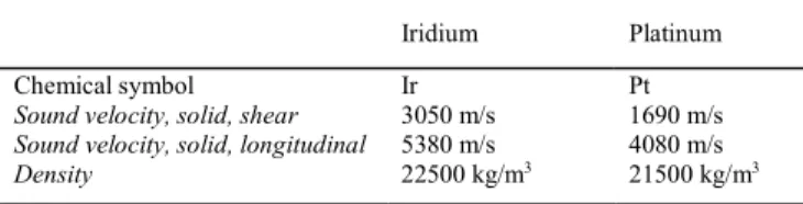
For these reasons, we will pay special attention to the use of thick electrodes made with dense materials. Both most common materials Pt and Ir have similar densities. However, they have distinctly different elastic and consequently acoustic wave properties. Following [23] the acoustic properties of Ir and Pt are illustrated in Table I.
TABLEI
ACOUSTIC PROPERTIES OF SOLID IRIDIUM AND PLATINUM
Iridium Platinum Chemical symbol Ir Pt
Sound velocity, solid, shear 3050 m/s 1690 m/s
Sound velocity, solid, longitudinal 5380 m/s 4080 m/s
Density 22500 kg/m3 21500 kg/m3
We concentrate below on Ir because it has a higher melting temperature and shows more durable operation [9]. But we do not reject Pt especially used in alloys.
III. PROPERTIES OF RESONATORS WITH SMALL-TO -MODERATE ELECTRODE THICKNESS
A synchronous resonator and an IDT itself without outer gratings can give two resonator-like responses when the reflection from the electrodes is sufficient and the reflection phase differs from zero. (We assume that the reflection phase equal to 0 corresponds to the reflection from infinitely thin conducting short-circuited strips). When the reflecting coefficient is strictly positive, the only maximum appears near the left edge of the reflection band. When it is strictly negative, the only maximum is close to the right edge. When the reflection phase is about 90° (as in NSPUDT built on specific orientations of piezoelectric crystal, notably on langasite (0º, 138.5º, 26.6º)) two almost identical maxima can appear at both edges of the reflection band. For intermediate values of the reflection phase between 0° and 180° both maxima are often observed with different heights. These heights depend on the electrode material, thickness and width. This behavior is intrinsic to an IDT with reflecting electrodes and it is a basic feature of synchronous SAW resonators, where outer gratings are added in order to increase the Q-factor of the resonances already defined by the IDT itself. The placement of the reflective gratings without breaking the periodicity of the
synchronous resonator structure as a whole ensures that the positions of the response maxima stay close to the edges of the reflecting band as illustrated in Fig. 1.
When the reflecting bandwidth is relatively small (Ir electrodes with thickness to IDT period ratio equal to 1.6% and pitch 5.99 microns), both maxima are clearly observed on a typical NSPUDT substrate on (0º, 138.5º, 26.6º) cut of langasite [7]. The dash lines mark the frequency corresponding to free surface SAW velocity with chosen wavelength. This synchronous resonator had 191 electrodes in the IDT, 50 electrodes in each short-circuited grating and the aperture of 300 µm. The pitch of the gratings was 2.974 µm and the IDT period was 5.948 µm.
In our recent measurements (Fig. 2) it is re-confirmed that thin Pt electrodes do not alter the SAW resonator properties excessively and both resonances are observable. A clear experimental evidence of usability of both resonances is shown in Fig. 2. It shows an example of a resonator response for langasite substrate with orientation (0°, 22°, 31°) and Pt electrodes of 100 and 200 nm. This synchronous resonator had 299 electrodes in the IDT, 250 electrodes in each short-circuited grating and the aperture of 500 µm. The pitch of the gratings was 6.584 µm and the IDT period was 13.168 µm.
It should be noticed that the right resonance frequency is almost independent on the thickness of the electrodes. This was attributed to the compensation of resonance frequency decrease related to the SAW velocity decrease with electrode thickness increase. The SAW velocity decrease was itself due to the mass loading with dense metals. However, the reflection from electrodes increases with electrode thickness. Subsequently, the Bragg bandwidth increases and the right resonance frequency
Fig. 2. Two-resonances measured response of a synchronous resonator with Pt electrodes on langasite (0°, 22°, 31°). The solid curve corresponds to a thinner Pt film and the dots – to a thicker Pt film.
-3 -2.5 -2 -1.5 -1 184.00 186.00 188.00 190.00 192.00 194.00 Lo g( R e( Y 11 )) Frequency, MHz
Fig. 1. Typical calculated logarithm of a synchronous resonator admittance magnitude for langasite (0º, 138.5º, 26.6º) with thin Ir electrodes (left), reflecting coefficient of the gratings (right).
0.3 0.5 0.7 0.9 1.1 1.3 1.5 420 430 440 450 460 470 Lo g( A b s( Y 11 )) Frequency, MHz 0 0.2 0.4 0.6 0.8 1 420 430 440 450 460 470 Re fl ec ti o n c o ef fi ci e n t ma gn it u d e Frequency, MHz
feature of the right resonance is very useful, as it helps to increase manufacturing yield thanks to this compensation effect. The stable position of the right resonance is obvious in Fig. 2.
For a resonator with thin electrodes there is one more commonly used design option with a single resonance in the response located approximately in the center of the Bragg band. For this resonator variant that was called “semisynchronous design” in [24] the gaps between the gratings and the IDT are different on both sides of the resonator. This option often helps to increase the resonator Q and to reduce the level of unwanted signal in the resonance vicinity such as the pulsations on the left of the left resonance in Fig. 2. However, “semisynchronous design” does not work for thick electrodes showing very large reflection.
IV. RESONATOR DESIGN OPTIONS FOR THICK IR ELECTRODES
When the reflection from electrodes is very large, the Bragg band increases considerably. Thus, the resonance frequency of the left peak, related to the left edge of the reflection band moves down while the right peak moves up. If the SAW velocity is not sufficiently slowed down by the electrode material, the peak at the right edge of the reflection band can move above the cut-off frequency defined by the lowest velocity bulk acoustic waves, thus the resonance maximum gets highly suppressed. It can still be found with special care in some structure responses, but it is already too low to be taken in consideration for serious applications.
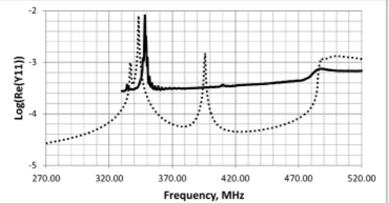
Present measurements made at room temperature of devices with thick Ir films (the relative thickness is equal to 8% of the IDT period) are analyzed in Fig. 3. The electrodes have the metallization ratio of about 40-50%. This test sample was designed as a semisynchronous resonator that was intended to operate at about 430 MHz with thin Ir. One of the gratings was placed in a position for synchronous resonator operation (without breaking the periodicity), while the other one was shifted by ¼ of the IDT period. The distance between the grating and the IDT was ½ of the IDT period on this side. The test resonator had 89 electrodes in the IDT, 300 electrodes in each short-circuited grating and the aperture of 280 µm. The pitch of the gratings was 2.995 µm and the IDT period was 5.99 µm. However, the measured resonator response is different from that initially expected. The solid curve in Fig. 3 illustrates
electrodes of the IDT determines a 60-70 MHz move of the peak frequency from the central frequency position (near 410 MHz) of a semisynchronous resonator. The central resonance that is observed at about 430 MHz in test resonators made with thin Ir is suppressed in this test sample having an 8% of the IDT period thick film. The remaining very small peak at about 410 MHz is still observable, but the strong peak near 350 MHz is no longer related to gratings positions, it is determined just by the frequency response of the IDT itself that is in turn determined by the left edge of the Bragg band related to the IDT periodic structure.
Fig. 3 shows some more peculiarities of this particular experimental device. There is a smaller peak at about 335 MHz on the left of the main peak. In fact, the thick Ir film has shifted the left edge of the Bragg band for the quasi-Rayleigh wave to this position. The Rayleigh wave was the main wave at small electrode thickness. Whilst the large peak at 350 MHz corresponds to the left edge of the Bragg band of the quasi-shear-horizontal (quasi-SH) wave, that became the dominant wave with a much stronger electromechanical coupling. In fact, when thick dense metals are used for fabrication of the electrodes on langasite with Euler angles (0, 138.5°, 26.6°) the initially existing on free surface quasi-Rayleigh wave becomes less pronounced, while a quasi-shear-horizontal wave that had initially a high velocity becomes dominant and non-leaky. These complex properties of multiple SAW modes on this particular cut of langasite with thick Pt electrodes are described in details in [25] and our simulations with FEM commercial software package Comsol Multiphysics® qualitatively agree
with this publication. The langasite constants used in this paper are taken from [26]. It is actually the wave with dominant shear-horizontal displacement that (following the modeling results) defines the main peak of the resonator response at 350 MHz in Fig. 3.
The simulation results for IDT period 5.99 µm are illustrated in Fig. 3 with dots. An infinite IDT structure is used in the model by applying antiperiodic conditions to a half period of the IDT containing a single electrode. This model usually describes relatively well the resonance frequencies observed in synchronous resonators while it does not describe completely the features of finite-length resonators. Here the metal thickness and metallization ratio variation were used for attempts to fit the experimental curve, as these parameters could not be measured with the required accuracy. We see that with these adjusted parameters we could more or less fit the positions of the main measured peak, of the small peak on the left as well as the shallow peak on the right. The modeled displacement profile at the frequency of the small peak corresponds to a quasi-Rayleigh wave, while the profiles about 340 MHz and 490 MHz correspond to quasi-shear-horizontal wave. The relatively small peak predicted in modeling at about 395 MHz has a modeled displacement profile corresponding to a quasi-Rayleigh wave and should be related to the right edge of the Bragg band for this wave. However, we do not observe any trace of it in the experimental curve. We suppose that it is completely hidden under the floor of the experimental curve
Fig. 3. Measured (solid) and simulated (dots) admittance for langasite with Euler angles (0, 138.5°, 26.6°), Ir thickness is 8% of the IDT period. Metallization ratio for the fitted curve is 40%.
-5 -4 -3 -2 270.00 320.00 370.00 420.00 470.00 520.00 Lo g( R e (Y1 1 )) Frequency, MHz
that we attribute to processing problems and to the use of semisynchronous resonator design that cannot be described in the model used.
As the acoustic wave velocity in Ir is relatively close to velocities in LGS family of materials, the central frequency does not drop too strongly with electrode thickness increase on most orientations. However, the acoustical impedance mismatch is very large and consequently the reflection from a single quarter wavelength electrode is also very large. The reflection bandwidth (Bragg bandwidth) of reflecting gratings becomes enormous, in an example calculation it reaches about 30% of the central frequency equal to 433 MHz. All this means that if a uniform IDT contains several electrodes with about 50% metallization ratio, it will reflect almost 100% of the wave energy at the central frequency. Thus, as shown in the experiment above a semisynchronous resonator design with additional gaps between the IDT and the gratings becomes non-operative as such resonance is highly attenuated inside the IDT itself. If the IDT is made with 2-5 electrodes, the features of semisynchronous resonator reappear in the response. However, such transducers are impractical because of too low admittance. Thus, the number of IDT electrodes of a more practical design exceeds several tens, and the IDT response dominates the response of a resonator.
It is explicitly pointed out in [25] that known COM-parameters models are unable to correctly describe the anomalous dispersion in gratings on this orientation of LGS with Pt electrode thickness exceeding 4%. The simulated curve in Fig. 3 shows that the potentially useful right resonance (observable in Fig. 2) shifts beyond the cut-off frequency and consequently becomes completely attenuated on this orientation of langasite. That is why this resonance could not appear in the measured curve.
A quite high value of Q-factor approaching 4000 was measured at room temperature in the device illustrated in Fig. 3 at 340 MHz after a 500 °C annealing treatment. However, as the resonance frequency depends very strongly on Ir film thickness the large frequency scatter becomes undesirable in high yield production, consequently the use of thick film of noble metals becomes less attractive. In some cases, the solution of the problem of yield can be found in using the right edge of the Bragg band (as discussed above for data shown in Fig. 2). That resonance is less sensitive to variations of electrode thickness. However, when the thickness is very large precise patterning becomes even more difficult than thickness control. There are several possible ways to explore in order to try to overcome these obstacles:
• First, we can try to find piezoelectric single crystal materials and orientations with more favorable properties of non-leaky wave propagation in gratings with thick Ir electrodes; or we can use electrodes made with a material that has a lower SAW velocity, such as Pt, and this can also help in designing the position of right resonance inside the frequency range of non-leaky SAW existence.
• Second, by reducing the SAW velocity and reflections with additional means such as dense dielectric coatings may shift the resonator response down, enough to ensure the
non-leaky wave propagation at a selected resonance. Such coatings, with careful selection may play a role of an additional protection of the electrodes from the harsh environment at high temperatures and even of a basic element of packageless packaging of the sensor. Film coating usually decreases the reflection and the Bragg bandwidth, so this effect may be beneficial as well.
• Third, we can try to increase the metallization ratio of the IDT electrodes and thus increase the average metal film thickness in order to slow down the wave of interest.
• Fourth, we can try to improve the left resonance and find the metallization ratio range where the influence of this particular parameter on the resonance frequency is reduced.
As the first suggestion seems obvious, the choice of orientations is one of the most important steps in SAW sensor operation. The second suggestion requires additional experiments; thus, we concentrate below on the last two suggestions.
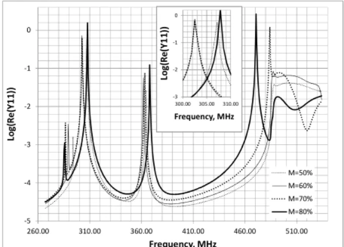
In fact, for some materials, and notably for Ir, it seems possible to use the right resonance. Fig. 4 shows that by choosing a larger metallization ratio, for thick Ir electrodes with the metallization ratio equal to 80% we can move the right resonance well below the cut-off area. Thus, we can ensure the possibility of obtaining low leakage loss at this resonance frequency.
The curves in Fig. 4 evidence that in langasite with Euler angles (0, 138.5°, 26.6°) many different types of waves exist with different properties when the electrode relative thickness reaches 10% of the IDT period. Displacement profiles at resonances for M = 80% are shown in Fig. 5. Here the choice of a useful wave is defined by the level of conductance at resonance.
The real part of the admittance frequency dependence for M = 80% shows a clean resonance close to 470 MHz. However, the hope of getting a low impact of electrode thickness/metallization ratio on the resonance frequency was not realized, as this peak shows even stronger frequency dependence on the metallization ratio than the resonance close to 308 MHz. When we compare the curves for M = 70% and
Fig. 4. Modeled dependence of an infinite IDT admittance on metallization ratio (M); the structure is made with Ir electrode thickness equal to 10% of the IDT period on langasite (0, 138.5°, 26.6°).
-5 -4 -3 -2 -1 0 260.00 310.00 360.00 410.00 460.00 510.00 Lo g( R e (Y1 1) ) Frequency, MHz M=50% M=60% M=70% M=80% -3 -2 -1 0 300.00 305.00 310.00 Lo g( R e( Y1 1) ) Frequency, MHz
bandwidth for this particular resonance has dropped significantly, or the wave type has changed and all this together with the influence of increased mass-loading acts in a way that this resonance loses its attractive features.
In Fig. 5 the profile at 285 MHz corresponds to the left resonance of a quasi-Rayleigh wave. The quasi-SH wave left resonance exists at 308 MHz. The quasi-Rayleigh wave right resonance is found again at 368 MHz, and another resonance at 470 MHz is related to the next mode with dominating vertical displacement.
A resonance at 368 MHz does show the wanted behavior but its amplitude is quite low compared to the 308 MHz value.
Fortunately, with the fourth possibility mentioned above, the behavior of the quasi-SH wave left resonance (close to 308 MHz) improves considerably. The inset in Fig. 4 shows that the resonances for M = 60% and 70% coincide. Thus, we obtain a range in metallization ratio M = 65% ± 5% with a relatively low sensitivity to electrode width variation when the thickness is fixed. In this range of M, the resonance frequency decrease with M growth (due to average thickness increase and related SAW velocity decrease with M) becomes compensated by the frequency increase on the left side of the Bragg band because of the reflection decrease.
This fact is especially important for resonators with thick electrodes made with dense metals. It should be noted, that by choosing M = 65% in this example (Fig. 4) we have been able to compensate the dependence of resonance frequency on the variation of M. This value of metallization ratio is close to the
with the increase of M now it rises with the increase of M. The dependency on M is quite small in the ±5% range. This range in Fig. 6 gives the value of frequency variation below 0.6 MHz when M changes from 65% to 60 % or to 70%, which is only 0.2% of the central frequency of this resonance. For M = 50% and 80% the frequency deviation is much higher and approaches about 6 MHz (2% of the central frequency) so that the dependence of resonance frequency on M in this range is a minimum.
This dependence on M may probably be extended to other thickness values with some correction in the M optimal value. However, this does not mean that we can obtain any compensation of frequency change related to thickness variation as it was for the resonance at the right edge of the Bragg band. Fig. 6 contains two curves related to only ±0.1% change in relative thickness and this gives an almost ±1.2 MHz of resonance frequency shift (about 0.4% of the central frequency) with a close to linear behavior. Fortunately, the thickness control in SAW device production is more precise than the patterning of relatively thick films. In any case frequency trimming is also feasible and common. Thus, the possibility of obtaining lower scatter related to the patterning process is a promising way of yield improvement especially important for relatively thick electrodes.
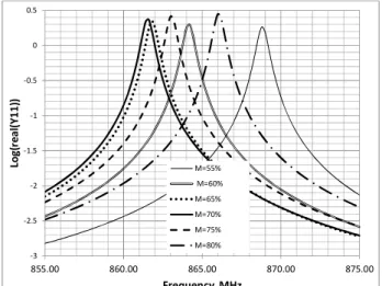
In Fig. 7 an example of modeled behavior of thick Ir electrodes on AlN piezoelectric substrate is given. The modeling was performed in Comsol Multiphysics® with
built-in AlN material constants for an IDT period of 4 microns and relative thickness of Ir electrodes equal to 10% of the IDT period. The substrate orientation was Z-X. In comparison with the results shown in Fig. 6 there is a small shift of the metallization ratio optimal value from 65% in the direction closer to 70% while the dependence of resonance frequency appears to be quite similar. Here in the 15% range of M (60% < M < 75%), the frequency deviation does not exceed 0.3%. In fact, this behavior of the resonance on the left side of the Bragg band may seem to be universal for most substrates. However,
285 MHz 308 MHz 368 MHz 470 MHz Fig. 5. Displacement profiles at resonances obtained for M = 80%.
Fig. 6. Details of the modeled dependence of an infinite IDT admittance on film thickness and on metallization ratio; the structure is made with Ir electrode thickness (H) equal to 10% of the IDT period on langasite (0, 138.5°, 26.6°). -2.5 -2 -1.5 -1 -0.5 0 300.50 301.50 302.50 303.50 Lo g( R e (Y1 1 )) Frequency, MHz H=10% M=60% H=10% M=65% H=9.9% M=65% H=10.1% M=65% H=10% M=70%
Fig. 7. Details of the modeled dependence of an infinite IDT admittance on metallization ratio; the structure is made with Ir electrode thickness equal to 10% of the IDT period on AlN substrate.
-3 -2.5 -2 -1.5 -1 -0.5 0 0.5 855.00 860.00 865.00 870.00 875.00 Lo g( re al (Y 1 1 )) Frequency, MHz M=55% M=60% M=65% M=70% M=75% M=80%
this is not true for any substrate and any orientation and such possibility has to be verified for every particular substrate and orientation.
Our interest in this work is focused on Ir with relative thickness near 10% of the IDT period. However, the change of electrode material and of the thickness may introduce more differences. Consequently, these features deserve more study.
V. CONCLUSION
There are still many challenges to answer before high temperature SAW sensors may claim a respectable application scale. Some of the material problems have already been solved and new substrate materials promise better and better performance. The studies of problems related to electrodes and structure protection are also being addressed. The possibility of ameliorating the problems of manufacturing accuracy related to the yield when fabricating resonator structures with Ir electrode relative thickness reaching up to 10% of the IDT period by choosing the metallization ratio near 65% is one of the steps towards wider application and higher measurements’ accuracy. ACKNOWLEDGMENT
Advice of N. Naumenko on LGS acoustic properties and proofreading of the manuscript by R. L. James are gratefully appreciated.
REFERENCES
[1] G. A. Smolenskii, N. N. Krainik, N. P. Khuchua, V. V. Zhdanova, and I. E. Mylnikova, “The Curie Temperature of LiNbO3,” Phys. Status Solidi, vol. 13, no. 2, pp. 309–314, 1966.
[2] J. I. Kushibiki, Y. Ohashi, and N. Mishima, “Calibration of curie temperatures for LiTaO3 single crystals by the LFB ultrasonic material characterization system,” IEEE Trans. Ultrason., Ferroelectr. Freq. Control, vol. 50, no. 5. pp. 544–552, 2003.
[3] T. Aubert et al., “First investigations on stoichiometric lithium niobate as piezoelectric substrate for high-temperature surface acoustic waves applications,” in 2017 IEEE Sensors Symp., pp. 1-3.
[4] C. Koike et al., “Infrared spectra of silica polymorphs,” in Proceedings of Science, 2013.
[5] M. P. Da Cunha, R. J. Lad, T. Moonlight, G. Bernhardt, and D. J. Frankel, “High temperature stability of langasite surface acoustic wave devices,” 2008 IEEE Ultrason. Symp., pp. 205–208.
[6] S. Sakharov et al., “Investigation of the CTGS single crystals potential for high temperature SAW devices,” in 2013 IEEE Int. Ultrason. Symp.,. pp. 1085–1088.
[7] S. Sakharov et al., “Theoretical and experimental investigation of langasite as material for wireless high temperature SAW sensors,” 2010 IEEE Int. Ultrason. Symp., pp. 535–538, 2010.
[8] T. Aubert and O. Elmazria, “Stability of langasite regarding SAW applications above 800 °C in air atmosphere,” in 2012 IEEE Int. Ultrason. Symp., , pp. 2098–2101.
[9] T. Aubert, J. Bardong, O. Elmazria, G. Bruckner, and B. Assouar, “Iridium interdigital transducers for high-temperature surface acoustic wave applications,” IEEE Trans. Ultrason. Ferroelectr. Freq. Control, vol. 59, no. 2, pp. 194–197, 2012.
[10] R. Fachberger, E. Riha, E. Born, W. Ruile, P. Pongratz, and S. Kronholz, “Homogeneity of Langasite and Langatate wafers,” 2002 IEEE Int. Freq. Control Symp., vol. 1. pp. 311–319.
[11] J. Bardong, G. Bruckner, M. Kraft, and R. Fachberger, “Influence of packaging atmospheres on the durability of high-temperature SAW sensors,” Proceedings – 2009 IEEE Ultrason. Symp., pp. 1680–1683. [12] O. Cambon and J. Haines, “Hydrothermal Crystal Growth of Piezoelectric
α-Quartz Phase of AO2 (A = Ge, Si) and MXO4 (M = Al, Ga, Fe and P = P, As): A Historical Overview,” Crystals, vol. 7, no. 2. p. 38, 2017.
[13] F. Yu et al., “Dielectric and electromechanical properties of rare earth calcium oxyborate piezoelectric crystals at high temperatures,” IEEE Trans. Ultrason. Ferroelectr. Freq. Control, vol. 58, no. 4, pp. 868–873, 2011.
[14] O. Legrani et al., “AlN/IDT/AlN/Sapphire SAW Heterostructure for High-Temperature Applications,” IEEE Transactions on Ultrasonics, Ferroelectrics, and Frequency Control, vol. 63, no. 6. pp. 898–906, 2016. [15] T. Aubert et al., “In situ high-temperature characterization of AlN-based surface acoustic wave devices,” J. Appl. Phys., vol. 114, no. 1, p. 14505, 2013.
[16] B. François, J. M. Friedt, G. Martin, and S. Ballandras, “High temperature packaging for surface acoustic wave transducers acting as passive wireless sensors,” Sensors Actuators, A Phys., vol. 224, pp. 6–13, 2015. [17] O. Legrani, O. Elmazria, S. Zhgoon, P. Pigeat, and A. Bartasyte,
“Packageless AlN/ZnO/Si structure for SAW devices applications,” IEEE Sens. J., vol. 13, no. 2, pp. 487–491, 2013.
[18] S. Zhgoon et al., “Potential of Al2O3/GaN/Sapphire layered structure for high temperature SAW sensors,” in Proceedings of the 2015 Symp. on Piezoelectricity, Acoustic Waves and Device Applications, SPAWDA 2015, pp. 106–110.
[19] M. Pereira Da Cunha, A. Maskay, R. J. Lad, T. Coyle, and G. Harkay, “Langasite 2.45 GHz ISM band SAW resonator for harsh environment wireless applications,” in 2016 IEEE Int. Ultrason. Symp., pp. 595-598. [20] A. Taguett et al., “Comparison between Ir, Ir0.85Rh0.15and Ir0.7Rh0.3
thin films as electrodes for surface acoustic waves applications above 800 °C in air atmosphere,” Sensors Actuators, A Phys., vol. 266, pp. 211–218, 2017.
[21] S. Sakharov et al., “Optimization of wafer orientation and electrode materials for LGS high-temperature SAW sensors,” in 2012 IEEE Int. Ultrason. Symp., pp. 1525–1528.
[22] S. Sakharov et al., “Technological process and resonator design optimization of Ir/LGS high temperature SAW devices,” in 2014 IEEE Int. Ultrason. Symp., pp. 377–380.
[23] W. Martienssen and H. Warlimont, Springer Handbook of condensed Matter and Materials Data, vol. 1. 2005.
[24] D. P. Morgan, S. Zhgoon, and A. Shvetsov, “One-port SAW resonators using natural SPUDT substrates,” IEEE Trans. Ultrason. Ferroelectr. Freq. Control, vol. 54, no. 10, pp. 1936–1942, 2007.
[25] N. Naumenko, “Anomalous dispersion of SAW in platinum grating on langasite with Euler angles (0, 138.5, 26.6),” in 2014 IEEE Ultrason. Symp., pp. 543–546.
[26] S. Sakharov, P. Senushencov, A. Medvedev, and Y. Pisarevsky, “New data on temperature stabilyty and acoustical losses of langasite crystals,” in 1995 IEEE Int. Freq. Control Symp., pp. 647–652.
Sergei A. Zhgoon (A’96–M’96– SM’09) graduated from Moscow Power Engineering Institute (MPEI) in 1974 (present name: National Research University MPEI). He received his Ph.D. degree from the same university in 1979. In 1986, he was awarded the degree of Senior Research Fellow. Since 1974 he has been permanently working at the Department of Radio Engineering Fundamentals in MPEI. Since 1983 he has been the head of the laboratory in this department. His present research interests are in surface acoustic wave (SAW) devices 1975. His main areas of expertise presently include all aspect of microwave acoustics device fundamentals, design of SAW/BAW filters, resonators, RF ID tags and their preparation techniques, thin film deposition and patterning, advanced chip-scale and wafer-scale packaging with MEMS-like techniques, surface acoustic wave propagation in multilayered and strained media, and SAW sensors based on these phenomena. He has co-authored over 180 publications and about 20 patents. He has supervised over 20 M.S. and 4 Ph.D. students in MPEI.
B.S. degree in 2004, the M.S. degree in 2011 and the PhD degree in 2017 from MPEI in radio engineering. He has been working in the SAW devices research group in Moscow Power Engineering Institute (present name: National Research University MPEI) since 2001. His scientific interests currently involve effects of acoustic wave propagation and properties of piezoelectric transducers applied to signal processing devices and sensors. This work is reflected in over 35 technical papers published from 2003 to 2017
Sergey A. Sakharov graduated from Moscow Institute of Steel and Alloys (MISiS), specialty - crystallophysics.
Mr Sakharov has been working in the sphere of piezoengineering since 1985, R&D establishment “Fonon“– Head of the laboratory for the development of monolithic filters on strong piezoelectric
which produces piezoelectric crystals, develops sensitive elements and wafers for SAW applications. He is now Deputy General Director of JSC Fomos Materials. He has more than 50 publications and 12 patents for piezoelectric theme.
Omar Elmazria (M’2001–SM’16)
received his Ph.D. degree in electronics from Metz University, France, in 1996 and he joined the University of Nancy I as associate Professor of electronic and communication systems in 1997 and as a full Professor in 2003. Was the Head of the Micro and Nanosystems Group within the Institut Jean Lamour. His current research focus on layered structures based surface acoustic waves (SAW) devices for communication systems and sensing applications. He co-authored more than150 papers in refereed international journals and in proceeding of international conferences. In 2017, he received the medal of URSI-France (International Union of Radio Science).