HAL Id: hal-02354352
https://hal.archives-ouvertes.fr/hal-02354352
Submitted on 25 Nov 2019HAL is a multi-disciplinary open access archive for the deposit and dissemination of sci-entific research documents, whether they are pub-lished or not. The documents may come from teaching and research institutions in France or abroad, or from public or private research centers.
L’archive ouverte pluridisciplinaire HAL, est destinée au dépôt et à la diffusion de documents scientifiques de niveau recherche, publiés ou non, émanant des établissements d’enseignement et de recherche français ou étrangers, des laboratoires publics ou privés.
Electrochemical ageing study of mixed
lanthanum/praseodymium nickelates La2-PrNiO4+δ as
oxygen electrodes for solid oxide fuel or electrolysis cells
Vaibhav Vibhu, Aurelien Flura, Aline Rougier, Clément Nicollet, Sébastien
Fourcade, Teresa Hungría, Jean-Claude Grenier, Jean-Marc. Bassat
To cite this version:
Vaibhav Vibhu, Aurelien Flura, Aline Rougier, Clément Nicollet, Sébastien Fourcade, et al.. Elec-trochemical ageing study of mixed lanthanum/praseodymium nickelates La2-PrNiO4+δ as oxygen electrodes for solid oxide fuel or electrolysis cells. Journal of Energy Chemistry, Elsevier, 2020, 46, pp.62-70. �10.1016/j.jechem.2019.10.012�. �hal-02354352�
1
Electrochemical ageing study of mixed
lanthanum/praseodymium nickelates La
2-xPr
xNiO
4+δas
oxygen electrodes for solid oxide fuel or electrolysis cells
Vaibhav Vibhua, Aurélien Fluraa, Aline Rougiera, Clément Nicolleta, Sébastien Fourcadea,
Teresa Hungriab, Jean-Claude Greniera, Jean-Marc Bassata,*
aCNRS, Univ. Bordeaux, Bordeaux INP, ICMCB, UMR 5026, F-33600 Pessac Cedex, France b Centre de Microcaractérisation Raimond CASTAING, Université de Toulouse, CNRS, UT3 – Paul Sabatier, INP, INSA, Espace Clément Ader, 3 rue Caroline Aigle, 31400 TOULOUSE France
*Corresponding author. E-mail address: jean-marc.bassat@icmcb.cnrs.fr (J.-M. Bassat).
Abstract: The chemical and electrochemical stability of lanthanide nickelates La2NiO4+δ (LNO),
Pr2NiO4+δ (PNO) and their mixed compounds La2-xPrxNiO4+δ (LPNOs) with x = 0.5, 1 or 1.5 is
reported. The aim is to promote these materials as efficient electrodes for solid oxide fuel cell
(SOFC) and/or solid oxide electrolysis cell (SOEC). La2NiO4+δ and La1.5Pr0.5NiO4+δ compounds are
chemically very stable as powders over one month in the temperature range 600 − 800 °C, while
the other materials rich in praseodymium progressively decompose into various perovskite-deriving
components with additional Pr6O11. Despite their uneven properties, all these materials are quite
efficient and sustainable as electrodes on top of gadolinium doped ceria (GDCBL) // yttrium doped
zirconia (8YSZ) electrolyte, for one month at 700 °C without polarization. Under polarization (300
mA∙cm-2), the electrochemical performances of LNO, PNO and La
1.5Pr0.5NiO4+δ (LP5NO) quickly
degrade in SOFC mode, i.e. for the oxygen reduction reaction, while they show durability in SOEC
mode, i.e. for the oxide oxidation reaction.
2
1. Introduction
The reduction of the operating temperature of Solid Oxide Fuel Cells (SOFCs) or Solid
Oxide Electrolysis Cells (SOECs) is a critical challenge for their commercialization. Presently, the
objective is to decrease it down to the intermediate range (600 – 700 °C), with the aim to reduce
the cost by using stainless steel instead of ceramics as interconnects for instance, as well as to
improve their long-term cell durability. In this scope, the study of the long-term stability of the
SOFC ceramic components is paramount [1, 2]. The cell degradation is generally due to various
phenomena such as, i) a grain coarsening, particle smoothing/rounding and/or phase instability
occurring at the electrodes, ii) an interfacial segregation, impurities accumulation and cationic
inter-diffusions occurring at the interfaces between the different layers of the cell.
As the oxygen electrode contributes to a large extent to the cell polarization resistance, Rp, a lot of
work available in the literature aims to design materials with MIEC properties [3-6] suitable for
both SOFCs and SOECs. In this respect oxygen deficient perovskites based materials have been
extensively studied e.g. La1−xSrxCo1−yFeyO3−δ (LSCF) [7-10], La1−xSrxCoO3−δ (LSC) [11-13],
Ba1−xSrxCo1−yFeyO3−δ (BSCF) [14, 15]. However these La, Sr-cobaltites based oxygen electrode
materials have inherent disadvantages: (a) a Sr-segregation leading to the formation of SrZrO3
insulating phase [16-19]; (b) high values of thermal expansion coefficients [4, 5] and (c) a
crystallographic phase transition from rhombohedral to cubic [20], leading to a degradation of the
cell performances. Ba, Sr-cobaltites based oxygen materials also exhibit a poor chemical stability
[21].
More recently, another kind of MIEC oxides having the K2NiF4-type layered structure and showing
3
has been reported as oxygen electrode materials. For example, rare earth nickelates Ln2NiO4+δ (Ln
= La or Pr) have been studied from long time [22-24]. Indeed, these compounds show good
electronic conductivity [25, 26] and high diffusivity of oxide ions[27-29]. Then, due to their large
anionic bulk diffusion (D*) as well as surface exchange coefficients (k*), combined with good
electrical conductivity and thermal expansion properties matching with those of electrolyte
materials, they have been extensively used as oxygen electrodes in Solid Oxide Cells [30-35].
Among these nickelates, PNO shows the lowest polarization resistance (Rp) [32] while LNO is
highly chemically stable [36]. In a recent study, lanthanum praseodymium nickelates La
2-xPrxNiO4+δ (0.0 ≤ x ≤ 2.0) (hereafter labeled LPNO) were considered to find the best compromise
between high electrochemical performance and long-term chemical stability [37]. The
electrochemical performance in these mixed La, nickelates is increased with increasing
Pr-content. For instance, a Rp value of 0.93 Ω·cm² is achieved at 600 °C for LNO/GDC/8YSZ
symmetrical cell while after substitution of La by Pr, the Rp values decrease down to 0.37, 0.29,
0.23 and 0.15 Ω·cm² for La1.5Pr0.5NiO4+δ, LaPrNiO4+δ, La0.5Pr1.5NiO4+δ and PNO, respectively.
Regarding single cell performances, the PNO electrode containing single cell shows better behavior
than LSCF electrode deposited on the same Ni-YSZ/YSZ/GDC support, in both SOFC and SOEC
mode. The corresponding LNO single cell has lower performance than LSCF cell in SOFC mode
while almost comparable behavior than LSCF in SOEC mode [38]. Kim et al. have also reported
similar results for LNO [39].
The next step is to prove the durability of these nickelates based cells over the long term. In this
paper, ageing of LNO, PNO and LPNO without polarization for one month or under idc = 300
mA∙cm-2 for two-and-a-half month is reported. In the latter case, the results of the ageing are given
for the electrode operating in SOFC mode, i.e. the reduction of O2, or in high-temperature
4
The degradation occurring during the ageing is analysed and discussed based on X-ray diffraction
and FIB-SEM analysis.
2. Experimental
2.1. Powder preparation
Five compositions of La2-xPrxNiO4+δ, with x = 0.0 (LNO), 0.5 (LP5NO), 1.0 (LP10NO), 1.5
(LP15NO), or 2.0 (PNO) were synthesized using the citrate-nitrate route (modified Pechini method)
[40]. The corresponding precursors were Pr6O11 (Aldrich chem, 99.9%), La2O3 (Strem Chemical,
99.99%) and Ni(NO3)2·6H2O (Acros Organics, 99%). The final annealing was performed at 1200
°C for 12 h under air, leading to single and well-crystallized phases for all compositions. The
resulting powders were attrited using zirconia balls and ethanol for 4 h to reach an average particle
size of about 0.6 µm. More details about the powder preparation are given in ref. [37].
2.2.Cell manufacturing
Symmetrical half-cells (LPNO electrode//GDCBL//8YSZ) were shaped for the electrochemical
studies. Terpineol-based inks were prepared for the different LPNO phases and the 20 at.%
gadolinium doped ceria barrier layer (GDCBL). First, GDCBL layers (thickness ≈ 3 µm) were
symmetrically screen printed on both sides of dense 8YSZ pellets (diameter ≈ 18 mm and thickness
≈ 1.2 mm), then sintered at 1300 °C, for 1 h, in air. The nickelate layers (thickness ≈ 10–15 µm, ~ 15 mm) were afterwards symmetrically screen printed and sintered at 1150 °C, for 1 h, under N2
atmosphere (pO2 ≈ 10-4 atm), then re-oxidized under air at 800 °C in the set-up. These sintering
temperatures were previously optimized to obtain a controlled homogeneous porous electrode
microstructure corresponding to the lowest polarization resistance Rp values recorded for these
5
2.3.Electrochemical characterization
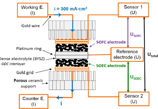
Electrochemical measurements, as well as ageing experiments, were performed using symmetrical
half-cells as described in Fig. 1. Two geometries were considered:
(i) a symmetric two electrodes system for experiments without polarization; in that case, only the
potential Utotal is measured to obtain the impedance diagrams.
(ii) a so-called “three-electrode” system for the ageing under polarization (idc = 300 mA∙cm-2): a
reference electrode is needed in that case, which is a painted ring of platinum set all around the
edge of the thick 8YSZ electrolyte ceramic, in a region of stable potential [42-44]. Under a given
polarization, the electrodes differently behave depending on the current flow going through them:
then, one electrode works in SOFC mode characterized by USOFC, the second one works in SOEC
mode characterized by USOEC, the whole cell being characterized using Utotal.
6
Current collectors were made of gold grids (1024 meshes per cm2). All the EIS measurements,
either on as-prepared or aged cells, were always carried out in air, in the temperature range 500–
800 °C. The impedance diagrams were recorded at steady state (idc = 0 mA∙cm-2), under
potentiostatic control with 50 mV ac amplitude, from 106 Hz down to 10-1 Hz, using a frequency
response analyzer Autolab FRA2, coupled with a potentiostat/galvanostat PGSTAT 302N. For the
ageing study under polarization, EIS measurements were performed every few hours; the dc current
was stopped and the cell stabilized for 10 min, prior to the EIS measurements. The complex
impedance diagrams were fitted using Zview2® (Scribner associates, inc.). The polarization
resistance Rp was calculated from the difference between the low (LF) and the high frequencies
(HF) diagram intercepts with the Z′-axis of the Nyquist representation, and the Rs (series resistance)
values were obtained by taking the high-frequency intercept on Z′-axis.
2.4. XRD analyses
All the X-ray diffraction analyses for the LPNOs raw powders and the thermally aged powders
were performed using a PAN-analytical X’pert MPD diffractometer with Cu-Kα (λ = 0.15418 nm)
incident radiation. The ageing of the powders was conducted as follows: three green pellets (about
60% density) were first prepared and then left in air, for one month, at 800 °C (the EIS measurement
temperature) and at 700 °C and 600 °C , before being crushed into powders prior to the XRD
characterization.
The top surfaces of the LNPO electrodes screen-printed on GDCBL//8YSZ were also analyzed, after
the ageing processes at 700 °C under idc = 300 mA∙cm-2.
7
Cross sections of aged cells were prepared by focused ion beam milling; subsequent SEM images
and elemental microanalyses were recorded using a Dual Beam SEM / FIB FEI Helios
600i equipped with an EDX Oxford Instruments analyser Aztec Advanced equipped with a SDD
detector.
3. Results
Before studying the ageing of the materials as electrode on GDCBL//8YSZ, it was necessary to
determine their chemical stability as raw powder.
3.1. Chemical stability of LNO, PNO and LPNOs for one month at T = 600 °C, 700 °C or 800 °C
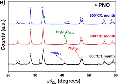
The short-term chemical stability of LNO (x = 0) and PNO (x = 1) has been previously reported by
our group [45]. In the current study, we verified that LNO is chemically stable up to one month,
whatever the temperature. PNO decomposes at 600 °C into Pr6O11 and PrNiO3-, and at 700 °C and
800 °C with additional Pr4Ni3O10+. This behaviour agrees with another of our recent article[46]
reporting that PrNiO3- decomposes into Pr4Ni3O10+ at T ≥ 700 °C in air.
20 30 40 50 60 * * * * * * * * * * * * * * * * * ** * * * * * * * * * ** * * * * * * * * * * * 800°C/1 month 700°C/1 month Co un ts (a.u.) 600°C/1 month * * LNO 2
q
Cu (degrees)(a)
q8 20 30 40 50 60 * LP5NO * * * * * * * * * * * * * * * * * * * * * * * * * * * * * * * * * * * * * * * * * * 800 °C/1 month 700 °C/1 month 600 °C/1 month Cou nts ( a.u. ) 2qCu (degrees)
(b)
20 30 40 50 60 * LP10NO 800 °C/1 month 600 °C/1 month 700 °C/1 month Pr6O11 Pr4Ni3O10+ * * * * * · · · · · · · · · · ¨ ¨ ¨ ¨ ¨ ¨ ¨ ¨ ¨ * * * * * * * * * * * * * * * * * Cou nts (a.u.) 2qCu (degrees)(c)
20 30 40 50 60 * LP15NO PrNiO3- o o o o o o o o o o · · · · · · · · · · ¨ ¨ ¨ ¨ ¨ ¨ ¨ * * * * * Cou nts (a.u.) 2qCu (degrees) o Pr4Ni3O10+ Pr6O11 800 °C/1 month 700 °C/1 month 600 °C/1 month(d)
9 20 30 40 50 60 * * 800°C/1 month 700°C/1 month 600°C/1 month Co un ts (a.u.) 2qCu (degrees) Pr4Ni3O10+ ¨ ¨ ¨ ¨ ¨ ¨ ¨ Pr6O11 PrNiO3- o o o o o o o o o o o · · · · · · · · · * PNO
(e)
Fig. 2. X-ray diffractograms of La2-xPrxNiO4+δ for x = (a) 0 (LNO), (b) 0.5 (LP5NO), (c) 1
(LP10NO), and (d) 1.5 (LP15NO) and (e) 2 (PNO) after ageing one month at T = 600 °C, 700 °C and 800 °C.
The XRD results recorded for LP5NO, LP10NO and LP15NO are reported in Fig. 2. The
compounds with high contents of praseodymium (LP10NO and LP15NO) are chemically unstable
and undergo the same decomposition behaviour than PNO. The compound with the highest content
of lanthanum (LP5NO) is chemically stable, as its parent phase LNO.
3.2. Electrochemical stability of LNO, PNO and LPNOs
3.2.1. Electrochemical stability for one month at 700 °C without polarization (idc = 0 mA∙cm -2)
The polarization resistances Rp of LNO, PNO and LPNOs electrodes supported on GDCBL//8YSZ
electrolyte were measured after one month ageing at 700 °C, without polarization (idc = 0 mA∙cm
10 0.0 0.5 1.0 1.5 2.0 0.00 0.05 0.10 0.15 0.20 0.25 700 °C R p ( W × cm² ) x in La2-xPrxNiO4+
·
as prepared o after ageing at 700 °CFig. 3. Composition dependence of the polarization resistance Rp of LPNO compounds
as-prepared and after one month at 700 °C without polarization.
The results reported in Fig. 3 show that the polarization resistances of the parent phases LNO and
PNO slightly increase, it is even much more pronounced for LNO. This result is surprising
concerning LNO since the material is chemically stable in these conditions; a progressive reactivity
at its interface with the GDCBL//YSZ electrolyte might explain this degradation[47]. For the LPNO
compounds, no clear variation can be observed, LP10NOexhibiting even better performances after
one month.
3.2.2. Electrochemical behaviour of LNO, PNO and LP5NO for one month at 700 °C under polarization
The electrochemical impedance spectroscopy data of PNO, LNO, and La1.5Pr0.5NiO4+δ (LP5NO)
were recorded over two-and-a-half months (i.e. 1800 hrs) at 700 °C, under polarization (idc = 300
11
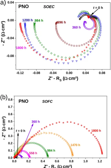
The results for PNO are reported in Fig. 4, the electrode operating either in SOEC or SOFC
conditions. In SOEC mode, inductive loops clearly appear; they are well-known measurement
artifacts when using three-electrode setup[42-44, 48, 49]. Such inductive loops can be accurately
fitted using a negative R//CPE.
-0.12 -0.08 -0.04 0.00 0.04 0.08 -0.08 -0.04 0.00 0.04 PNO SOEC t = 0 h 1200 h 1800 h 360 h 696 h 984 h - Z" ( W× cm² ) Z' - RS (W×cm²)
(a)
0.0 0.2 0.4 0.6 0.8 1.0 1.2 0.0 0.1 0.2 0.3 0.4 0.5 0.6 0.7 0.8 PNO SOFC t = 0 h 360 h 558 h 984 h 1470 h 1800 h - Z" ( W× cm² ) Z' - RS (W×cm²)(b)
Fig. 4. Nyquist plots of PNO aged under idc = 300 mA∙cm-2 at 700 °C up to 1800 h in (a)
SOEC mode and (b) SOFC mode.
An inductive loop on one side of the cell (here the SOEC side) has a corresponding positive R//CPE
12
response, virtually increasing the value of the polarization resistance. When measuring the whole
cell (SOEC + SOFC), this artifact does not appear because addition of the inductive loop and the
R//CPE cancel each other.
The way of fitting of the artifact is described in Fig. 5, from impedance data obtained with PNO
after 1200 h of ageing at 700 °C as an example. First, the artifact is fitted based on the inductive
tail, here on the SOEC impedance diagram, using a negative R//CPE (Fig. 5a). The fit is completed
using a series resistance, a R//CPE for the oxide oxidation reaction (OOR) at the SOEC electrode,
and a finite length Warburg for the gas diffusion [50].
1.45 1.50 1.55 1.60 -0.08 -0.06 -0.04 -0.02 0.00 0.02 RP 117 mW×cm 2 Fit
OORSOEC gaz diff.
Artifact PNO 700 °C SOEC -Z'' ( W× cm 2 ) Z' (W×cm2)
(a)
1.8 1.9 2.0 2.1 2.2 0.0 0.1 0.2 0.3 RP 117 mW×cm 2 - Z'' ( W × cm 2 ) Z' (W×cm2) PNO 700 °C SOFC ORRSOFC gaz diff. Artifact Fit(b)
13 3.4 3.5 3.6 3.7 0.0 0.1 0.2 ORRSOFC -Z'' ( W × cm 2 ) Z' (W×cm2) PNO 700 °C Whole cell OORSOEC gaz diff. Fit
(c)
Fig. 5. Impedance diagrams of PNO recorded after 1200 h of ageing at 700 °C as an example: (a) SOEC side; (b) SOFC side; (c) whole cell. The artifact is identified as an inductive loop at the SOEC side (a), together with the OORSOEC arc; (b) at the SOFC side, the ORRSOFC arc is calculated
taking into account this artifact. (c) Combination of the OORSOEC and ORRSOFC arcs results in the
whole cell impedance.
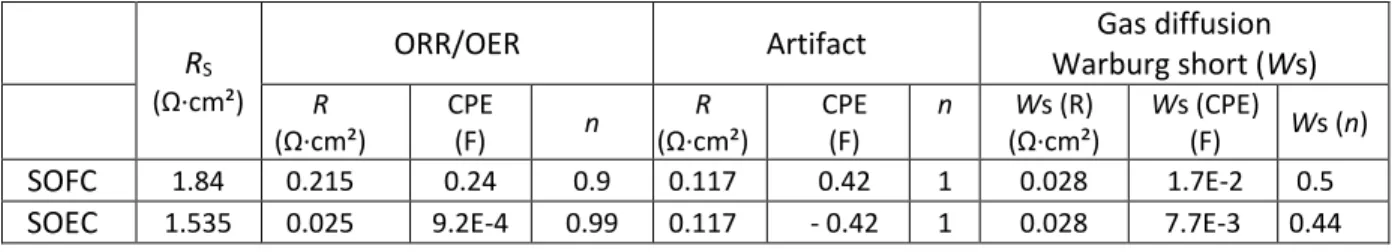
Table 1. Fitting results of impedance data analysis for PNO symmetrical half-cell.
RS
(Ω·cm²)
ORR/OER Artifact Gas diffusion
Warburg short (Ws) R (Ω·cm²) CPE (F) n R (Ω·cm²) CPE (F) n Ws (R) (Ω·cm²) Ws (CPE) (F) Ws (n) SOFC 1.84 0.215 0.24 0.9 0.117 0.42 1 0.028 1.7E-2 0.5
SOEC 1.535 0.025 9.2E-4 0.99 0.117 - 0.42 1 0.028 7.7E-3 0.44
The values obtained for the artifact and the gas diffusion are kept for fitting the SOFC impedance
diagram (Fig. 5b). An additional R//CPE arc is added to complete the fit, which represents the
oxygen reduction reaction (ORR) at the SOFC electrode. The results of the fitted impedance data
are summarized in Table 1.
The artifact does not appear on the total impedance diagram (Fig. 5c), which can be fitted using the
ORR from the SOFC side, the OOR from the SOEC side and the gas diffusion. Only the OOR and
14
Upon treatment of the artifact, the polarization resistance of PNO is found stable in SOEC mode
after 1800 h at 700 °C (close to 0% degradation, Fig. 4a). Only the inductive loop increases with
the ageing time. On the other hand, RP significantly increases in SOFC mode (+ 3350% after 1800 h,
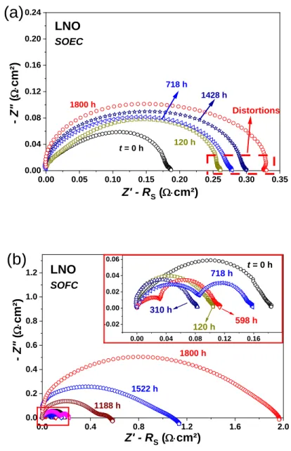
Fig. 4b). 0.00 0.05 0.10 0.15 0.20 0.25 0.30 0.35 0.00 0.04 0.08 0.12 0.16 0.20 0.24 Distortions LNO SOEC 718 h 1428 h 1800 h 120 h t = 0 h Z' - RS (W×cm²) - Z" ( W× cm² )
(a)
0.0 0.4 0.8 1.2 1.6 2.0 0.0 0.2 0.4 0.6 0.8 1.0 1.2 0.00 0.04 0.08 0.12 0.16 -0.02 0.00 0.02 0.04 0.06 LNO SOFC 1188 h 1522 h 1800 h - Z" ( W× cm² ) Z' - RS (W×cm²)(b)
718 h 598 h 310 h 120 h t = 0 hFig. 6. Nyquist plots of LNO aged at 700 °C, up to 1800 h under idc = 300 mA∙cm-2 in
(a) SOEC mode, and (b) SOFC mode.
The results for LNO are reported in Fig. 6. Distortions of the impedance diagrams appear after 700
15
mode, the electrochemical polarization resistance of LNO drastically increases from Rp = 0.18
Ω∙cm2 initially up to roughly 2 Ω∙cm2 after 1800 h (+1110 %). In SOEC mode, the increase is less
pronounced, Rp reaching 0.33 Ω∙cm2 after 1800 h (+180 %).
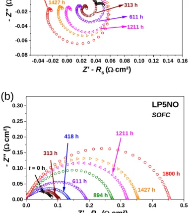
Finally, the results for LP5NO are given in Fig. 7. An inductive loop again appears in SOEC mode,
but to a lesser extent than for PNO. The oxygen electrode deteriorates more significantly in SOFC
mode (+350%) than in SOEC mode (close to 0%).
-0.04 -0.02 0.00 0.02 0.04 0.06 0.08 0.10 0.12 0.14 0.16 -0.08 -0.06 -0.04 -0.02 0.00 0.02 0.04 0.06 LP5NO SOEC 1211 h - Z" ( W× cm² ) t = 0 h 1427 h 611 h Z' - Rs (W×cm²) 1800 h 313 h
(a)
0.0 0.1 0.2 0.3 0.4 0.5 0.00 0.05 0.10 0.15 0.20 0.25 0.30 LP5NO SOFC 313 h t = 0 h 418 h 611 h 894 h 1211 h 1427 h 1800 h - Z" ( W× cm² ) Z' - RS (W×cm²)(b)
Fig. 7. Nyquist plots of LP5NO aged at 700 °C, up to 1800 h, under idc = 300 mA∙cm-2
in (a) SOEC mode and (b) SOFC mode.
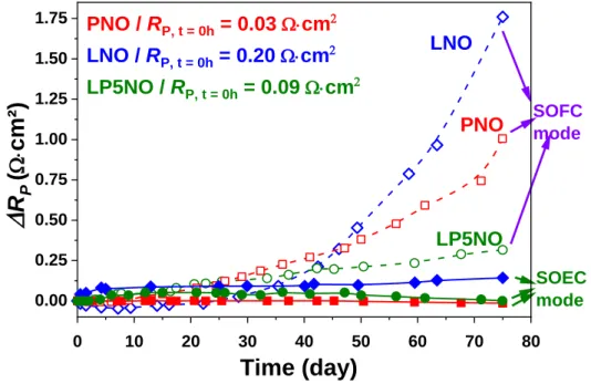
The time dependence of the additional polarization resistance RP = RPgt – RPini (RPini and RPgt being
16
electrodes in Fig. 8, in both SOEC and SOFC modes. In SOEC mode, the polarization resistances
of PNO and LP5NO are stable, while that of LNO slightly increases. In SOFC mode, the sample
suffering the highest degradation is LNO, then PNO and LP5NO. These degradations are far higher
than those observed in SOEC mode.
0 10 20 30 40 50 60 70 80 0.00 0.25 0.50 0.75 1.00 1.25 1.50 1.75 SOFC mode SOEC mode LP5NO PNO
R
P(
W×cm²
)
Time (day)
LNO PNO / RP, t = 0h = 0.03 W×cm2 LNO / RP, t = 0h = 0.20 W×cm2 LP5NO / RP, t = 0h = 0.09 W×cm2Fig. 8. Additional polarization resistance RP for PNO, LNO and LP5NO vs. time
during ageing at 700 °C, idc = 300 mA∙cm-2, in SOFC or SOEC mode.
In addition, the variation of series resistance (Rs) were also investigated for all three cells under
both SOFC and SOEC mode and depicted in supplementary information Fig. S1. Slight difference
in Rs for SOFC and SOEC mode may be due to some difference between the interfaces i.e.
electrode//GDCBL and GDCBL//YSZ on both sides of the half-cell (also might be due to the slight
differences in area of GDC or electrode, non-symmetrical electrode, or non-perfect polishing of the
surface for instance). A continuous increase in Rs is observed in SOFC mode but remarkably it is
17
different for all three cells. LNO cell shows the largest increase in Rs (0.4 Ω·cm2 after 1800 h) then
the PNO (0.17 Ω·cm2 after 1800 h) and LP5NO (0.06 Ω·cm2 after 1800 h).
In the last part, the origin of these degradations is discussed.
3.3.Origin of the degradations of LNO, PNO and LP5NO electrochemical performances during ageing under polarization
3.3.1. Post-mortem X-ray diffraction analyses
After the ageing experiments, the top surface of the electrodes was analyzed using X-ray diffraction.
PNO totally decomposes into Pr6O11, in addition with Pr4Ni3O10+δ and NiO on the SOFC side, or
PrNiO3-δ on the SOEC side. Slight decomposition of LNO and LPNO into Ln4Ni3O10δ and La2O3
occurs, but the extent of the decomposition is comparable in SOEC and SOFC modes and cannot
account for the differences in electrochemical performances. The lanthanide nickelate electrodes,
GDCBL and 8YSZ electrolytes are excellent SOFC/SOEC materials on their own; then, issues with
their electrochemical performances most probably come from reactivity at their interfaces when
stacked and exposed to high temperature [24, 47, 51].
3.3.2. Post-mortem FIB-SEM analysis
FIB-SEM micrographs of the three electrodes after the ageing experiments were performed on both
18
Fig. 9. FIB-SEM micrographs of LNO//GDCBL//8YSZ after 1800 h of ageing at 700 °C.
(a) SOEC side, (b) SOFC side.
Looking at the micrographs of the electrodes, the interfaces between LNO//GDCBL and
GDCBL//8YSZ seem rather good in SOEC mode (hence, no increase in Rs is observed under SOEC
mode), which may explain the good ageing results. Conversely, partial delamination between LNO
19
electrochemical performances. This partial delamination further explains the increase in Rs in SOFC
mode (supplementary information Fig S1c).
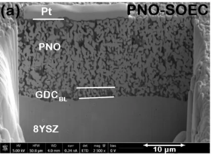
Fig. 10. FIB-SEM micrographs of PNO//GDCBL//8YSZ after 1800 h of ageing at 700
°C. (a) SOEC side, (b) SOFC side.
The PNO electrode (Fig. 10) delaminated on the SOFC side upon removal of the half-cell from the
20
in Rs was observed (supplementary information Fig S1a). In contrast, the morphology of the
half-cell on the SOEC side is quite good. These observations are very similar to those made for LNO
and lead to the same conclusion concerning the ageing behaviors.
Fig. 11. FIB-SEM micrographs of LP5NO//GDCBL//8YSZ after 1800 h of ageing at
21
Micrographs of LP5NO are shown in Fig. 11. Surprisingly, no delamination occurs on the SOFC
side, nor on the SOEC side.
The good performances obtained with LP5NO in SOFC mode, compared to LNO or PNO, may be
explained by this absence of delamination, as almost stable Rs value is observed (supplementary
information Fig S1b). But the differences in ageing of LP5NO either in SOFC or SOEC mode are
hardly explained by the micrographs. The authors are convinced that the reactivity at the
LPNO//GDCBL interfaces differs during the ageing, depending on how the electrode operates in
SOFC or SOEC mode.
To corroborate these results and assumption, EDX line-scan analyses of the electrodes have been
tentatively carried out from the electrode toward the electrolyte. Unfortunately, the results are
inconclusive, which likely means that the differences are subtle; more studies would be required to
be distinguished.
3.4. Comparison of the LPNO electrodes with classical perovskite materials
Many ageing studies about SOEC/SOFC complete cells containing perovskite electrodes as for
instance LSM [52-54] or LSCF [55] have been published. All of them conclude that the main
degradation occurs at the oxygen electrode concerned with the perovskite materials. In SOEC mode,
the degradations are related to an over-concentration of oxygen species at the oxygen
electrode//electrolyte interface, which progressively forms bubbles, ultimately leading to
delamination. The migration of cations from the oxygen electrode//electrolyte interface toward the
hydrogen electrode//electrolyte could also explain the delamination[56]. In SOFC mode, no clear
microstructural features explain the degradations, which are usually attributed to Sr enrichment at
22
It is noteworthy that we observed the opposite trend for the lanthanide nickelate, the oxygen
electrode working in SOEC being highly stable, while the SOFC one delaminates. The delamination
at the SOFC side may occur due to insufficient oxygen supply at the electrode //electrolyte interface:
indeed, the EIS setup does not allow forcing a gas flow inside the porosity of the electrode. Hence,
the degradation on the SOFC side could be lessened, or even removed using an optimized setup.
On the other hand, the higher stability of the lanthanide nickelates with respect to the perovskite
materials in SOEC is likely due to a significant difference in the ionic conductivity mechanism. For
the lanthanide nickelates, it results from their oxygen over-stoichiometry (i.e. additional oxide ions
in the network), while it arises from oxygen vacancies for the perovskites.
In the SOEC conditions, a large inflow of oxide ions takes place from the electrolyte toward the
electrode, which decreases the under-stoichiometry of the perovskite inducing a decrease of their
electrochemical performances. It is the contrary for the lanthanide nickelates that are able to insert
additional oxide ions. This might explain the over-concentration of oxygen species occurring at the
perovskite electrode//electrolyte interface working in SOEC, leading to delamination, while no such
issues are observed in the current study for the lanthanide nickelates.
The next step will be to confirm the performances and ageing capability of the lanthanide nickelate
in a real SOEC setup.
4. Conclusions
This study reported the ageing behaviour of electrodes of La2NiO4+δ, Pr2NiO4+δ, and their mixed
products La2-xPrxNiO4+δ, with x = 0.5, 1 and 1.5, with or without polarization, at 700 °C. These
23
First, the chemical stability of the raw powders was studied at 600 °C, 700 °C, and 800 °C. LNO
was quite stable whatever the temperature, while PNO decomposed into a mixture of Pr6O11,
PrNiO3-δ, Pr4Ni3O10+δ and NiO as previously reported. Among the LPNO materials, the x = 0.5
composition (LP5NO) was chemically as stable as LNO, the ones with x = 1 or 1.5 (LP10NO or
LP15NO) decomposing as their parent phase PNO.
The electrochemical stability of all these materials as oxygen electrode was rather good without
polarization over one month. A comparatively large increase in the polarization resistance of LNO
and PNO occurred, while all the LPNO compounds were stable.
However, under polarization (idc = 300 mA∙cm-2), PNO, LNO and LP5NO significantly damaged
when working in SOFC conditions, i.e. in oxygen reduction reaction, in the RP order LNO > PNO
> LP5NO. Delamination occurred at the interface between LNO or PNO and GDCBL, which was
believed to come from a poor supply of oxygen inside the porosity of the electrode, toward the
active sites for the oxygen reduction reaction. This delamination accounted for the increase of the
polarization resistance of both electrodes. No delamination was observed for LP5NO, which may
explain its better final performances than LNO or PNO. In that case, the degradations may come
from a progressive reactivity at the interfaces between LP5NO and GDC, but no proof could be
provided by XRD or FIB-SEM analyses.
The behaviour of these electrodes in SOEC conditions, i.e. for the oxide ion oxidation reaction, was
remarkable. If a slight increase of the polarization resistance was measured for LNO (+ 0.14 Ω∙cm2
after 1800 h), the polarization resistances of PNO and LP5NO were stable at respectively 0.03
Ω∙cm2 and 0.09 Ω∙cm2 at 700 °C for 1800 h. In addition, no delamination was observed in contrast
with previous reports on LSC or LSCF. These results are very promising for the development of an
24
Acknowledgments
This work was performed under PEREN project (reference: ANR-2011-PREG-016-05). The
authors wish to gratefully acknowledge the Agence Nationale de la Recherche (A.N.R., France) for
supporting these scientific works and for the financial support.
References
[1] R. Knibbe, A. Hauch, J. Hjelm, D. Ebbesen Sune, M. Mogensen, Durability of Solid Oxide Cells, in: Green, 2011, pp. 141.
[2] H. Yokokawa, H. Tu, B. Iwanschitz, A. Mai, Journal of Power Sources, 182 (2008) 400-412. [3] R.E. van Doorn, I.C. Fullarton, R.A. de Souza, J.A. Kilner, H.J.M. Bouwmeester, A.J. Burggraaf, Solid State Ionics, 96 (1997) 1-7.
[4] G.C. Kostogloudis, C. Ftikos, Solid State Ionics, 126 (1999) 143-151.
[5] V.V. Kharton, A.P. Viskup, D.M. Bochkov, E.N. Naumovich, O.P. Reut, Solid State Ionics, 110 (1998) 61-68.
[6] A.J. Jacobson, Chemistry of Materials, 22 (2010) 660-674.
[7] A. Petric, P. Huang, F. Tietz, Solid State Ionics, 135 (2000) 719-725.
[8] M.Y. Lu, J.G. Railsback, H. Wang, Q. Liu, Y.A. Chart, S.-L. Zhang, S.A. Barnett, Journal of Materials Chemistry A, 7 (2019) 13531-13539.
[9] M.-B. Choi, B. Singh, E.D. Wachsman, S.-J. Song, Journal of Power Sources, 239 (2013) 361-373.
[10] V.C. Kournoutis, F. Tietz, S. Bebelis, Fuel Cells, 9 (2009) 852-860.
[11] M. Søgaard, P.V. Hendriksen, M. Mogensen, F.W. Poulsen, E. Skou, Solid State Ionics, 177 (2006) 3285-3296.
[12] J. Januschewsky, M. Ahrens, A. Opitz, F. Kubel, J. Fleig, Advanced Functional Materials, 19 (2009) 3151-3156.
[13] K. Kurata, Y. Toyota, T. Sato, E. Niwa, K. Shozugawa, M. Matsuo, T. Hashimoto, Journal of the Ceramic Society of Japan, 125 (2017) 227-235.
[14] Y. Bo, Z. Wenqiang, X. Jingming, C. Jing, International Journal of Hydrogen Energy, 33 (2008) 6873-6877.
[15] S. Sun, Z. Cheng, Journal of The Electrochemical Society, 164 (2017) F3104-F3113. [16] G.C. Kostogloudis, G. Tsiniarakis, C. Ftikos, Solid State Ionics, 135 (2000) 529-535. [17] D. Oh, D. Gostovic, E.D. Wachsman, Journal of Materials Research, 27 (2012) 1992-1999. [18] F. Wang, K. Yamaji, D.-H. Cho, T. Shimonosono, H. Kishimoto, M.E. Brito, T. Horita, H. Yokokawa, Solid State Ionics, 225 (2012) 157-160.
[19] V. Vibhu, S. Yildiz, I.C. Vinke, R.-A. Eichel, J.-M. Bassat, L.G.J. de Haart, Journal of The Electrochemical Society, 166 (2019) F102-F108.
[20] S.J. Kim, G.M. Choi, Solid State Ionics, 262 (2014) 303-306.
[21] F. Wang, T. Nakamura, K. Yashiro, J. Mizusaki, K. Amezawa, Physical Chemistry Chemical Physics, 16 (2014) 7307-7314.
25
[23] S. Takahashi, S. Nishimoto, M. Matsuda, M. Miyake, Journal of the American Ceramic Society, 93 (2010) 2329-2333.
[24] R. Sayers, J. Liu, B. Rustumji, S.J. Skinner, Fuel Cells, 8 (2008) 338-343.
[25] Y. Nigara, P. Odier, A.M. Anthony, Science of Ceramics 11, The Swedish Sot. Ceramics,, 11 (1981) 551-557.
[26] J.M. Bassat, P. Odier, J.P. Loup, Journal of Solid State Chemistry, 110 (1994) 124-135. [27] V. V. Kharton, A. P. Viskup, E. N. Naumovich, F. M. B. Marques, Journal of Materials Chemistry, 9 (1999) 2623-2629.
[28] S.J. Skinner, J.A. Kilner, Solid State Ionics, 135 (2000) 709-712.
[29] E. Boehm, J.M. Bassat, P. Dordor, F. Mauvy, J.C. Grenier, P. Stevens, Solid State Ionics, 176 (2005) 2717-2725.
[30] J.-M. Bassat, V. Vibhu, C. Nicollet, A. Flura, S. Fourcade, J.-C. Grenier, A. Rougier, ECS Transactions, 78 (2017) 655-665.
[31] V. Vibhu, A. Rougier, C. Nicollet, A. Flura, S. Fourcade, N. Penin, J.-C. Grenier, J.-M. Bassat, Journal of Power Sources, 317 (2016) 184-193.
[32] C. Ferchaud, J.-C. Grenier, Y. Zhang-Steenwinkel, M.M.A. van Tuel, F.P.F. van Berkel, J.-M. Bassat, Journal of Power Sources, 196 (2011) 1872-1879.
[33] M.A. Laguna-Bercero, H. Monzón, A. Larrea, V.M. Orera, Journal of Materials Chemistry A, 4 (2016) 1446-1453.
[34] X. Tong, F. Zhou, S. Yang, S. Zhong, M. Wei, Y. Liu, Ceramics International, (2017).
[35] C. Zhao, Q. Zhou, T. Zhang, L. Qu, X. Yang, T. Wei, Materials Research Bulletin, 113 (2019) 25-30.
[36] A. Flura, S. Dru, C. Nicollet, S. Fourcade, A. Rougier, J.M. Bassat, J.C. Grenier, 5th International Conference on Fundamentals and Development of Fuel Cells “FDFC 2013”, (2013). [37] V. Vibhu, A. Rougier, C. Nicollet, A. Flura, J.-C. Grenier, J.-M. Bassat, Solid State Ionics, 278 (2015) 32-37.
[38] V. Vibhu, I.C. Vinke, R.-A. Eichel, J.-M. Bassat, L.G.J. de Haart, ECS Transactions, 91 (2019) 1327-1339.
[39] S.J. Kim, K.J. Kim, A.M. Dayaghi, G.M. Choi, International Journal of Hydrogen Energy, 41 (2016) 14498-14506.
[40] P. Courty, H. Ajot, C. Marcilly, B. Delmon, Powder Technology, 7 (1973) 21-38.
[41] A.D. Rougier, A. Flura, C. Nicollet, V. Vibhu, S. Fourcade, E. Lebraud, J.-M. Bassat, J.-C. Grenier, ECS Transactions, 68 (2015) 817-823.
[42] S.B. Adler, Journal of The Electrochemical Society, 149 (2002) E166-E172.
[43] S.B. Adler, B.T. Henderson, M.A. Wilson, D.M. Taylor, R.E. Richards, Solid State Ionics, 134 (2000) 35-42.
[44] J. Winkler, P.V. Hendriksen, N. Bonanos, M. Mogensen, Journal of The Electrochemical Society, 145 (1998) 1184-1192.
[45] A. Flura, S. Dru, C. Nicollet, V. Vibhu, S. Fourcade, E. Lebraud, A. Rougier, M. Bassat, J.-C. Grenier, Journal of Solid State Chemistry, 228 (2015) 189-198.
[46] V. Vibhu, A. Flura, C. Nicollet, S. Fourcade, N. Penin, J.-M. Bassat, J.-C. Grenier, A. Rougier, M. Pouchard, Solid State Sciences, 81 (2018) 26-31.
[47] A. Flura, C. Nicollet, V. Vibhu, B. Zeimetz, A. Rougier, J.-M. Bassat, J.-C. Grenier, Journal of The Electrochemical Society, 163 (2016) F523-F532.
[48] M. Cimenti, A.C. Co, V.I. Birss, J.M. Hill, Fuel Cells, 7 (2007) 364-376. [49] M. Cimenti, V.I. Birss, J.M. Hill, Fuel Cells, 7 (2007) 377-391.
[50] A. Flura, C. Nicollet, S. Fourcade, V. Vibhu, A. Rougier, J.M. Bassat, J.C. Grenier, Electrochimica Acta, 174 (2015) 1030-1040.
26
[51] A. Montenegro-Hernández, A. Soldati, L. Mogni, H. Troiani, A. Schreiber, F. Soldera, A. Caneiro, Journal of Power Sources, 265 (2014) 6-13.
[52] C. Graves, S.D. Ebbesen, S.H. Jensen, S.B. Simonsen, M.B. Mogensen, Nat Mater, 14 (2015) 239-244.
[53] M.J. Heneka, E. Ivers-Tiffée, ECS Proceedings Volumes, 2005-07 (2005) 534-543.
[54] A.V. Virkar, J. Nachlas, A.V. Joshi, J. Diamond, Journal of the American Ceramic Society, 73 (1990) 3382-3390.
[55] S.P. Simner, M.D. Anderson, M.H. Engelhard, J.W. Stevenson, Electrochemical and Solid-State Letters, 9 (2006) A478-A481.
[56] G. Petot-Ervas, C. Petot, J.M. Raulot, J. Kusinski, Defect and Diffusion Forum, 237-240 (2005) 843-848.
Graphical Abstract
Description (20-35 words): The investigations of Lanthanide nickelates as oxygen electrodes for solid oxide cells show a large degradation in SOFC mode while a very stable behaviour in SOFC mode.