HAL Id: hal-00425158
https://hal.archives-ouvertes.fr/hal-00425158
Submitted on 5 Feb 2013HAL is a multi-disciplinary open access archive for the deposit and dissemination of sci-entific research documents, whether they are pub-lished or not. The documents may come from teaching and research institutions in France or abroad, or from public or private research centers.
L’archive ouverte pluridisciplinaire HAL, est destinée au dépôt et à la diffusion de documents scientifiques de niveau recherche, publiés ou non, émanant des établissements d’enseignement et de recherche français ou étrangers, des laboratoires publics ou privés.
Analysis of the response of a rotor system containing a
breathing crack
Jean-Jacques Sinou
To cite this version:
Jean-Jacques Sinou. Analysis of the response of a rotor system containing a breath-ing crack. Key Engineering Materials, Trans Tech Publications, 2009, 413-414, pp.479-486. �10.4028/www.scientific.net/KEM.413-414.479�. �hal-00425158�
Analysis of the response of a rotor system containing a breathing crack
Jean-Jacques Sinou
1,a1Laboratoire de Tribologie et Dynamique des Systèmes UMR CNRS 5513 Ecole Centrale de Lyon, 36 avenue Guy de Collongues 69134 Ecully cedex France
a jean-jacques.sinou@ec-lyon.fr
Keywords: dynamic analysis, rotor, crack, breathing mechanism, non-linear analysis
Abstract. The purpose of this paper is to investigate the influence of the presence of transverse
cracks in rotors. The dynamic response of the cracked rotor is evaluated by expanding the changing stiffness of the crack (i.e. the breathing mechanism) as a truncated Fourier series and then using the Harmonic Balance Method. The crack detection is based on the use of the 2X and 3X super-harmonic frequency components of the non-linear dynamical behaviour at the associated sub-critical resonant peaks. Various parametric studies including the effects of the crack depth and location, and the crack–unbalance interaction on the dynamic of a crack rotor are undertaken. It will be illustrated that the emerging of super-harmonic frequency components and/or antiresonances can provide useful information on the presence of cracks and may be used on an on-line crack monitoring rotor system for small levels of damage.
Introduction
The effect of crack in rotors through non-destructive testing is important to ensure the integrity of structural components for a wide range of engineering applications. In recent years a lot of effort has been devoted to the detection of transverse cracks in shafts [1-11]. In most of the studies for crack detection in rotor systems, researchers used changes in natural frequencies and evolution of the non-linear behaviour of the system at the super-harmonics components as the diagnostic tools. In this paper it will be shown that not only an appropriate use of the 2X and 3X uper-harmonic frequency components of the non-linear dynamical behaviour but also the antiresonances of the super-harmonics components may be useful for crack identification in rotor systems.
First of all, a brief introduction of the rotor system and the definition of damage based on the notion of stiffness reduction is described. Then, the paper begins by considering classical detection techniques for non-linear mechanical systems based on changes in the natural frequencies, evolution of the Frequency Response Function, and appearance of sub-harmonic resonances and the nX harmonic components. Secondly, the effects of crack size and location and the crack-unbalance interactions are presented. Finally, the emergence of antiresonances for the super-harmonics components of the non-linear response of the cracked rotor are used for the detection of the crack location.
Model of the cracked rotor
The layout of the cracked rotor system under consideration is shown in Fig. 1. The rotor is composed of a shaft of length 0.5m with one disc at the mid-span. The material properties and dimensions of the rotor are given in Table 1. It is discretized into Timoshenko beam finite elements, with four degrees of freedoms at each node, the axial and torsional degrees of freedom being not considered. After assembling the various shaft elements and the rigid disc, the equations of the uncracked rotor can be written as
(
)
+ + Ω + = +
Mx$$ C G x Kx$ Q W (1)
where x$$ , x$ , and x are the acceleration, velocity and displacement of the degree-of freedom of the cracked rotor system. M , C, G and K define the mass, damping, gyroscopic and stiffness matrices, respectively. Q and W are the vector of gravity force and imbalance force, respectively. Then, the crack section is defined by the reduction of the second moment of area ∆ of the element I
at the location of the crack (see the paper of Mayes and Davies [3-4] for more details). By using Rayleigh's method, they obtained that the change in ∆ satisfied I
(
) (
)
(
)
( )
( )
2( )
0 1 0 . 1
I I I I R l F
∆ − ∆ = −
ν
µ
(2)where I , 0 R , l, ν, µ, and F
( )
µ are the second moment of area, the shaft radius, the length of the section, the Poisson's ratio, the non-dimensional crack depth, and the compliance functions varied with the non-dimensional crack depth µ =h R where h defines the crack depth of the shaft, respectively. Finally, the complete rotor model with a breathing crack is given by(
) (
f ( t ) crack)
+ + Ω + − = +
Mx$$ C G x$ K K x Q W (3)
where Kcrack is the stiffness matrix due to the transversal crack that can be obtained by using standard finite elements. f
( )
t the function representing the breathing effect. One of the usual models of a crack is that of Mayes and Davies [3] where the opening and closing of the crack was described by a cosine function by assuming that the gravity force is much greater that the imbalance force, the function describing the breathing crack may given by f t( )= −(
1 cos( )
Ωt)
2 where Ω is the rotational speed of the rotor. For f(t)=0, the crack is totally closed and the cracked rotor stiffness is similar to the uncracked rotor stiffness. For f(t)=1, the crack is full open.Fig.1: picture of the cracked rotor system
Parameters Physical dimension
Young's modulus of elasticity E Poisson ratio ν Density ρ Shaft length 2.1×10¹¹ N.m-2 0.3 7800 kg.m-3 0.5m Table 1: Detail of the rotor model
Non-linear analysis
The non-linear dynamic response of the rotor can be approximated by a finite Fourier series with a fundamental frequency
( )
( )
(
)
1 cos t sin t m n n n = = 0+∑
n ω + n ω X A A B (4)where m represents the number of harmonics considered in the solution. A , 0 A and n B (for n
n=1,...,m) define the unknown coefficients of the finite Fourier series. Assuming that the crack breathing behavior can be approximated by finite Fourier series of order m
(
)
(
( )
( )
)
1 , , ( ) cos t sin t m crack n t f t n n = = = 0+∑
n + n f xω
K C Cω
Sω
(5)The harmonic frequency components A and n B (for n=1,...m) can be determined by resolving the n
following equations 2 2 2 2 and 2 2 n n n n ⎡ ⎤ ⎡ ⎤ ⎡− + ⎤⎡ ⎤ ⎡− + ⎤⎡ ⎤ = ⎢ ⎥ ⎢ ⎥ ⎢ − − + ⎥⎢ ⎥⎣ ⎦ ⎢ − − + ⎥⎢ ⎥⎣ ⎦ ⎣ ⎦ ⎣ ⎦ ⎣ ⎦ ⎣ ⎦ W 1 1 1 n n W 1 1 1 n n A S + S A S M K D M K D = B C + C B C D M K D M K ω ω ω ω ω ω ω ω (6) for n>1. W 1
S and C are the Fourier components of the global unbalance force (i.e. 1W
(
, ,t)
= Wcos( )
t + Wsin( )
t1 1
W x
ω
Cω
Sω
).As previously explained in the paper [11], the harmonic components An and Bn of the response can be partitioned and condensed on the cracked element cn = ⎣⎡ cn cn⎤T
⎦ U A B by the following relation c T n c c u u T n n u n n n n n n ⎡ ⎤ ⎡ ⎤ ⎡ ⎤ ⎢ ⎥ ⎢ ⎥ = =⎣ ⎦ = ⎢ ⎥ ⎢ ⎥ ⎣ ⎦ ⎣ ⎦ U A U A B A B U B (7)
where the subscript ‘n’ represents ‘‘nth harmonic components’’, the superscript ‘u’ represents ‘‘uncracked’’, and the superscript ‘c’ represents ‘‘cracked’’. The Fourier components A and cn B cn
are associated with the degrees of freedom at the crack location, and the Fourier components A un
and B are associated with the others degrees of freedom. Considering Eq. (7), the equations of un
motion (6) can be rewritten in the following form
cc cu c c W f n n n n T n 1 1 n uc uu u u W f n n n n 1 1 n 1 1 n = = = ⎡ ⎤ ⎡ ⎤ ⎡ ⎤ ⎡δ + ⎤ ⎢ ⎥ ⎢ ⎥ ⎢= ⎥= ⎢ ⎥ ⎢ ⎥ ⎢ ⎥ ⎢δ ⎥ ⎢δ + ⎥ ⎣ ⎦ ⎣ ⎦ ⎣ ⎦ ⎣ ⎦ U F S S U F C C (8) with
cc cu 2 2 n n uc uu 2 2 n n
n
n
n
n
⎡
⎤
=
⎡
−
+
⎤
⎢
⎥
⎢
−
−
+
⎥
⎣
⎦
⎣
⎦
TM K
D
D
M K
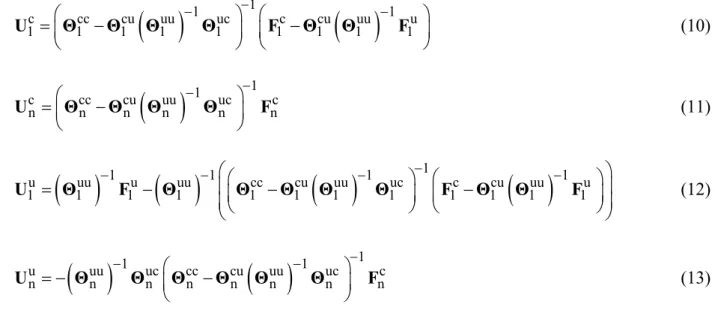
(9)After calculation, the first and nth harmonic components of cracked and uncracked elements (i.e. c
1
U , U , cn U and 1u U can be given on the crack element by cn
( )
1 1( )
1 c cc cu uu uc c cu uu u 1 1 1 1 1 1 1 1 1 − − − ⎛ ⎞ ⎛ ⎞ =⎜ − ⎟ ⎜ − ⎟ ⎝ ⎠ ⎝ ⎠ U F F (10)( )
1 1 c cc cu uu uc c n n n n n n − − ⎛ ⎞ =⎜ − ⎟ ⎝ ⎠ U F (11)( )
1( )
1( )
1 1( )
1 u uu u uu cc cu uu uc c cu uu u 1 1 1 1 1 1 1 1 1 1 1 1 − − − ⎛⎛ − ⎞ ⎛ − ⎞⎞ ⎜ ⎟ = − ⎜⎜ − ⎟ ⎜ − ⎟⎟ ⎝ ⎠ ⎝ ⎠ ⎝ ⎠ U F F F (12)( )
1( )
1 1 u uu uc cc cu uu uc c n n n n n n n n − − ⎛ − ⎞ = − ⎜ − ⎟ ⎝ ⎠ U F (13)Response of the cracked rotor and evolution of the 2X and 3X harmonic components
Figure 2 shows the steady state response for both the healthy rotor and the rotor with a breathing crack. It is observed that the 2X resonances are predicted when the running speed is approximately one-half of the first and second resonance frequencies (see the marks 2 and 8 for one-half of the first resonance frequency , and the marks 4 and 10 for one-half of the second resonance frequency). The 3X harmonic component of the system response can be identified at one-third of the first resonance frequency, as indicated by the mark 1 (in the vertical direction).
Figures 3 illustrate the effects of the crack size and location on the 2X super-harmonic frequency components and the 3X super-harmonic frequency components. Due to the presence of the crack, the second harmonic components increase when the rotational speed reaches 1 2 and 1 of the critical speeds. The third harmonic components increase near the rotational speeds at 1 3 , 1 2 and 1 of the critical speeds. Moreover, a small decrease in the critical speeds of the rotor system is also observed, due to the reduction in system stiffness resulting from the presence of the crack. Finally, it clearly appears the location of antiresonances for both the 2X super-harmonic frequency components and the 3X super-harmonic frequency components and the shift in these antiresonances depend on the crack location, but are not affected by the crack size.
Fig.2: Vertical and horizontal steady-state responses of the healthy and cracked rotors at 0.15m of
the left end with the imbalance situated at 0.1m from the left end ( healthy rotor, cracked rotor, position of the crack at 0.175m and µ=1 )
(a) (b)
(c) (d)
Fig.3: Evolution of the 2X and 3X harmonic components for various crack depth and location (a-c) order 2 (b-d) order 3 (a-b) µ=1, µ=0.75, µ=0.5, µ=0.25 with Lcrack=0.175m
(c-d) Lcrack=0.075m, Lcrack=0.125m, Lcrack=0.175m, Lcrack=0.225m with µ=1
Figures 4 illustrate the effects of the crack–unbalance interaction on the 2X harmonic components at the 1 2 first sub-critical resonance. It clearly appears that the relative orientation angle between the unbalance of the cracked rotor and the crack, and the unbalance intensity drastically affect the evolutions of the second super-harmonic frequency components. Moreover, it may be observed that the phenomenon of the “double loops” at 1 2 of the critical speed (i.e a loop with an internal loop) that is classically used for the detection of cracks in rotor may disappear due the crack –unbalance interaction. However, in all cases, the appearance of the 2X and 3X harmonic components are clearly identified (see Figure 5).
(a) (b)
(c) (d)
Fig.4: Crack–unbalance interaction on the 2X harmonic components and orbits at the 1 2 first sub-critical resonance (with Lcrack=0.225m and µ=1) (a-b) mede=10-5kgm (c-d) mede=10-7kgm
(a) (b)
Fig.5: Evolution of the 2X and 3X harmonic components for various unbalance (with Lcrack=0.225m and µ=1) (a) mede=10-5kgm (b) mede=10-7kgm
Detection of the crack location based on the antiresonances
As previously explained in the first part of the paper, the crack position affect the 2X and3X harmonic components with the appearances of new antiresonances. This fact may clearly explained by considering Eq. (8). It appears that the presence of the breathing crack only adds an excitation
c n
F on the crack element for the nX harmonic components (for n>1). So, the position of the crack
can be identified by considering the evolution of antiresonances of the 2X and 3X harmonic components. Figs. 6 illustrate the evolution of the second and third orders of the non-linear
responses of the cracked rotor for various crack depths and locations. The emerging and location of new antiresonance and the shift in the antiresonance depend on the crack location. For example, it can be observed that the minimum of antiresonances (in frequency) for the second and third order harmonic components of the cracked rotor system appears at the presence of the crack (see marks A and/or B in Figs. 6). Moreover, it is observed that the detection of the crack location can be performed even if the crack is small ( see Fig. 6(a) and (b) for example).
Conclusion
This paper highlights the possibility of crack detection through the observation of the non-linear dynamic behaviour of rotor systems. The emerging of both the 2X super-harmonic frequency components and the 3X super-harmonic frequency components may provide useful information on the presence of a crack and may be used on an on-line crack monitoring rotor system.
Then, it is illustrated that the emerging and location of new antiresonances for the super-harmonics components of the non-linear cracked rotor depend on the crack location and can provide useful information on the presence of crack
Acknowledge
The author gratefully acknowledges the financial support of the french National Research Agency through the program Young researcher ANR-07-JCJC-0059-01-CSD 2.
References
[1] J. Wauer Dynamics of Cracked Rotors: Literature Survey, Applied Mechanics Review, 43
(1990), 13-17.
[2] A.D. Dimarogonas A.D. Vibration of Cracked Structures: A State of the Art Review, Engineering Fracture Mechanics, 55 (1996) 831-857.
[3 ] I.W. Mayes and W.G.R. Davies. Analysis of the Response of a Multi-Rotor-Bearing System Containing a Transverse Crack in a Rotor Transactions of the ASME Journal of Vibration, Acoustics, Stress, and Reliability in Design, 106(1984), 139-145.
[4] W. G. R. Davies and I. W. Mayes. The Vibrational Behaviour of a Multi-Shaft, Multi-Bearing System in the Presence of a Propagating Transverse Crack. Transactions of the ASME Journal of Vibration, Acoustics, Stress, and Reliability in Design., 106(1984), 146-153.
[5] R. Gasch. Dynamic Behaviour of a simple rotor with a cross-sectional Crack. IMechE Conference on Vibrations in Rotating Machinery, (1976), 123-128
[6] R. Gasch. A Survey of the Dynamic Behaviour of a Simple Rotating Shaft with a Transverse Crack. Journal of Sound and Vibration, 160(1993), 313-332.
[7] N. Pugno, C. Surace, and R. Ruotolo Evaluation of the Non-linear Dynamic Response to Harmonic Excitation of a Beam with Several Breathing Cracks. Journal of Sound and Vibration,. 235(2000), 749-762.
[8] M.I. Friswell , and J.E.T.P. Penny 2002 International Journal of Structural Health Monitoring,. Crack Modelling for Structural Health Monitoring. 1(2002), 139-148.
[9] T.A. Henry, and B.E. Okah-Avae. Vibrations in Cracked Shafts, IMechE Conference on Vibrations in Rotating Machinery, (1976), 15-19.
[10] J.-J. Sinou, A.W. Lees. A non-linear study of a cracked rotor. European Journal of Mechanics A/Solids, 26 (2007) 152–170.
[11]J-J. Sinou. Detection of cracks in rotor based on the 2X and 3X super-harmonic frequency components and the crack–unbalance interactions Communications in Nonlinear Science and Numerical Simulation 13 (2008) 2024–2040.
(a) (b)
(c) (d)
(e) (f)
Fig.6: Detection of the crack location based on the antiresonances of the second and third orders (a,c,e) order 2 (b,d,f) order 3 (a,b)Lcrack=0.125m and µ=0.25 (c,d)Lcrack=0.225m and µ=1