HAL Id: hal-01511825
https://hal.archives-ouvertes.fr/hal-01511825
Submitted on 21 Apr 2017
HAL is a multi-disciplinary open access
archive for the deposit and dissemination of
sci-entific research documents, whether they are
pub-lished or not. The documents may come from
teaching and research institutions in France or
abroad, or from public or private research centers.
L’archive ouverte pluridisciplinaire HAL, est
destinée au dépôt et à la diffusion de documents
scientifiques de niveau recherche, publiés ou non,
émanant des établissements d’enseignement et de
recherche français ou étrangers, des laboratoires
publics ou privés.
Fault Diagnosis and Fault-Tolerant Control of an
Octorotor UAV using motors speeds measurements
Majd Saied, Benjamin Lussier, Isabelle Fantoni, Hassan Shraim, Clovis Francis
To cite this version:
Majd Saied, Benjamin Lussier, Isabelle Fantoni, Hassan Shraim, Clovis Francis. Fault Diagnosis
and Fault-Tolerant Control of an Octorotor UAV using motors speeds measurements. 20th
Interna-tional Federation of Automatic Control World Congress (IFAC WC 2017), Jul 2017, Toulouse, France.
pp.5263-5268. �hal-01511825�
Fault Diagnosis and Fault-Tolerant Control
of an Octorotor UAV using motors speeds
measurements
Majd Saied∗,∗∗ Benjamin Lussier∗ Isabelle Fantoni∗ Hassan Shraim∗∗ Clovis Francis∗∗
∗Sorbonne Universit´es, Universit´e de Technologie de Compi`egne,
CNRS, UMR 7253 Heudiasyc, 60200 Compi`egne, France (e-mail: { majd.saied, benjamin.lussier, isabelle.fantoni } @hds.utc.fr).
∗∗Universit´e Libanaise, Facult´e de G´enie, Centre de Recherche
Scientifique en Ing´enierie (CRSI), Liban (e-mail: { cfrancis, hassan.shraim } @ul.edu.lb)
Abstract: This paper presents an active fault-tolerant control strategy (AFTCS) for an octorotor unmanned aerial vehicle (UAV) regarding several motors failures or rotors damages. A complete AFTC architecture including error detection, fault isolation and system recovery is presented. The diagnosis system is based on the motors speeds and currents measurements. Once the motor failure or the rotor loss is diagnosed, a recovery algorithm is applied. It uses the pseudo-inverse control allocation approach to redistribute the control efforts among the healthy actuators. This architecture is validated in real flights.
Keywords: Fault-Tolerant Control, Fault Diagnosis, Unmanned Aerial Vehicles; 1. INTRODUCTION
The last decade has witnessed many developments in the area of rotary-wing unmanned aerial vehicles. This is due to the large number of UAVs civil applications such as surveillance, search and rescue missions, equip-ment monitoring and security applications. However their use is limited by different operational and technical con-straints. UAVs must imperatively meet flight conditions and comply with air traffic rules like manned aircrafts. This enforces them to guarantee a certain level of technical reliability to prevent crashes in order to ensure security on the ground, and a satisfactory reliability from a behavioral standpoint to ensure the safety of other aircrafts in flight. Thus new generations of UAVs should be equipped with fault-tolerant control algorithms capable of monitoring the vehicle health and taking action when needed.
For rotary-wing UAVs, quadrotors lack available redun-dancy, which is critical for fault tolerance. A complete loss of a rotor for a quadrotor results in a vehicle that is not fully controllable (Lanzon et al. (2012), Lippiello et al. (2014)). An obvious alternative is to consider multirotors with redundant actuators, where a full controllability of the UAV is maintained even after actuators failures. This fault tolerance justifies the additional costs and complexity
? This work was carried out and funded in the framework of the Labex MS2T (Reference ANR-11-IDEX-0004-02), the ROBOTEX Equipment of Excellence (Reference ANR-10-EQPX-44) and the FUI AIRMES. The Labex MS2T and ROBOTEX were supported by the French Government, through the program Investments for the future managed by the National Agency for Research.
This work has been partially funded with support from the National Council for Scientfic Research in Lebanon.
in designing systems with hardware redundancy.
Only few theoretical works have recently studied the fault-tolerant control problem of hexarotors vehicles under ac-tuators failures (Schneider et al. (2012), Du et al. (2015)). The control allocation is the fault-tolerant control tech-nique that was the most used for octorotors. In (Marks et al. (2012)), the authors proposed the use of a redis-tributed pseudo-inverse method of control reallocation for the fault-tolerant control of a star-shaped octorotor UAV. This method allocates the controller commands to the actuators while avoiding actuator saturation. A dynamic control allocation method is developed in (Merheb et al. (2014)), for an octorotor, combined with a sliding mode observer for fault diagnosis purpose. Whenever a fault or a total failure of a rotor is detected, the gain vector of the dynamic control allocator is updated resulting in the redistribution of the control effort. The works in (Alwi and Edwards (2013), Alwi and Edwards (2015)) present fault-tolerant control schemes based on linear parameter varying system representation and utilize a combination of sliding-mode ideas and control allocation in order to take full advantage of the available redundant rotors in the octorotor configuration.
Only few papers about fault-tolerant control of overac-tuated multirotors consider the fault diagnosis in their studies (Saied et al. (2015b), Saied et al. (2015a)), as others usually assume that the faults are perfectly iden-tified. However, this is not a realistic hypothesis since fault diagnosis is a very challenging topic, especially for systems with redundant actuators. In this paper, a com-plete error detection, fault diagnosis and system recovery architecture for a coaxial octorotor is presented as our main contribution. A pseudo-inverse control allocation
ap-proach is applied for system recovery when one or multiple simultaneous or successive motors failures or propellers losses occur. An error detection and fault diagnosis module is proposed to reconfigure the control allocation matrix and distinguish between a motor failure and a propeller loss. This module uses the speeds and electric currents of the brushless motors measured by their electronic speed controllers.
This paper is organized as follows: Section II presents the dynamic model of the coaxial octorotor. Section III is dedicated to the detection and recovery algorithms. The results are validated with real experiments in section IV, and the paper concludes with perspectives in section V.
2. OCTOROTOR DYNAMICS AND CONTROL STRATEGY
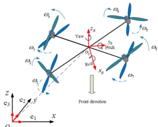
The coaxial octorotor configuration presented in Fig. 1 is used as a test platform for the proposed fault-tolerant control architecture. Its dynamic equations are given by:
˙ X(t) = f (X(t)) + g(X(t))τ (t) (1) where f (X(t)) = ˙ x 0 ˙ y 0 ˙ z −g aφ c1qr − c2qΩr aθ c4pr + c5pΩr aψ c7pq , g(X(t)) = 0 0 0 0 bx 0 0 0 0 0 0 0 by 0 0 0 0 0 0 0 bz 0 0 0 0 0 0 0 0 c3 0 0 0 0 0 0 0 0 c6 0 0 0 0 0 0 0 0 c8 (2)
The terms in (2) are defined in (Saied et al. (2015a)). The state vector is : X = [x ˙x y ˙y z ˙z φ ˙φ θ ˙θ ψ ˙ψ]T. [x y z]T,
[φ θ ψ]T denote respectively the absolute position and the Euler angles of the aerial vehicle expressed in the fixed frame, and [p q r]T denote its angular velocity in the body frame. The inputs are:
τ (t) = [ ufτφτθτψ]T (3)
which represent the total thrust, roll torque, pitch torque and yaw torque respectively. The input torque and force can be related to the squared speeds ω2i through:
uf = F12+ F34+ F56+ F78 τφ= (F78+ F56− F34− F12) ∗ l ∗ √ 2/2 τθ= (F34+ F56− F78− F12) ∗ l ∗ √ 2/2 τψ= (τ2+ τ3+ τ6+ τ7) − (τ1+ τ4+ τ5+ τ8) (4)
The thrust and torque produced by each propeller are proportional to the square of the angular velocity:
Fi= Kf∗ ωi2
τi= Kt∗ ω2i
(5)
l is the arm length, Kf and Kt are the thrust and drag
coefficients.
Fig. 1. Inertial and Body-Fixed Frames
The thrust produced by each pair of coaxial rotors i and j is given by:
Fij = αij∗ (Fi+ Fj) ∗ (1 + Ss/Sprop) (6)
αijis the coefficient of loss of aerodynamic efficiency due to
the aerodynamic interference between the upper and lower rotors of each pair of coaxial rotors. S = (1 + Ss/Sprop)
represents the shape factor of the propellers, with Ss
denoting the propeller’s surface and Sprop the surface of
the circle that the propeller would make when rotating. The altitude and the yaw positions are controlled by a PID controller that makes use of information obtained respectively from an ultrasonic sensor and an Inertial Measurement Unit (IMU). The roll and pitch angles are controlled using saturation functions, where each state is bounded separately (Saied et al. (2015b)).
3. FAULT-TOLERANT CONTROL STRATEGY The fault tolerant control architecture developed in this section is designed to accommodate multiple successive and/or simultaneous failures. It consists of three modules: a fault detection, fault isolation and recovery.
3.1 Hybrid Fault Diagnosis: Model-based Thresholding and Model-Free Classification
In this section, we propose the use of a support vector machine (SVM) classification algorithm for the fault di-agnosis of the octorotor after simultaneous or successive motors failures, during hovering flights or when moving. The data used are the information collected from the speed controllers of the motors: the motor’s speed and the electrical current of each motor.
The fault diagnosis is performed in two steps. First, the motor speed is compared to the reference speed computed from the control laws outputs. If the real speed of a motor is different from its reference one for a certain period of time (to avoid false alarms in case of abrupt changes in motors speeds), the motor is said to be failed. This information is sufficient to perform the recovery, but we also use the currents as input data for an SVM block to differentiate between motor failure and propeller loss. Motor Dynamics Modeling: The differential equations for the equivalent circuit of a dc motor can be derived using Kirchoff’s voltage law around the electrical loop:
dI dt = − R LI − e L+ V L (7)
where L is the motor inductance, R is the motor resistance, I is the armature current, V is the voltage input of the motor and e is the back electromotive force, which is proportional to the motor’s speed ωM:
e = Kv∗ ωM (8)
Kv is the back-EMF constant.
The motor speed satisfies the following differential equa-tion: dωM dt = KT J I − BM J ωM − TL J (9)
KT is the torque constant, J is the inertia of the rotor and
the equivalent mechanical load, B is the damping coeffi-cient associated with the mechanical rotational system of the machine, and TLis the torque of the mechanical load.
Taking the Laplace transform of each equation with zero initial conditions gives:
I(s) = −KvωM(s) + V (s) Ls + R ωM(s) = −KTI(s) − TL(s) J s + BM (10)
When a propeller is lost, the load torque is null, and the motor speed will increase causing a decrease in the arma-ture current (see Eq. 10). When the motor stops rotating for a given reason, i.e. ωM = 0 and e = 0, the current can
be deduced from Eqs. 7 and 9 as: I(t) = V (t)/R, which is the maximum current flowing through the motor for a given input voltage V .
However, note that to validate our fault tolerance mech-anisms, we inject motor failures by forcibly annulling its voltage and consequently its current (e = 0, V = 0, ω = 0). Thus the conditions tested in our validation experiments are slightly different than those used to detect a real motor failure. Moreover, it was found in experiments that, when failed, a motor will not stop instantaneously, but after about 1.5s of the fault injection time due to its inertia. According to this, using only speed sensing, a motor failure is detected after more than 1s. However, a motor speed drop can be simply used as an indicator for a motor failure without waiting for the motor to completely stop, thus allowing to detect a motor failure in less than half a second. Note that this is only applicable when great speed motors variations are not allowed in the system’s specifications. Support Vector Machine (SVM): A Support Vector Ma-chine (SVM) is a supervised learning technique applicable to both classification and pattern recognition problems. Given a set of training examples, each marked for belong-ing to one of two categories, a SVM trainbelong-ing algorithm builds a model that assigns new examples into one cat-egory or the other, making it a non-probabilistic binary linear classifier.
The different steps of an SVM algorithm including features extraction, data acquisition, processing and training are detailed below:
• Features Extraction: We skip the features extraction phase since we have only two features to be used in
Fig. 2. System structure including control allocation our classification problem: the electrical current and the speed of the motor.
• Data Acquisition: For the data acquisition phase, multiple experiments were conducted to acquire mo-tors speeds and currents before, during and after a motor failure or a propeller loss. Data are sampled at a frequency of 100Hz. In some experiments, the octorotor was in a hovering flight and in others it was moving. Other data samples were taken from static tests on just one motor. A simulated motor failure was achieved by stopping the motor from the ground station. A simulated propeller loss was achieved by detaching the propeller from its corresponding motor spindle before the flight.
• Data Processing: From the data collected on the dif-ferent motors, only a set of 50 points (with 50% cor-responding to a motor failure and 50% corcor-responding to a propeller loss) which covers the operating domain is considered. For the simulated motor failure, data is collected from the failure injection time until the time where the motor speed becomes null.
• Data Training: The collected data are trained using a C-SVM classification. For this type of SVM, training involves the minimization of the error function:
1 2ω Tω + C n X i=1 ξi (11)
subject to the constraints: yi(ωTΦ(xi)+b) ≥ 1−ξiand
ξi≥ 0, i = 1, ..., n. xiis the input vector, and yiis the
required classification. C is the capacity constant and ξ represents parameters for handling non separable data. The kernel Φ is used to transform data from the input to the feature space. A C-SVM algorithm from the Dlib C++library is used with a radial basis
kernel.
Note that, usually, learning mechanisms are not rec-ommended for fault tolerance components. However, the system’s recovery can be triggered by fault de-tection using only the thresholding based on motors dynamics. The SVM is thus used to identify the failed component’s part (motor or rotor) for latter possible fault handling.
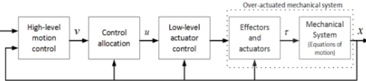
3.2 Weighted Pseudo-Inverse Control Allocation
The control allocation design is often divided into several levels as shown in Fig. 2.
For an octorotor UAV, the virtual control input v of the system will be the total thrust uf and the roll, pitch
and yaw moments τφ, τθ and τψ around the three axes,
computed according to the control laws to make the octorotor move as desired. The real control input is the motors speeds vector. The relation between these two vectors inputs is described by the control effectiveness matrix B, which depends on the octorotor configuration
and the rotors distribution. The low-level controller is the motors speed controller. In case of one or more actuators failures, the healthy actuators can be reconfigured by the control allocation system without having to change the motion controller structure and tuning.
The weighted pseudo-inverse method is often used to solve unconstrained linear control allocation problems. Neglecting any constraints and saturations on the input, an explicit solution for the control allocation problem can be obtained from the minimization of a quadratic problem as follows: min u J = ||W −1 u u|| s.t Bu(t) = τ (12) and the solution is given based on a weighted pseudo-inverse as follows:
u = [W BT(BW BT)−1] ∗ τ (13) where W = diag{w1· · · w8} represents the effectiveness
matrix of the individual rotors with 0 < wi < 1. τ =
[uf τφ τθ τψ]T is the virtual control inputs vector and
u = [ω2
1· · · ω82]T are the motors speeds. The fixed matrix
B is defined as: B = t1 · · · t8 r1 · · · r8 p1 · · · p8 y1 · · · y8 (14) with: ti= αij.Kf.S ri= dri.αij.Kf.S.l. √ 2/2 pi= dpi.αij.Kf.S.l. √ 2/2 yi = dyi.Kt (15)
ti, ri, piand yiare respectively the thrust and the torques
around the three axes produced by the actuator i. dri/pi/yi
is either 1 or −1 depending on whether the force created by the motor generates a positive or negative moment (see Eq. 4).
4. EXPERIMENTAL VALIDATION
In this section, the complete fault tolerance strategy is tested in real experiments on an octorotor UAV. Fault injection is used to simulate a motor failure, by sending commands to stop the failed motor at desired times. A propeller loss is simulated by detaching the propeller from its corresponding motor spindle before the flight.
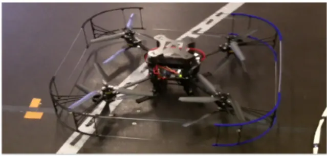
4.1 Experimental Platform
The experimental UAV is shown in Fig. 3. It is a coaxial octorotor built at the Heudiasyc laboratory. Its parameters are given in Table I.
Kf Thrust factor 3 ∗ 10−5N s2/rad2
Kt drag factor 7 ∗ 10−7N m/rad2
m mass of the vehicle 1.6 kg l length of the arm 0.23 m Ixx, Iyy Inertia 4.2 ∗ 10−2Kg.m2
Izz Inertia 7.5 ∗ 10−2Kg.m2
Table 1: The model’s parameters
Fig. 3. Experimental Octorotor 4.2 Results
Fault Detection and Isolation Two scenarios are pre-sented for the validation of the proposed FDI method: The first scenario consists of two simultaneous motors failures during the flight and the second consists of a propeller loss occurring before the take-off.
The SVM algorithm is implemented online on the UAV. The initialization phase is executed just one time before the take-off and it takes a few seconds. The prediction runs at the same frequency than the control law: 100 Hz. The speed threshold is set to 1300 rpm, a value that guarantees a fast detection while avoiding wrong decisions in a non-aggressive flight.
The results of the first scenario are shown in Fig. 4, 5 and 6 where motors 6 and 2 are stopped simultaneously when the octorotor was in a hovering flight. Figure 4 shows that, when the two motors are stopped at 29.18s, the real motor speeds no longer follow their references. If the difference rω = |ωMref − ωM| stays above the fixed threshold for a
period greater than 0.2s, a failed motor is identified and the SVM prediction phase is launched. Figure 5 shows the variations of the currents corresponding to the failed motors during the failures injection. Figure 6 shows that the SVM outputs are negative which corresponds to a motor failure. If rωexceeds the threshold for an amount of
time less than 0.2s, the system considers this discrepancy as abrupt changes caused by a sudden variation in the control law and no error is detected. The value 0.2 was empirically determined by previous experiments. Figure 6 reveals that the detection delay is 0.36s.
For the second scenario, the propeller is detached from the motor 4 spindle before the take-off. When the oc-torotor reaches a certain altitude, the detection module is launched at time 34.25s. Figures 7 and 8 show that the motor speed is very high while the current is almost zero. Based on these two observations, the SVM output is positive in Fig. 9 corresponding to a propeller loss. More satisfying validation scenarios (such as the ejection of a propeller during flight) were not carried out due to the complexity and amount of mechanical work needed for their implementations.
The main advantage that this method offers is the pos-sibility of detecting simultaneous faults (motor failure or propeller loss) since the state of each motor is evaluated separately from the others.
System Recovery Before injecting faults, the weighting matrix W ∈ R8x8is chosen as the identity matrix. Hence
Fig. 4. Motors speeds and their references during hovering flight when injecting total failures simultaneously on motors 6 and 2 at time 29.18s.
Fig. 5. Motors currents during hovering flight when inject-ing total failures simultaneously on motors 6 and 2 at time 29.18s.
Fig. 6. Diagnosis block output when injecting total failures simultaneously on motors 6 and 2. Motors failures are detected and isolated at time 29.54s.
Fig. 7. Speed of motor 4 while spinning without blades during a hovering flight.
The control allocation after the failure occurrence re-quires an information about this failure from the FDD module to reconfigure the weighting matrix online. Once a motor failure is detected, its corresponding weight wiis
set to zero.
After reaching its hovering attitude, failures are injected on motors 4 and 8 at times t4=29.41s and t8=36.24s
respectively as shown in Fig. 10. Figure 11 shows the outputs of the SVM algorithm. The first fault is injected on motor 4 at time t4= 29.4s and isolated at time t= 29.8s,
the second fault is injected on motor 8 at time t8= 36.24s
Fig. 8. Current of motor 4 while spinning without blades during a hovering flight.
Fig. 9. Diagnosis block output when motor 4 is spinning without blades during a hovering flight. The diagnosis module is activated at time 34.25s and gives a correct identification of the failure.
Fig. 10. Motors speeds and their references [rpm] during hovering flight when injecting total failures on motors 4 and 8.
and isolated at time t= 36.55s.
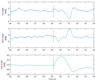
According to the outputs of the FDI module, the matrix W is reconfigured after 0.39s for motor 4 and 0.31s for motor 8. Figures 12 and 13 show respectively the attitude and the altitude of the octorotor before, during and after the faults injection. We can see that the system takes one or two seconds to recover completely from each failure and resumes its correct behavior after that. Similarly, when considering simultaneous motors failures, according to the outputs of the FDI module (see Fig. 6), the matrix W is reconfigured after 0.36 s. Figure 14 shows the attitude of the octorotor before, during and after the simultaneous failures.
5. CONCLUSIONS AND PERSPECTIVES This paper presents a complete fault-tolerant control strat-egy that allows a coaxial octorotor to maintain full con-trollability after losing one or more motors. The FDI uses a model-based analysis of the motors speeds to detect faults and identify the failed component, while a model-free clas-sification block distinguishes between motor failure and propeller loss. The recovery is based on the pseudo-inverse control allocation approach. Experimental validations are
Fig. 11. Diagnosis block output after injecting total failures on motors 4 and 8.
Fig. 12. Euler angles [deg] after injecting total failures on motors 4 and 8.
Fig. 13. Altitude [m] after injecting total failures on motors 4 and 8.
presented with good results with successive or simultane-ous motors failures.
In this paper, the same recovery strategy was used for both types of failures (motor failure or propeller loss) and the SVM algorithm was not used for the recovery of the system. In future works, we intend to study the effects of a rotating motor without propellers on the yaw torque, and consequently the effects on the applied recovery approach.
REFERENCES
Alwi, H. and Edwards, C. (2013). Fault tolerant control of an octorotor using lpv based sliding mode control allocation. In IEEE American Control Conference, 6505–6510. Washington, DC, USA.
Fig. 14. Euler angles [deg] after injecting simultaneous total failures on motors 6 and 2.
Alwi, H. and Edwards, C. (2015). Sliding mode fault-tolerant control of an octorotor using linear parameter varying-based schemes. IET Control Theory and Appli-cations, 9(4), 618–636.
Du, G.X., Quan, Q., and Cai, K.Y. (2015). Controllability analysis and degraded control for a class of hexacopters subject to rotor failures. Journal of Intelligent and Robotic Systems, 78(1), 143–157.
Lanzon, A., Freddi, A., and Longhi, S. (2012). Flight control of a quadrotor vehicle subsequent to a rotor failure. Journal of Guidance, Control, and Dynamics, 37(2), 580–591.
Lippiello, V., Ruggiero, F., and Serra, D. (2014). Emer-gency landing for a quadrotor in case of a propeller failure: A backstepping approach. In IEEE/RSJ Inter-national Conference on Intelligent Robots and Systems, 4782–4788. Chicago, IL, USA.
Marks, A., Whidborne, J.F., and Yamamoto, I. (2012). Control allocation for fault tolerant control of a vtol octorotor. In UKACC International Conference on Control, 357–362. Cardiff.
Merheb, A., Nourra, H., and Batemann, F. (2014). Active fault tolerant control of octorotor uav using dynamic control allocation. In International Conference on In-telligent Unmanned systems. Montreal, Canada. Saied, M., Lussier, B., Fantoni, I., Francis, C., and Shraim,
H. (2015a). Fault tolerant control for multiple successive failures in an octorotor: Architecture and experiments. In IEEE/RSJ International Conference on Intelligent Robots and Systems, 40–45. Humberg, Germany. Saied, M., Lussier, B., Fantoni, I., Francis, C., Shraim,
H., and Sanahuja, G. (2015b). Fault diagnosis and fault-tolerant control strategy for rotor failure in an octorotor. In International Conference on Robotics and Automation, 5266–5271. Washington, DC, USA. Schneider, T., Ducard, G., Rudin, K., and Strupler, P.
(2012). Fault-tolerant control allocation for multirotor helicopters using parametric programming. In Interna-tional Micro Air Vehicle Conference and Flight Compe-tition. Braunschweig, Germany.