HAL Id: insu-00617196
https://hal-insu.archives-ouvertes.fr/insu-00617196
Submitted on 26 Aug 2011
HAL is a multi-disciplinary open access
archive for the deposit and dissemination of
sci-entific research documents, whether they are
pub-lished or not. The documents may come from
teaching and research institutions in France or
abroad, or from public or private research centers.
L’archive ouverte pluridisciplinaire HAL, est
destinée au dépôt et à la diffusion de documents
scientifiques de niveau recherche, publiés ou non,
émanant des établissements d’enseignement et de
recherche français ou étrangers, des laboratoires
publics ou privés.
Coupling between hydrogeology and deformation of
mountainous rock slopes: Insights from La Clapière area
(southern Alps, France)
Yves Guglielmi, Frédéric Cappa, Stéphane Binet
To cite this version:
Yves Guglielmi, Frédéric Cappa, Stéphane Binet. Coupling between hydrogeology and deformation
of mountainous rock slopes: Insights from La Clapière area (southern Alps, France). Comptes
Ren-dus Géoscience, Elsevier Masson, 2005, 337 (13), pp.1154-1163. �10.1016/j.crte.2005.04.016�.
�insu-00617196�
Coupling between hydrogeology and deformation of mountainous
rock slopes: Insights from La Clapière area (southern Alps,
France)
Yves Guglielmi a,∗, Frédéric Cappa a, Stéphane Binet b
a UMR 6526 Géosciences Azur, CNRS–UNSA–IRD–UPMC, 06560 Sophia Antipolis, France b EA 2642 Géosciences, université de Franche-Comté, 25030 Besançon, France * Corresponding author.E-mail address: guglielmi@geoazur.unice.fr (Y. Guglielmi).
Abstract
Meteoric infiltration influence on large mountainous rock slopes stability is investigated by comparing hydrogeologic and gravitational structures from detailed mapping of the ‘La Clapière’ slope. The slope infiltrated waters are trapped in a perched aquifer that is contained in deposits inside tensile cracks of the upper part of the slope. Flow rates of 0.4 to 0.8 l s−1 from the perched aquifer to the landslide cause landslide accelerations. Numerical modeling shows that a 0.75 l s−1 infiltration yield increases conditions for toppling with failure through tilting of large rock volumes from the perched aquifer bottom down to the foot of the slope.
Keywords: Toppling; Hydromechanical coupling; Gravitational; Modelling; Long-term
1. Introduction
In the case of large gravitational mountainous rock slopes, water pressure elevation is one of the major factors triggering and increasing slope instability [15]. We address the problem of how to link localized hydromechanical (HM) effects with generalized slope destabilization, and to estimate what kind of infiltration event can produce sufficient HM non-reversible deformations [11]. First, the hydrogeology of the uncompressed zone that can extend deep in the slopes is not well known, except the fact that such a structural zone can allow high-yield groundwater flows parallel to the slope [13]. Second, couplings correspond to complex mechanisms. ‘Direct’ couplings occur through deformation and pore–fluid interactions and ‘indirect’ couplings imply changes in material properties [16]. It is obvious that such a detailed investigation is hard to conduct in large-scale dangerously moving media. We present in this paper a first attempt to analyse couplings between hydrogeology and stability, taking the example of the well-documented La Clapière landslide (France). Our study relies on a very detailed field mapping of geometrical relationships between hydraulic and gravitational structures of the slope and of time relationships between the current landslide velocities and precipitation. Then, a 2D HM numerical model is used to discuss our field results.
2. The La Clapière slope gravitational deformation
The La Clapière slope is situated at the northwestern edge of the Argentera–Mercantour metamorphic unit (Fig. 1). This basement unit underwent polyphased tectonic deformations during Variscan and Alpine orogeneses [9]. The foliation of the La Clapière slope dips gently (less than 20◦) either to the northeast or to the southwest [9]. Between 1700- and 2200-m elevations, metamorphic rocks are weathered in a zone from 50- to 200-m thick. Three sets of faults can be distinguished, trending N010◦E–N030◦E, N080◦E– N090◦E, and N110◦E–N140◦E, with nearly vertical dips (Fig. 1). The landslide rock mass (estimated volume about 60 million cubic metres) overlaps the Quaternary alluvial deposits of the Tinée River (Fig. 1a). At the top of the landslide is a 120-m-high scarp that extends over a width of 800 m at an elevation of 1600 m.
The landslide itself is divided into three main compartments, limited by pre-existing faults (Fig. 1b). Based on cross-sectional geometry, the depth of the failure surface may not exceed 100 to 200 m (Fig. 1c). The main central volume is bounded by the main failure surface. It moves downward at a velocity of 45 to 90 cm yr−1
towards directions N010◦E and N115◦E. The upper northeastern compartment (5-million- cubic-metre volume) behaves like a block landslide sliding along its own failure surface and overlapping the main landslide, with downward velocities of 100 and 380 cm yr−1. The upper northwestern compartment is bounded to the south by the 150-m-high scarp of the main landslide failure surface and to the north by a 50-m-high scarp. This compartment behaves like a fractured rock mass, with active tension cracks and velocities ranging from 20 to 70 cmyr−1. It is not certain that this compartment should be included in a failure surface at the present time. The presentday La Clapière landslide is nested in a larger unstable slope which has been active (Fig. 1). This unstable slope is characterized by extensional deformation structures like large tension cracks and several meters high downhill scarps located between 1700- and 2100-m elevations. These landforms involve displacements along penetrative pre-existing tectonic joints consistent with gravitational movements that could be linked to a general toppling of the upper part of large rock columns bounded by major penetrative faults. Tension cracks correspond to a metre-scale horizontal opening of the superficial part of the faults that induce a 10- to 50-m-deep trench.
Scarps correspond to shear displacements with a vertical throw ranging from 1 to 50 m. These movements occurred during three main pulses 11 000 years ago, 7000 years ago and 3000 years ago [3].
3. Gravitational deformations and slope hydrogeology
Three nested discontinuous fractured reservoirs characterize the slope hydrogeology. Water flows into fractures whose openings depend on the depth and on the gravitational structures of the slope. Gneisses can be considered as impervious [5]. The current landslide can be taken as a highly permeable fractured reservoir, because the displacements induce the formation of large pores inside opened fractures, breccias and blocks. The landslide is drained at its foot by a group of perennial springs (springs 14, 15, 16, 20 in Fig. 1a) with a total discharge comprised between 0.95 and 2.35 l s−1. The springs rise at the bottom of a major N010◦E-trending major fault zone that cuts the middle part of the main landslide. A perennial spring (spring 1) rises at the foot of the ortheastern compartment at elevation 1550 m, and has a discharge between 0.3 and 0.9 l s−1. After long precipitation periods, some temporary springs (springs T1 to T3) rise around 1550- to 1650-m elevation along faults or at the bottom of major tension cracks filled with colluvial deposits (spring T4). All the streams that originate from the springs located in the upper part of the landslide are interrupted a few hundred metres downstream. This means that all the waters reinfiltrate in the main landslide. Outside the landslide, the slope can be divided into a decompression toppled zone and a low uncompressed zone at depth. The decompression toppled zone is a highly fractured area where tension cracks create linear drains, with estimated permeabilities ranging between 10−2 and 10−3 ms−1 (permeability estimations are done from analytic interpretations of the yield variations of springs using Goodman’s formula [8]). Many of the cracks are filled with colluvial deposits, which constitute small reservoirs with an interstitial porosity. These tiny reservoirs are interconnected via the tension-crack network. It is possible to look in detail at colluvium filled tension-cracks, because some of them are cut by the present-day La Clapière main scarp (for location see black rectangle X near the spring T2 in Fig. 1a). Typically, the filling has a 4- to 20-m-wide triangular geometry and an average of 500-m length (Fig. 1c and d). It consists of blocks of various sizes whose arrangement defines rough bedding. The bedding is warped, showing that sedimentation occurred while gravitational movement was active. The deepest part of the filling often consists of very thin deposits of a buried soil that collapsed when the tensile crack was formed. Blocks and sands that can be found in the upper part of the deposits come from the fractured edges of the crack and from glacial deposits that previously covered the slope. The crack extends inside the slope, because it is the superficial reactivation of a tectonic fault. Depending on the places, the colluvial fillings can be completely dry or can be drained by a perennial spring (springs 3, 4 and 5 in Fig. 1a). In the first case, water infiltrating in the colluvial deposits is drained deeper in the slope through the underlying tectonic fault. In the second case, water is trapped in the filling because the basal buried soil is locally impervious. The interconnection of the fillings creates a perched perennial saturated zone that could explain the presence of springs in the upper part of the slope between 1650 and 1400 m in the Tinée Valley slope (springs 11 and 12 with a discharge ranging between 0.1 and 0.4 l s−1) and in the Rabuons Valley (springs 4, 5, and 6, with a discharge ranging between 0.1 and 0.6 l s−1). The low uncompressed part of the slope is outcropping on the Rabuons, the Tenibres and the Tinée River banks below the elevation 1400 m. This zone is fractured by major tectonic joints and can be considered as a relatively low-permeability fissured reservoir (10−8 to 10−9 ms−1, data from neighbouring tunnels inflows interpretation [13]). There is continuity between the joints and the tensile cracks mapped in the uncompressed toppled zone. No springs were mapped coming from this zone. In order to characterize long-term coupling between hydrology and stability of the slope, we compared historic records of Tinée River flooding (French Ministry of Agriculture database) to landslide annual velocities (French Ministry of Equipment database) since 1920 (Fig. 2a). The activation of the current La Clapière movement begins around the years 1950– 1955. From 1951 to 1987, there is a steady non-linear velocity increase up to a 6-m yr−1 peak. After 1987, there is a small decrease in velocities that show annual variations ranging between 4 and 2 myr−1. During the 1920–1999 period, there are Tinée major flood events corresponding to major precipitation events that caused numerous damages to the valley landscape. Clearly, La Clapière movement triggering fits with 1951–1957 major floods. However, 1922 and 1926 flood events did not cause any slope destabilization, and the 1987 velocity peak does not correspond with any major flood event. For the 1987 to the current period, speed fluctuations roughly fit with annual precipitation fluctuations [7]. At the year scale and for recent years (since 1998), a reconstitution was performed using hydrogeochemistry of spring waters [5]. Cappa et al. [5] show that the spring-water chemical signal presents transient changes occurring directly after precipitation events. From water chemical signal, the amounts of infiltration yields were inferred. There are two main infiltration peaks that correlate with longduration moderate precipitation amounts (for example, 426 mm/30 days during the 03/1999 period) or with short duration high precipitation amounts (for example, 122 mm/2 days during the 18–22/10/1999 period). For a 0.6-km2 infiltration
area, such amounts correspond to precipitation yields respectively ranging from 0.7 to 2.8 l s−1. Landslide velocity curves show accelerations that range from 0.02 to 0.25 mday−1 (Fig. 2b), synchronous with the infiltration peak periods. Velocity curves have an asymmetric shape with a rapid rise synchronous with the increasing part of the infiltration yield curve (main groundwater infiltration) and a slow decrease synchronous
with the decreasing and the drying-up part of the infiltration yield curve (slope drying-up). The duration of acceleration periods is about the same as for infiltration periods.
4. Modelling couplings
We performed two parametric simulations with the UDEC code [6] in order to estimate water infiltration influence during the initial 1951–1987 behaviour of the slope and during the current post-1987 seasonal behaviour of the slope. The UDEC numerical code calculates the bi-dimensional effects of stress on fluid flow, and allows conversely large finite displacements/ deformations of a fractured rock mass under pressure loading [6]. We considered a vertical crosssection oriented NE–SW, perpendicular to the topographic surface and extending from the slope crest (2600 m asl) to the Tinée Valley (1100 m asl). In the first test (Model A), only pre-existing fractures were taken into account (Fig. 3a). In the second test (Model B), a 28◦-dipping failure surface was set at the foot of the slope (Fig. 3b).We considered for both tests nine discrete penetrative vertical fractures that represent the major faults mapped on the site. So as to hydraulically connect faults between them and to approximate foliation plane geometry, horizontal joints were included in the model. The grid point is made up of triangular mesh elements whose sides are 100 m. This cross-section is constrained by no bottom vertical and no lateral displacements boundary conditions, and, by impervious hydraulic boundary conditions. Rock matrix mechanical behaviour is taken as linearly elastic and isotropic. Faults are assumed to behave according to an elasto-plastic law with the Mohr–Coulomb failure criterion (Table 1). Fault and matrix echanical and hydraulic parameters are deduced from laboratory and field measurements (Table 1) [5,10]. Parameters are the same for the two tests. The perched saturated zone is simulated, affecting a locally zero permeability at fault segments corresponding to the basal boundary of this zone (dashed line between 1500- and 2000-m elevation; Fig. 3). We performed a static hydromechanical calculation with steady-state flow without consideration of the time (only initial and final calculated equilibrium solutions are compared). The cross-section is first consolidated to gravity until stress and displacements are numerically stabilized (Stage 1). Second, initial groundwater conditions were simulated in the basal saturated zone (Stage 2). No interstitial pressure was set in the perched saturated zone. Then, a 0.75 l s−1 effective infiltration (this value is reported to the average length of a tensile crack reservoir, which is 500 m) is simulated in the slope at 1900-m elevation (Stage 3) (Fig. 3). On the cross-section, we plot maximum displacements induced by the hydraulic loading of Stage 3 (Fig. 3). These plotted displacements correspond to the end of the calculation when the hydromechanical state is stabilized. In the initial slope case (Model A, Fig. 3a), final calculated pressures are 1 MPa in the perched aquifer. In the basal aquifer, a 0.5-MPa piezometric bump extends from 300 to 1500 m along the xaxis. The maximum calculated values of displacement vector are located between the foot of the slope at 1100 m and the middle part of the slope at 1900 m. This strain zone extends from 50 to 400 m inside the slope. Displacements values vary between 0.1 m and 1.3 m in this zone. High water pressures compared to the hydrostatic pressures are situated in two distinct zones that hydraulically communicate with each other: a basal 500-m thick zone with interstitial pressures ranging between 0 and 5 MPa, and a perched 200-m thick zone with interstitial pressure ranging between 0 and 2-MPa. In the middle part of the slope, there is swelling with vectors dipping towards the top linked with mechanical opening of fractures under pressure increase in the perched saturated zone. In the upper part of the slope, there is a lowering generally called ‘sackung’ [1] with vertical vectors dipping.
The same results are observed in the current slope case (Model B, Fig. 3b). Pressure values are less important and the saturated zones are less extended inside the slope. This means that the slope is better drained after the failure has occurred, because the failure surface increased the connectivity of the previous fault network. As a matter of fact, displacement values are less important. Pressures along the failure plane range from 0 MPa at 1500 m to 0.05 MPa at 1150 m. Displacement maximum values of 0.4 to 0.6 m concentrate along the failure plane where vectors are parallel to the plane. However, a 0.1-m displacement zone extends further in the stable part of the slope, in relation with the basal piezometric bump hydromechanical effect. All the remaining of the slope is also affected by displacements values ranging between 0 and 0.05 m. These upper displacements belong to a deep displacement field generated by the slope foot sliding (mass loss).
The 35% differences between calculated (0.4 to 0.6 m) and measured (0.45 to 0.9 m) annual displacements for Model B can be explained in different ways: the non-consideration of 3D effects, the large heterogeneity of the medium that is highly simplified to a few major fracture planes, and the overestimation of infiltration yield. Such differences imply that caution needs to be exercised when using the results of such numerical models that only aim at a better understanding of the slope behaviour.
5. Discussion and conclusion
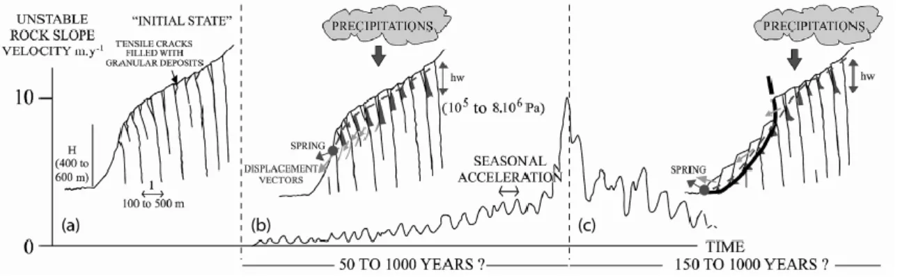
The current La Clapière landslide is ‘only’ one more reactivation of larger and older slope movements. The oldest known movement could have been triggered by the last deglaciation. Such initial movements correspond to large-scale toppling of the upper part of rock columns bounded by major vertical discontinuities of the slope (Fig. 4a). It has been shown at Séchilienne [18], Rosone [2], or more theoretically [12,14,17] that toppling can cause tensile crack opening in the upper part of a slope with ‘sackung’ and ‘swelling’, with the creation of
counter-ridges downslope. Deep inside the slope, failure can be initiated at the column base. We show in this study that tensile cracks are filled with local material of the slope and that they constitute perched reservoirs at the boundaries of the toppled columns. Hydrostatic pressures are concentrated in the middle and upper parts of the slope, where a relatively low infiltration yield (mean inter-annual value for example) can cause sufficient hydrostatic pressure increase in the cracks to increase rock column destabilization (Fig. 4b). Tilting at the column surface and failure propagation deep in the slope can be generated roughly from the theoretical bottom of the perched aquifer down to the slope foot. At La Clapière, such a failure through tilt could have worked until 1987, when it is thought [7,19] that a general failure surface was created. It could be still going on at Séchilienne and Rosone. When a major failure surface is generated, a large mass slides downslope (Fig. 4c). The slope drainage becomes more active through this failure surface, and there is a general lowering of the hydrostatic pressures in the slope. The perched aquifer is partly drained by the landslide, and, conversely, water coming from this aquifer imposes pressure increases in the upper segments of the landslide failure surface, which are closer to failure than the lower parts (where the stress state is high and the segment dip is low or 0). In regions with moderate seismicity, such typical rock slope gravitational structures [1,4], like ‘sackung’ at the top and ‘swelling or scarp’ at the foot, can then be activated in a few tens of years under precipitation-induced periodic hydromechanical effects. The main conducting parameters of the instability appear to be the slope angle and height, the dip and the spacing between the major penetrative discontinuities, previous gravitational history of the slope and hydrostatic pressures values in the perched aquifer.
Acknowledgements
The authors sincerely thank Dr Christopher Wibberley for his review and constructive comments. Contribution No. 661 of the ‘Géosciences Azur’ Lab.
References
[1] F. Agliardi, G. Crosta, A. Zanchi, Structural constraints on deep-seated slope deformation kinematics, Eng. Geol. 59 (2001) 83–102. [2] G. Barla, E. Chiriotti, Insights into the behaviour of the large deep seated gravitational slope deformation of Rosone, in the Piemont region (Italy), Felsbau 13 (1995) 425–432.
[3] F. Bigot-Cormier, R. Braucher, Y. Guglielmi, D.L. Bourlès, M. Dubar, J.-F. Stéphan, Chronological constraints of La Clapière landslide (44◦15N, 6◦56E, France): Geomorphology and cosmonuclide approaches, Geophys. Res. Abstr. 5 (2003) 12840.
[4] M.J. Bovis, S.G. Evans, Extensive deformations of rock slopes in southern Coast Mountains, southwest British Columbia, Eng. Geol. 44 (1996) 163–182.
[5] F. Cappa, Y. Guglielmi, V. Merrien-Soukatchoff, J. Mudry, C. Bertrand, A. Charmoille, Hydromechanical modeling of a large moving slope inferred from slope levelling coupled to spring long-term hydrochemical monitoring: example of La Clapière landslide (France, 06), J. Hydrol. 291 (2004) 67–90.
Y. Guglielmi et al. / C. R. Geoscience 337 (2005) 1154–1163 1163
[6] P.A. Cundall, A Generalized Distinct Element Program for modelling Jointed Rock, Peter Cundall Associates, US Army, European Research office, London Report PCAR-1–80, 1980.
[7] J.-P. Follacci, Les mouvements du versant de La Clapière à Saint-Étienne-de-Tinée (Alpes-Maritimes), Bull. Lab. Ponts et Chaussées 220 (150–151) (1987) 107–109.
[8] R.E. Goodman, D.G. Moye, A. Van Schalkwyk, I. Javandel, Ground water inflows during tunnel driving, Eng. Geol. 2 (1965) 39–56. [9] Y. Gunzburger, B. Laumonier, Origine tectonique du pli supportant le glissement de terrain de la Clapière (Nord-Ouest du massif de l’Argentera–Mercantour, Alpes du Sud, France) d’après l’analyse de la fracturation, C. R. Geoscience 334 (6) (2002) 415–422.
[10] Y. Gunzburger, Apports de l’analyse de la fracturation et de la modélisation numérique à l’étude du versant instable de la Clapière (Saint-Étienne-de-Tinée, Alpes-Maritimes), diplôme d’études approfondies, DEAPAE3S, Nancy, 2001, 82 p.
[11] Y. Guglielmi, J.-M. Vengeon, C. Bertrand, J. Mudry, J.-P. Follacci, A. Giraud, Hydrogeochemistry: an investigation tool to evaluate infiltration into large moving rock masses (case study of La Clapière and Séchilienne Alpine landslides), Bull. Eng. Geol. Environ. 61 (4) (2002) 311–324.
[12] E. Hoek, J.W. Bray, Rock Slope Engineering, The Institution of Mining and Metallurgy, London, 1981.
[13] J.-C. Maréchal, Les circulations d’eau dans les massifs cristallins alpins et leurs relations avec les ouvrages souterrains, PhD thesis n◦1769, École polytechnique fédérale de Lausanne, Switzerland, 1998, 298 p.
[14] V. Merrien-Soukatchoff, X. Quenot, Y. Guglielmi, Modélisation par éléments distincts du phénomène de fauchage gravitaire. Application au glissement de La Clapière (Saint-Étienne de- Tinée, Alpes-Maritimes), Rev. Fr. Géotech. 95–96 (2001) 133–142.
[15] F. Noverraz, C. Bonnard, H. Dupraz, L. Huguenin, Grands glissements de versants et climat, Rapport final PNR 31, VDF Hochschuleverlag AG an der ETH Zürich, Switzerland, 1998.
[16] J. Rutqvist, O. Stephanson, The role of hydromechanical coupling in fractured rock engineering, Hydrogeol. J. 11 (2003) 7–40. [17] C. Sagaseta, J.M. Sanchez, J. Canizal, A general analytical solution for the required anchor force in rock slopes with toppling failure, Int. J. Rock Mech. Min. Sci. 38 (2001) 421–435.
[18] J.-M. Vengeon, Déformation et rupture des versants en terrain métamorphique anisotrope, PhD thesis, University Joseph- Fourier– Grenoble-1, France, 1998, 186 p.
[19] C. Vibert, Apport de l’auscultation de versants instables à l’analyse de leur comportement, les glissements de Lax-le- Roustit (Aveyron) et Saint-Étienne-de-Tinée, France, PhD thesis, École des mines de Paris, 1987.
TABLES AND FIGURES
Fig. 1. (a) Geostructural, hydrological and landslide context, (b) landslide compartments, (c) hydrogeological cross section, (d) field observation of a tensile crack filled with superficial deposits.
Fig. 2. (a) Long-term comparison between La Clapière landslide velocity and Tinée River major flood events (after [7], modified); (b) Correlation between infiltration and velocity variations at the year scale.
Fig. 3. Results of coupled hydromechanical modelling: (a) Model ‘A’, only with pre-existing faults; (b) Model ‘B’, with pre-existing faults and a 28◦-dipping failure surface.