Publisher’s version / Version de l'éditeur:
Canadian Geotechnical Journal, 16, 1, pp. 233-235, 1979-02
READ THESE TERMS AND CONDITIONS CAREFULLY BEFORE USING THIS WEBSITE. https://nrc-publications.canada.ca/eng/copyright
Vous avez des questions? Nous pouvons vous aider. Pour communiquer directement avec un auteur, consultez la
première page de la revue dans laquelle son article a été publié afin de trouver ses coordonnées. Si vous n’arrivez pas à les repérer, communiquez avec nous à [email protected].
Questions? Contact the NRC Publications Archive team at
[email protected]. If you wish to email the authors directly, please see the first page of the publication for their contact information.
NRC Publications Archive
Archives des publications du CNRC
This publication could be one of several versions: author’s original, accepted manuscript or the publisher’s version. / La version de cette publication peut être l’une des suivantes : la version prépublication de l’auteur, la version acceptée du manuscrit ou la version de l’éditeur.
Access and use of this website and the material on it are subject to the Terms and Conditions set forth at
The bellow-hose settlement gauge
Bozozuk, M.; Fellenius, B. H.
https://publications-cnrc.canada.ca/fra/droits
L’accès à ce site Web et l’utilisation de son contenu sont assujettis aux conditions présentées dans le site LISEZ CES CONDITIONS ATTENTIVEMENT AVANT D’UTILISER CE SITE WEB.
NRC Publications Record / Notice d'Archives des publications de CNRC:
https://nrc-publications.canada.ca/eng/view/object/?id=4642910d-3f78-4240-9fb2-d0e8a3adf812 https://publications-cnrc.canada.ca/fra/voir/objet/?id=4642910d-3f78-4240-9fb2-d0e8a3adf812
ational Research Conseil national Council Canada de recherches Canada
THE BELLOW-HOSE SETTLEMENT
GAUGE
by M. Bozozuk and B. H. Fellenius
e
Reprinted from
Canadian Geotechnical Journal Vol. 16, No. 1, February 1979 p. 233-235
DBR Paper No. 830
Division of Building Research
This publication is being distributed by the Division of Building Research of the National Research Council of Canada. It should not be reproduced in whole or in part without permission of the original publisher. The Division would be glad to be of assistance in obtaining such permission.
Publications of the Division may be obtained by mailing the appropriate remittance (a Bank, Express, or Post Office Money Order, or a cheque, made payable to the Receiver General of Canada, credit NRC) to the National Research Council of Canada, Ottawa KIA OR6. Stamps are not acceptable.
A list of all publications of the Division is available and may be obtained from the Publications Section, Division of ~ u i l d i n ~ Research. National Research Council of Canada. Ottawa
The bellow-hose settlement gauge
M. Bozozu~Geotechnical Section, Division of Building Research, National Research Council of Canada, Ottawa, Ont., Canada K I A OR6 AND
B. H. FELLENIUS~
Terratech Ltd., Montreal, P.Q., Canada H4N IJl Received May 17, 1978
Accepted September 29. 1978
Bellow-hose settlement gauges were used to measure vertical soil heave during the installation of concrete piles in sensitive marine clay. The equipment is described and the sources of error are discussed.
Des tassomktres lt tube compressible ont tt6 utilises pour mesurer les soulkvements verticaux du sol lors de l'installation de pieux de beton dans une argile marine sensible. On dkrit l'equipe- ment et on discute les causes d'erreurs. [Traduit par la revue]
Can. Geotech. J., 16, 233-235 (1979)
Introduction
Several thousand end-bearing concrete piles, re- quired for the expansion of a large industrial plant in eastern Canada, were to be driven through sensitive marine clay. To study how adjacent foundations are affected by driving a large group of piles, a research I program was initiated to measure the soil and pile
'Present address: BHF Consultants Inc., Montreal, P.Q.,
Canada H9A 1 W9.
movements on a selected group of 116 piles (Bozozuk
et al. 1978). This note describes the bellow-hose
settlement gauge used to measure the vertical soil movements as the pile driving program was carried out.
Bellow-hose Gauge
The bellow-hose settlement gauge is similar to that developed by Wager (1973). It consists of a spirally reinforced axially flexible polyethylene tube 40 mm
0008-3674/79/010233-03$01.00/0
234 CAN. GEOTECH. J. VOL. 16. 1979
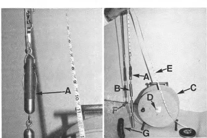
FIG. 1. Components of bellow-hose settlement gauge: A = electric probe with flexible spring contacts; B = gauge
weights (3 X 500 g); C = reel; D = voltmeter; E = measuring tape (in inches); F = electric connecting cable; and G = sample of axially compressible bellow-hose. (Photos: B. H. Fellenius, Terratech Ltd., Montreal.)
in diameter, equipped with 50 mm long, 25 mm inside diameter metal rings mounted at predetermined locations to serve as measuring points.
To install the gauge, a 60 mm diameter casing is first placed to the desired depth. In soft soils, the bottom of the casing is plugged and pushed down; in stiff soils, the casing is drilled and washed, care being taken that the surrounding soil is not overwashed, which would create voids around and underneath it. The bellow-hose is filled with water, a 10 mm grout- ing hose is loosely attached to the bottom end, and both are lowered into the casing. A 20 mm diameter iron pipe is then inserted to the full length of the bellow-hose and secured at the top to stabilize and support the installation during grouting.
A bentonite-cement grout consisting of one part Portland cement and four parts bentonite at a water content of 350y0 is pumped through the grout hose to fill the void between the bellow-hose and the soil. The casing and the grout hose are withdrawn simul- taneously and gradually, taking care to ensure that the grout level is always above the bottom of the casing and the tip of the grout hose. Finally, the top of the bellow-hose is secured to a 1.8 m length of
protective casing and grouted to the soil at the ground surface; then the 20 mm diameter iron pipe is withdrawn.
The elevations of the measuring rings are deter- mined by means of an electric probe attached to a measuring tape (Fig. 1). The probe consists of a 100 mm long, 20 mm outside diameter plastic body connected to three spool-shaped steel 500 g weights that hang from it. Three equally spaced arch-shaped steel springs 30 mm long protrude about 5 mm from the side of the probe. The steel springs are electrically insulated from each other, but two of them are con- nected to a cable leading from the probe to a volt- meter. When the probe contacts the metal rings, the electric circuit is closed, activating the voltmeter. The cables and the measuring tape are coiled together on a drum from which they are fed into the bellow-hose. Measurements can be made by one man. The measur- ing time for a gauge 18 m deep with contact rings installed at 2 m intervals of depth is about 20 min. Measurements are performed by first lowering the probe to the bottom of the hose and then lifting it up to contact each ring in turn, and recording the dis- tance to the top of the settlement gauge. The eleva-
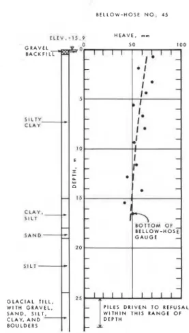
NOTES 235 B E L L O W - H O S E N O . 4 5 I t t V . - l S . P H E A V E . rnm G L A C I A L T I L L , W I T H G R A V E L , S A N D . S I L T , C L A Y , A N D B O U L D E R S P I L E S D R I V E N T O R E F U S A L W I T H I N T H I S R A N G E O F
I
.EPT.FIG. 2. Variation of measured soil heave with depth within group of driven piles.
tions of the rings are obtained from the elevation of the top of the gauge, which was determined from level surveys.
A number of factors affect the accuracy of the measurements. The direct reading error has been established by repeated measurements to be a maxi- mum of f 2 mm. In connection with pile driving, however, horizontal soil movements occurred that caused the metal rings to tilt. The three steel springs eliminated most of this error, but additional in- accuracy appeared. Including the effect of weather, time, etc., on human performance, the actual com- bined error was about +5 mm. When errors inherent in level surveying to the gauges were added, the possible total error increased to about +8mm.
Survey errors can, however, be reduced either by anchoring the bottom of the bellow-hose in firm soil not subject to soil movements, or by installing a deep bench mark directly outside the bellow-hose gauge. Figure 2 shows the variation of measured heave to a depth of 16.5 m after driving a group of 116 con- crete piles around an installation in marine clay. The deviation of the measured values from the average line are within +8mm, the stated accuracy of the gauge.
Summary and Conclusions
The bellow-hose settlement gauge proved to be a useful field instrument for measuring the variation of soil heave with depth at a given location. It has an accuracy of f 2 mm if installed in a soil not subjected to horizontal soil movements and with its lower end seated in a firm soil formation. In the present case, however, the soil was subjected to horizontal move- ments that caused the measuring rings to tilt, and the position of the bottom of the bellow-hose was affected by the pile driving. Level surveys were required to establish a datum elevation for each set of measurements. The resultant combined error increased to f 8 mm.
The advantage of this equipment is that vertical soil movements can be measured at numerous prede- termined elevations quickly and easily at one in- stallation.
Acknowledgements
The work was carried out by Terratech Ltd., under Contract No. OSR4-0135 of the Department of Supply and Services, Canada. The assistance of Mr. D. Marcil, President of Roctest Limited, whose firm manufactured the bellow-hose settlement gauge, is greatly appreciated.
This paper is a joint contribution from Terratech Ltd. and the Division of Building Research, National Research Council of Canada.
B o w z u ~ , M., FELLENIUS, B. H., and SAMSON, L. 1978. Soil disturbance from pile driving in sensitive clay. Canadian Geotechnical Journal, 15(3), pp. 346-361.
WAGER, 0. 1973. Balgsftttningsmatare for matning av vertikal- rorelser i jord. Lecture at the Nordic Geotechnical Meeting, Trondheim in The Norwegian Geotechnical Society Report, Oslo, Norway, pp. 95-98. (In Swedish.)