Publisher’s version / Version de l'éditeur:
Building Practice Note, 1985-10-01
READ THESE TERMS AND CONDITIONS CAREFULLY BEFORE USING THIS WEBSITE.
https://nrc-publications.canada.ca/eng/copyright
Vous avez des questions? Nous pouvons vous aider. Pour communiquer directement avec un auteur, consultez la première page de la revue dans laquelle son article a été publié afin de trouver ses coordonnées. Si vous n’arrivez pas à les repérer, communiquez avec nous à [email protected].
Questions? Contact the NRC Publications Archive team at
[email protected]. If you wish to email the authors directly, please see the first page of the publication for their contact information.
NRC Publications Archive
Archives des publications du CNRC
For the publisher’s version, please access the DOI link below./ Pour consulter la version de l’éditeur, utilisez le lien DOI ci-dessous.
https://doi.org/10.4224/20375156
Access and use of this website and the material on it are subject to the Terms and Conditions set forth at
The ventilation of insulated roofs
Forgues, Y. E.
https://publications-cnrc.canada.ca/fra/droits
L’accès à ce site Web et l’utilisation de son contenu sont assujettis aux conditions présentées dans le site LISEZ CES CONDITIONS ATTENTIVEMENT AVANT D’UTILISER CE SITE WEB.
NRC Publications Record / Notice d'Archives des publications de CNRC:
https://nrc-publications.canada.ca/eng/view/object/?id=33c9cd5e-982f-4beb-84e9-50002ce26c1f https://publications-cnrc.canada.ca/fra/voir/objet/?id=33c9cd5e-982f-4beb-84e9-50002ce26c1f
THE VENTILATION OF IhTSULATED ROOFS
zyxwvutsrqponmlkjihgfedcbaZYXWVUTSRQPONMLKJIHGFEDCBA
by
Y.E.
ForguesTechnical Information Section Division of Building Research
BPN 57
Ottawa, October 1985
@National Research Council Canada 1985
TABLE O F CONTENTS
ABSTRACT/RESUME
zyxwvutsrqponmlkjihgfedcbaZYXWVUTSRQPONMLKJIHGFEDCBA
. . .
1INTRODUCTION
. . .
zyxwvutsrqponmlkjihgfedcbaZYXWVUTSRQPONMLKJIHGFEDCBA
2 SOURCES O F MOISTTJRE. . .
2PROBLEMS DUE T O EXCESSIVE MOISTURE IN ROOF SPACES
. . .
4zyxwvutsrqponmlkjihgfedcbaZYXWVUTSRQPONMLKJIHGFEDCBA
VENTILATION O F ROOF SPACES. . .
4TYPES OF R.OOF SPACES
. . .
6TYPES OF ROOF VENTS
. . .
7VENTILATION O F MANSARD ROOFS
. . .
11RETROFITTING AND VENTILATION
. . .
11CONCLUSION
. . .
12REFERENCES
. . .
13ABSTRACT
zyxwvutsrqponmlkjihgfedcbaZYXWVUTSRQPONMLKJIHGFEDCBA
Although roof space ventilation may not. be very effect,ive in cold weather, it is required as the outside air warms up, to dry out moisture that may have accumulated in the roof space. This Xote stresses the importance of reducing the movement of moisture from the living areas to the roof space and of ventilating the latter by means of vents distributed between the upper and lower parts of the roof to take advantage of both wind action and stack action.
RESUME
La ventilation des toitures, quoique peu efficace en hiver, permet, par temps chaud, d’asskcher les condensations qui ont pu s’y accumuler par temps froid. L a prCsente Note traite de l’importance de rkduire au minimum le transport d’humiditk de l’habitat a l’entretoit et de ventiler ce dernier au moyen d’orifices de ventilation rkpartis en parties infkrieure et sup6rieure afin de tirer avantage aussi bien de l’action du vent que du tirage thermique.
INTRODUCTION
zyxwvutsrqponmlkjihgfedcbaZYXWVUTSRQPONMLKJIHGFEDCBA
The oil crisis of 1973 has led to improvements in the thermal efficiency of buildings in an effort to conserve energy. One energy-saving technique has been to reduce air leakage through the building envelope: another has been to add insulation in the roof space. The resulting higher interior humidities and colder attic temperatures have increased the potential for condensation in roof spaces in cold weather. To reduce condensation) these spaces must be properly ventilated, and the ceiling below them made sufficiently airtight. Ventilating the roof space provides a cooler attic
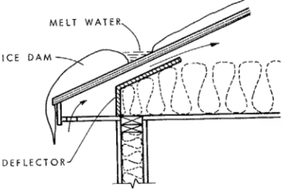
in hot weather and helps to dissipate the mois- ture that may have accumulated in cold weather. If combined with more airtight ceilings and re- duced heat loss from added insulation) ventila- tion may also help to prevent the formation of ice dams along the eaves of sloped roofs, which
often results from warm roof spaces (Figure 1).
zyxwvutsrqponmlkjihgfedcbaZYXWVUTSRQPONMLKJIHGFEDCBA
M E L T W A T E R ICE D A M
D E F L E C T
Figure 1. Ice dam prevention
During very cold weather, outside air absorbs very little moisture. Most of the moisture that finds its way into the roof space will condense out of the air when it comes in contact with the cold sheathing. Cold air circulating in an attic is not effective in removing condensation because of its low capacity for moisture absorption. Most Canadian houses will probably have some accumulation of condensation or frost in the attic during the winter. As the outside air gets warmer in late winter: its capacity to absorb moisture increases and drying conditions improve. Even during cold weather) the combined effect of solar radiation and heat loss from the building increases the temperature of the air in the roof space, allowing some moist.ure to be removed.
Although ventilation may not be entirely effective in removing condensation in cold weather) it is required as t,he outside air warms up to dry out moisture that may have accumulated during colder periods.
SOURCES OF MOISTURE
Moisture is transferred from the living areas into the roof space by diffusion due to a
difference in water vapour pressure) and by air leakage resulting from an air pressure difference due to wind action or “stack action’) (Figs. 2a,2b).
When warm air from the living areas flows into a cold roof space, it is cooled and its ability tmo hold water is reduced. If the temperature of this air falls below its dew point,, condensation will occur. If warm interior air at,, say, 20°C and 40% relative humidity is
c ) C H I M N E Y A N D
E X H A U S T F A N S
zyxwvutsrqponmlkjihgfedcbaZYXWVUTSRQPONMLKJIHGFEDCBA
a ) W I N D A C T I O N b ) S T A C K A C T I O NzyxwvutsrqponmlkjihgfedcbaZYXWVUTSRQPONMLKJIHGFEDCBA
Figure 2.
zyxwvutsrqponmlkjihgfedcbaZYXWVUTSRQPONMLKJIHGFEDCBA
Pressure diagrams for housescooled down to 6"C, its relative humidity will increase to 100%; i.e., the point of saturation. If it is cooled below 6"C, condensat,ion will take p1a.c.e.
To reduce the amount of moisture entering the roof space and condensing, one must first reduce the amount of moisture produced in the living areas. The main sources of wa- ter vapour include cooking, baths and showers, laundry. unvented combustion appliances, house plants and green firewood. The occupants also generate significant quantities of moisture through breathing and perspiration. Since electrical heating requires no combus- tion air and no flue, the relative humidity in homes heated electrically tends t o be higher than in those heated with oil, gas or wood.
Exhaust fans in high-moisture areas such as bathrooms, laundry rooms and kitchens can be used to remove excess moisture. Although not energy-efficient, they are effective. The flow of water vapour through a material by diffusion varies in proportion to the difference in vapour pressure across the material and the permeability of the material. The higher the quantity of water vapour in the air a t a given temperature, the higher the vapour pressure. If the vapour pressure is higher in the living areas than in the adjacent roof space, moisture will diffuse through the ceiling assembly into the roof space. Such diffusion, however, normally accounts for only a small fraction of the total.
Most moisture enters the roof space as a result of air leakage 111. Air from the living areas can leak into adjacent roof spaces through many paths; for example, chimneys, vent pipes, electrical wiring and other services. Interior partitions can provide additional paths as
a result of holes for electrical wiring, of gaps between the wall finish and framing due to wood shrinkage. and of cracks caused by the deflection of floors and ceilings and differential settling of the foundations. The amount of water vapour transported by leakage is hard to determine. The total cross-sectional area of the leakage paths and the pressure differences existing between the two sides of a ceiling are generally not well-known and are difficult to measure [2].
Chimneys and mechanical exhaust, syst,ems can also affect the amount of ,air leakage into
or even prevent the flow of air from the living areas into the roof space (Figure 2c). Tests
on a two-storey house have shown that a chimney can reduce air leakage through the ceiling
of the second storey by almost
zyxwvutsrqponmlkjihgfedcbaZYXWVUTSRQPONMLKJIHGFEDCBA
40% ;3].Access hatches to attic.s are potential sources of air leakage, but can be sealed using gaskets. Exha.ust d u c k from bathrooms and kitchens can also cause serious condensation problems in roof' spaces. They should have airtight joints, both within the roof space and at. the ceiling where they enter the attic space. It, is important that such ducts extend to the outside and not terminate within the roof space.
PROBLEMS DUE TO EXCESSIVE MOISTURE IN ROOF SPACES
Both condensation of air from the living areas and water leaking into the roof space from outside can cause excessive moisture. If this moistmure is not removed within a reasonable time, wood decay may set in and roof truss connector plates may corrode. In addition, moisture will cause panel-type roof sheathing to expand to the point of buckling, and will reduce the thermal resistance of insulation materials.
Visible symptoms of excessive moisture, whether from condensation or from leaks in the roof, are water staining, cracking, paint failure and other forms of deterioration of the ceiling.
Moisture diffusion from the living areas into the roof space can be reduced effectively by installing a waterproof membrane such as polyethylene film between the ceiling finish and the insulation; however, moisture migration due to air leakage is more difficult to control. Although the vapour barrier helps to make the ceiling assembly more airtight, it is difficult to seal all possible air leakage paths between the living areas and the roof space.
A ceiling finish such as drywall can substantially reduce air leakage if it is made airtight over the entire house. To increase the effectiveness of drywall, all openings in it must be sealed. Placing electrical outlet boxes and other services elsewhere than in the ceiling will also reduce air leakage.
VENTILATION OF ROOF SPACES
Roof spaces can be ventilated either by natural or by mechanical means.
Wind causes positive pressures on the windward side and negative pressures on the leeward side of buildings; as a result, outside air is drawn into the roof space in zones of positive
pressure, and expelled in zones of negative pressure (Figs. 3 and 4).
zyxwvutsrqponmlkjihgfedcbaZYXWVUTSRQPONMLKJIHGFEDCBA
The ra.te of air change\
S T E E P S L O P E M O D E R A T E S L O P E
zyxwvutsrqponmlkjihgfedcbaZYXWVUTSRQPONMLKJIHGFEDCBA
Figure
zyxwvutsrqponmlkjihgfedcbaZYXWVUTSRQPONMLKJIHGFEDCBA
3.zyxwvutsrqponmlkjihgfedcbaZYXWVUTSRQPONMLKJIHGFEDCBA
Approximate distribution of pressures due to winda ) A T T I C - T Y P E ROOF b ) C A T H E D R A L - T Y P E ROOF
Figure
zyxwvutsrqponmlkjihgfedcbaZYXWVUTSRQPONMLKJIHGFEDCBA
4. Types of roof spacesNatural ventilation can also result from stack action. As air becomes warmer, its density decreases, giving it a tendency to rise. On a sunny day the temperature inside a roof space will generally be higher than that outside due to solar radiation and, t o a lesser degree, to heat gain from the living areas. This heated air will tend to rise towards the upper part of the attic. Air changes through stack action are facilitated by air intake openings in the lower part of the attic and exhaust openings in the upper part. Unlike ventilation through wind action, ventilation through stack action is more constant, depending only on the difference in temperature between the outside air and the roof space, and on the vertical distance between the intake and exhaust openings. The natural ventilation of a
roof space is opt,imized if one can make use of both stack and wind action.
zyxwvutsrqponmlkjihgfedcbaZYXWVUTSRQPONMLKJIHGFEDCBA
0 Using fans to improve roof space ventilation will also help to cool the living area in hot
of humid air leaking through the ceiling. In cold weather, the increased leakage will in turn weather [2]. However, the negative pressure created by exhaust fans increases the amount lead to increased condensation. The benefits of mechanical ventilation must be weighed against costs due to installation, maintenance. repair and operation.
1
zyxwvutsrqponmlkjihgfedcbaZYXWVUTSRQPONMLKJIHGFEDCBA
N
TYPES OF ROOF SPACES
zyxwvutsrqponmlkjihgfedcbaZYXWVUTSRQPONMLKJIHGFEDCBA
If the framing members supporting the roof deck do not also support the ceiling, the roof space or attic is usually fairly large and can be ventilated easily (Figure 4a). If they also support the ceiling, the resulting roof space is usually fairly small and is more difficult to ventilate, particularly when it is well insulated. Such is the case for flat roofs and cathedral-type roofs (Figure 4b). Ventilation requirements for the latter are, therefore, greater than for the more common attic-type roofs.
Where the roof space is fairly large (i.e., attic spaces with roof slopes greater than 1:6),
the total net vent area should be at least 1/300th of the area of insulated ceiling. These vents can be located in the soffit, in gable walls, in the roof surface or at several of these locations, but should be distributed so as to provide effective cross-ventilation 141.
For flat or low-sloped roofs
zyxwvutsrqponmlkjihgfedcbaZYXWVUTSRQPONMLKJIHGFEDCBA
(1:6 or less), and cathedral ceilings, the total net vent areaneeds to be twice as large; i.e., 1/150th of the area of the insulated ceiling. A low roof slope decreases the amount of ventilation that can be achieved through stack action, and the presence of large quantities of insulation often restricts the ventilation space between the insulation and the roof Sheathing. In such roofs, moisture will tend to condense on the cold surfaces of the sheathing and framing members because it cannot dissipate over
a large area, as it can in attic roofs.
Ventilation of flat roofs or roofs with cathedral ceilings can be improved by installing
purlins of at least 38
zyxwvutsrqponmlkjihgfedcbaZYXWVUTSRQPONMLKJIHGFEDCBA
x 38 mm at right angles to the roof joists. In addition, the topsurface of the insulating material should be at least 25 mm below the top of the roof joists (Figure 5). This arrangement makes it possible for wind coming from any direction t o ventilate the roof space, provided that roof vents are installed on all exposed sides.
2 5 MI RLINS..
zyxwvutsrqponmlkjihgfedcbaZYXWVUTSRQPONMLKJIHGFEDCBA
x 3 8 m m \ ROOF\;-
' IzyxwvutsrqponmlkjihgfedcbaZYXWVUTSRQPONMLKJIHGFEDCBA
\ ' , I J O I S T S I : \ : ' , I : --,,zyxwvutsrqponmlkjihgfedcbaZYXWVUTSRQPONMLKJIHGFEDCBA
IFigure 5 . Flat roof or cathedral roof (slope less than 1:6)
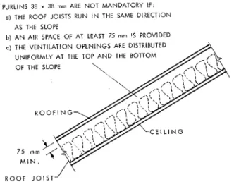
However, purlins may not be necessary if the roof slope is 1:6 or more, provided that the roof framing members run in the same direction as the roof slope and that a minimum clearance of 75 mm is maintained between the roof sheathing and the top of the insulation.
PUKLINS 38
zyxwvutsrqponmlkjihgfedcbaZYXWVUTSRQPONMLKJIHGFEDCBA
x 38zyxwvutsrqponmlkjihgfedcbaZYXWVUTSRQPONMLKJIHGFEDCBA
m m ARE N O T MANDATORY I F .a) THE ROOF JOISTS RUN IN THE SAME DIRECTION
zyxwvutsrqponmlkjihgfedcbaZYXWVUTSRQPONMLKJIHGFEDCBA
c ) THE VENTILATION OPENINGS ARE DISTRIBUTEDzyxwvutsrqponmlkjihgfedcbaZYXWVUTSRQPONMLKJIHGFEDCBA
In such roofs (Figure 6) the vents should be distributed so as to provide a t least half of the required ventilation in the lower part of the roof and half near the ridge.
AS THE SLOPE
b) A N AIR SPACE OF AT LEAST 75 inn1
zyxwvutsrqponmlkjihgfedcbaZYXWVUTSRQPONMLKJIHGFEDCBA
‘ 5 PROVIDED UNIFORMLY AT THE TOP A N D THE BOTTOMOF THE SLOPE \ ‘ . .., \ R O O F I N G 1 R O O F J O I S T - ’
zyxwvutsrqponmlkjihgfedcbaZYXWVUTSRQPONMLKJIHGFEDCBA
Figure 6. Cathedral-type roof (slope of 1:6 or more)
In highly insula.ted flat roofs and cathedral-type roo-.-, the clzpth of conventional roof framing may not provide sufficient, ventilation space between the insulation a.nd the roof sheathing. Using parallel chord trusses can provide additional space. Their greater depth and open webs facilitate air movement through the roof space (Figure 7 ) .
roofs or
Because the small roof spaces in flat roofs and cathedral ceilings make it practically im- possible to inspect the condition of the framing members and the decking, it is particularly important t o reduce air leakage through the ceiling to an absolute minimum and provide the most effective ventilation possible when building these roofs.
TYPES OF ROOF VENTS
Roof spaces may be ventilated by soffit vents, roof vents, ridge vents, and gable vents used in various combinations. All of these vents must be designed to prevent the entry of rain, snow and insects. In addition, the net area of such vents should be known in order to determine the total vent area required. A standard that describes vent design and area is available
[
51.!i
i
Soffit vents installed along the underside of the roof overhang may be continuous or may consist of indi- vidual, spaced vents. Perforated soffits made from metal, plastic or wood are also available. Soffit ven- tilation enables air to flow easily through the roof space for all wind directions. Combining soffit vents with vents in the upper part of the roof will further increase ventilation (Figure 8).
4
zyxwvutsrqponmlkjihgfedcbaZYXWVUTSRQPONMLKJIHGFEDCBA
Figure 8. Soffit vents
The passage of air from the soffit to the attic should not. be restricted by insulation. Deflectors should be installed where necessary above the exterior wall to maintain a space, between the insulation and the roof deck, of a t least the same cross-sectional area as the soffit vent area (Figure 1).
Vents located in the roof surface near the ridge improve ventilation when used in combi- nation with soffit vents (Figure 9 ) . If they are used alone, only a relatively small volume
of air within the immediate area of the vents will be displaced. Since the net area of these roof sur-
face vents is only between 250 and 500 cm’, it is impractical in most cases to install enough of them to provide the total required vent area. Providing for the distribution of vents between soffit and roof is therefore a more effective solution.
Figure 9. Soffit plus roof vents Figure 10 represents an example of a roof with two slopes, one of which is equipped wit,h three roof surface vents. Figure 11 illustrates a roof with four slopes in which a triangular vent, often used as a gable wall vent, has been installed.
Figure 10. Roof vents near the ridge of a
ga.ble roof
Figure 11. Triangular vent near the ridge
Turbine vents are usually installed near the upper part of the roof. They consist of a rotating assembly of wind-driven helicoidal blades which draws air from the roof space. If suction is created inside the roof space because of insufficient air supply from the out- side, additional moisture may be drawn from the living areas, thereby aggravating the condensation problem.
Gable vents are usually more effective than roof surface vents. The volume of air moved by this type of vent depends on the direction and speed of the wind. If the wind is
perpendicular to the ridge, only air in the immediate vicinity of the gables will be moved.
zyxwvutsrqponmlkjihgfedcbaZYXWVUTSRQPONMLKJIHGFEDCBA
A wind direction parallel to the ridge will move the air in through one gable and out through the other, resulting in a large volume of displaced air. TJsing gable vents in combination with soffit vents will improve air circulation in the lower part of the roof (Figure 12). Gable vents have a series of blades sloped at 45". If not properly designed, they may allow rain or
snow to enter the roof space. A rectangular-type gable vent equipped with blades angled
at
zyxwvutsrqponmlkjihgfedcbaZYXWVUTSRQPONMLKJIHGFEDCBA
45" is shown in Figure 13.Figure
zyxwvutsrqponmlkjihgfedcbaZYXWVUTSRQPONMLKJIHGFEDCBA
12. Soffit plus gable vents Figure 13. Rectangular vent in a gableroof
In regions such as the Prairies, which are subject to fine, wind-driven snow, gable vents may have to be closed in winter to prevent snow from accumulating in attics.
The most efficient venting system uses both continuous ridge vents and soffit vents. This system enables even and continuous ventilation of the attic by combining wind action and stack action. Ridge vents have continuous openings along the ridge (Figure 14). Their loca- tion in a zone of negative pressure allows them t o act as air exhaust openings for all wind directions. If, however, alternating turbulences
4
T
zyxwvutsrqponmlkjihgfedcbaZYXWVUTSRQPONMLKJIHGFEDCBA
/
<
develop on the downwind side of the ridge, rainand snow may filter into the attic space unless the ridge vents are properly designed.
When t h e wind is at right angles to the ridge. the air enters the attic through the soffit vents on t,he upwind side and leaves the attic either through the openings of the downwind soffit or
t,hrough the ridge vents (Figure
zyxwvutsrqponmlkjihgfedcbaZYXWVUTSRQPONMLKJIHGFEDCBA
15). For otherwind directions t,he type of flow is more complex.
Figure
zyxwvutsrqponmlkjihgfedcbaZYXWVUTSRQPONMLKJIHGFEDCBA
15. Ridgei’soffit ventsWhen there is little or no wind, stack action will maintain some air movement inside the attic. Warmer air rising and escaping t,hrough the ridge vent is replaced by cooler air entering through the soffit vents. Figure 16 shows an example of combined soffit and ridge ventilation using a typical ridge vent at, the top of the roof slope.
Sometimes goose-neck vents are installed on flat roofs t o improve air circulation within the roof space. The zone of negative pressure above this type of roof causes these vents to act as exhaust openings. As with other roof exhaust systems, a negative pressure may develop in the roof space, resulting in increased air leakage through the ceiling (Figure 1 7 ) . Fluctuating wind pressures in the vicinity of such vents can permit rain or snow to infiltrate.
Figure 16. Ridge/soffit vents in a gable roof
Figure 17. Goose-neck vents on a flat roof may result in suction and air leakage
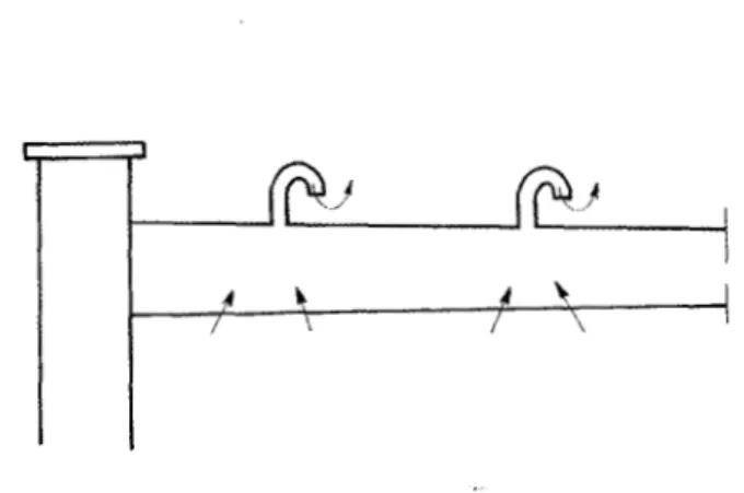
Continuous venting near the centre of flat roofs can be provided by longitudinal vents elevated above the roof level as shown in Figure 18: however, they must be combined with continuous eave vents to be effective. These vents provide more efficient venting than goose necks, which affect only a localized area.
Figure 18.
zyxwvutsrqponmlkjihgfedcbaZYXWVUTSRQPONMLKJIHGFEDCBA
Longitudinal vent above a flat roofVENTILATION OF MANSARD ROOFS
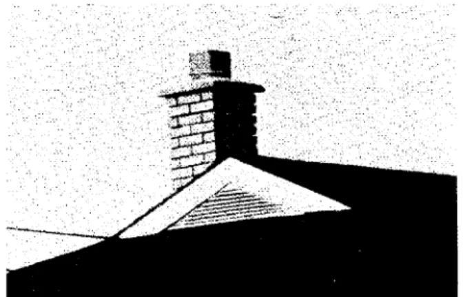
In mansard-style roofs, the lower portion of the roof is steeply sloped, while the upper portion is less-sloped or flat. Many of these roofs have, in the past, experienced problems that can be attributed to poor ventilation or poor airtightness (Figure 19). Ventilation openings located in the soffit of the lower por- tion did not always ensure efficient circulation of air. The ventilating air had to travel too far, and its flow was often restricted by wood framing and insulation. Furthermore, because wind action was not always strong enough to overcome the upward air movement due t o the thermal effect in the steep part of the roof, the moist air became trapped in the upper part. This often resulted in the formation of con- densation and hoarfrost during cold weather
and subsequent inefficient drying.
zyxwvutsrqponmlkjihgfedcbaZYXWVUTSRQPONMLKJIHGFEDCBA
S T A C K W I N D A C T I O N A C T I O N U P W A R D A I R M O V E M E N T D U E TO S T A C K A C T I O N T E N D S T O C O U N T E R A C T T H E W I N D A C T I O N
Figure 19. Inefficient ventilation of a mansard roof
Present practice requires that the upper part of this type of roof be ventilated at the junction between the two slopes as well as at the ridge (if the upper portion is pitched).
A t least half of the required vents should be located near the junction of the upper and lower parts of the roof, and the balance installed near the ridge. Ventilation of the lower part of the roof is no longer considered necessary (Figure 20).
RETROFITTING AND VENTILATION
When insulation is added to the attic of an existing house, the question of whether addi- tional roof vents are necessary is often raised.
1
zyxwvutsrqponmlkjihgfedcbaZYXWVUTSRQPONMLKJIHGFEDCBA
- A T L E A S T H A L FzyxwvutsrqponmlkjihgfedcbaZYXWVUTSRQPONMLKJIHGFEDCBA
OF T H E V E N T S ARE L O C A T E D N E A R THE J U N C T I O NOF T H E L O W E R A N D T H E UPPER ROOFS
2 - O P T I O N A L V E N T S
zyxwvutsrqponmlkjihgfedcbaZYXWVUTSRQPONMLKJIHGFEDCBA
Figure
zyxwvutsrqponmlkjihgfedcbaZYXWVUTSRQPONMLKJIHGFEDCBA
20. Effective ventilation of mansard roofsThe decision to retrofit provides a good opportunity to inspect the attic for signs of mois- ture problems due to condensation. (The inspection can also determine if the existing insulation extends over the top of the exterior walls. If not, it would be worthwhile to cover this area with insulation to reduce heat loss. Care should be taken, however, not to hamper the free circulation of fresh air (Figure 1)).
If an inspection of the attic turns up no sign of moisture problems, it may be wise to leave the roof ventilating system unchanged (provided that there are vents) and t o observe the performance of the attic during the following winter. If, on the other hand, signs of excessive moisture are detected, it would be preferable to correct the problem by improving the airtightness of the ceiling, rather than by increasing the total vent area, a step that risks creating negative pressure in the attic and increasing air leakage through the ceiling. Adding insulation to ventilated flat roofs and cathedral ceilings can present some difficul- ties, especially when done from the inside, since it is difficult to make the ceiling airtight over the entire house. Furthermore, adding insulation from the inside can pose aesthetic problems since it affects the interior finish.
Retrofitting these types of roofs from the out.side may prove a better solution, particularly
if the exist,ing roofing needs replacing. If enough insulation is added above the roof, the roof space no longer needs to be ventilated. The vent, openings can then be sealed since the underside of the roof deck is kept above the dew point temperature of the ambienl air.
CONCLUSION
To reduce the risk of problems resulting from condensation or hoarfrost in the roof space, it is recommended that the relative humidity inside the building be kept a t a low level, and that the ceiling be made as airtight as possible. The total net vent area should be at least equal to 1/300th or 1/150th of the insulated ceiling area (depending on the type of roof space), and be distributed between the upper and lower parts of the roof. Air circulation should be unrestricted by insulation material or the roof framing.
Attic ventilation in the Canadian North presents a more difficult, design problem. The intense cold, the short drying season, the fine snow and the high winds have proven con- ventional venting techniques unsatisfactory. Designing for these conditions may require more e1aborat)e solutions and should be undertaken only by those experienced in cold
climate design.
zyxwvutsrqponmlkjihgfedcbaZYXWVUTSRQPONMLKJIHGFEDCBA
REFERENCES
1. Latta, J . K . Vapour Barriers: What Are They? Are They Effective? Division
of Building Research, National Research Council Canada, Canadian Building Di-
gest
zyxwvutsrqponmlkjihgfedcbaZYXWVUTSRQPONMLKJIHGFEDCBA
No. 175, March 1976.2. Baker, M.C.
zyxwvutsrqponmlkjihgfedcbaZYXWVUTSRQPONMLKJIHGFEDCBA
Roofs. Multiscience Publications Limited, Montreal, 1980.3. Shaw, C.Y. and Brown, W.C. Effect of a Gas Furnace Chimney on the Air Leak- age Characteristic of a Two-Storey Detached House. Division of Building Research,
National Research Council Canada, Building Research Note No. 192, July 1982.
4. National Building
zyxwvutsrqponmlkjihgfedcbaZYXWVUTSRQPONMLKJIHGFEDCBA
CodezyxwvutsrqponmlkjihgfedcbaZYXWVUTSRQPONMLKJIHGFEDCBA
of CanadazyxwvutsrqponmlkjihgfedcbaZYXWVUTSRQPONMLKJIHGFEDCBA
1985, Division of Building Research, NationalResearch Council Canada, Ottawa.
5. CSA Standard CAN3-A93-M82, Natural Airflow Ventilators for Buildings. Canadian Standards Association, 178 Rexdale Blvd., Rexdale, Ontario, M9W lR3.
SUPPLEMENTARY READING
zyxwvutsrqponmlkjihgfedcbaZYXWVUTSRQPONMLKJIHGFEDCBA
Handegord, G.O. Moisture Considerat,ions in Roof Design. Division of Building Re-
search, National Research Council Canada. Canadian Building Digest No. 73, January 1966.
Baker, M.C. Ice on Roofs. Division of Building Research, National Research Council Canada, Cana.dian Building Digest Ivo. 89, May 1967.
Hutcheon, N.B. Humidity in Canadian Buildings. Division of Building Research, National Research Council Canada, Canadian Building Digest No. 1, January 1960. Dalgliesh, A . W . and Schriever, W .R. Wind Pressures on Buildings. Division of Building
Research, Kational Research Council Ca.nada, Canadian Building Digest No. 34,
May 1968.
Wilson, A.G. Air Leakage in Buildings. Division of Building Research, National Research Council Canada, Canadian Building Digest No. 23, November 1961.
Hukheon, N.B. Humidified Buildings. Division of Building Research, National Research
Council Canada, Canadian Building Digest
zyxwvutsrqponmlkjihgfedcbaZYXWVUTSRQPONMLKJIHGFEDCBA
KO.
42, J u n e 1963.Handegord, G.O. Air Leakage, Ventilation and Moisture Control in Buildings. Division
of Building Research, National Research Council Canada, NRCC 20752, 1982.
Baker, M.C. Moisture Problems in Built-up R.oofs. Division of Building Research, Na-
tional Research Council Canada, NRCC 13283, April 1973.
Turenne, R.G. Construction Details for Air Tightness. Division of Building Research, National Research Council Canada, NRCC 18291, April 1980, pp. 25-29.
Handegord, G.O. Vapour Barriers in Home Construction. Division of Building Research,
National Research Council Canada, Canadian Building Digest No. 9, Septem-
ber 1960.
American Society of Heating, Refrigeration, and Air-conditioning Engineers,
zyxwvutsrqponmlkjihgfedcbaZYXWVUTSRQPONMLKJIHGFEDCBA
A S H R A EzyxwvutsrqponmlkjihgfedcbaZYXWVUTSRQPONMLKJIHGFEDCBA
Handbook of Fundamentals. Atlanta, Georgia, 1981, Chaps. 21 and 22.
Storms,
M.
Ventilation des toitureszyxwvutsrqponmlkjihgfedcbaZYXWVUTSRQPONMLKJIHGFEDCBA
B double paroi (Ventilation of Double Wall Roofs).Centre scientifique et technique de la construction, CSTC, Bruxelles, Belgique, revue no 2, juin 1977.
Hansen, A.T. Moisture Problems in Houses. Division of Building Research. National