Publisher’s version / Version de l'éditeur: Building Practice Note, 1985-07-01
READ THESE TERMS AND CONDITIONS CAREFULLY BEFORE USING THIS WEBSITE.
https://nrc-publications.canada.ca/eng/copyright
Vous avez des questions? Nous pouvons vous aider. Pour communiquer directement avec un auteur, consultez la première page de la revue dans laquelle son article a été publié afin de trouver ses coordonnées. Si vous n’arrivez pas à les repérer, communiquez avec nous à [email protected].
Questions? Contact the NRC Publications Archive team at
[email protected]. If you wish to email the authors directly, please see the first page of the publication for their contact information.
NRC Publications Archive
Archives des publications du CNRC
For the publisher’s version, please access the DOI link below./ Pour consulter la version de l’éditeur, utilisez le lien DOI ci-dessous.
https://doi.org/10.4224/20338315
Access and use of this website and the material on it are subject to the Terms and Conditions set forth at The difference between a vapour barrier and an air barrier
Quirouette, R. L.
https://publications-cnrc.canada.ca/fra/droits
L’accès à ce site Web et l’utilisation de son contenu sont assujettis aux conditions présentées dans le site LISEZ CES CONDITIONS ATTENTIVEMENT AVANT D’UTILISER CE SITE WEB.
NRC Publications Record / Notice d'Archives des publications de CNRC:
https://nrc-publications.canada.ca/eng/view/object/?id=db9bccc2-eff6-4249-8a3f-0d2224dc30db https://publications-cnrc.canada.ca/fra/voir/objet/?id=db9bccc2-eff6-4249-8a3f-0d2224dc30db
National Research Conseil national
I
$
Council Canada de recherches CanadaDivision of Building Research
Building Practice
The
Difference Between a Vapour Barrier
and
an
Air Barrier
THE
DIFFERENCE BETWEEN A VAPOURBARRIER AND
A N
AIR BARRIERby R.L. Quirouette
Building Performance Section
Division of Building Research
BPN
54July 1985
IS$N 0701-5216
ABSTRACT
Moisture problems in walls have been attributed in large measure to two mmhanism:
vapour diffusion,
and
now more importantly, air leakage, specifically the deposit ion. of mois-ture by moist air exfiltrating through the building envelope. While significant technology
d a t e d to vapour diffusion control (the vapour barrier) exists (i.e. calculation procedures, regulatory requirements, material standards and performance t esthg ~rocedures), there is minimal technology available related t o air leakage control (the air barrier) for the repair
of existing building envelopes and virtually none for the design and castruction of the
envelope of new buildings.
This paper presents a definition of the air barrier, outlimes the performance requirements,
and examines the application of the theory .to several typical commercial constructions.
This application could provide a functional and durable air barrier within the building envelope.
Les probl6mes d'humidite' dans
les
murs ont k t 6 attribub en grande partie 5 d e np&om&es : la diffusion de la vapear e t celui, plus important, des fuites d'air In*
t m e n t par dCpBt de l'hurnidit& contenue dans 17air qui s3&happe de l'enveloppe d'un
bgtiment).
'Bien
qu'il existe des techniques pour cuntr6ler la diffusionde
la vapeur d'eau(parevapeur
,
mhthodesde
calcul, exigences imposkes par les r&glements, nomes applica-bles aux maeiaux, methodes d'essai)
,
il n'existe que trk peu de moyens pour remedier aux hit- d'air (ktanch6itC 6 l'airj des enveloppa des bgtiments existants et k peu p* rien pour la conception e t la construction de laenveIoppe des bgtiments neufs.Cette communication p&nte une %finition du pare-vent, dkrit I e s exigences relatives b sa performance .et examine l'application de la th6orie
i
divers types de constructionscommercides. Cette application pourrai t pernettre d'obtenir un pare-vent fonc tiomel et
INTRODUCTION
A continuing examination of the performance of buildings in Canada has convinced the
author that air leakage is the leadiig cause of exterior
wall
problem,It
has been linked toefflorescence, spalling masonry; ice build-up under the soffits, frozen pipes and condensation
in cavities, as
well
as rain penetration, high energy costs, and poor control over the indoor humidity conditions. Many of these problems originate earlyin
the building process-
during the working drawing and specification phases-
and not with the materials usedor the methods of construction, as was initially expected. The. principal cause appears to
be a major confusion concerning the fuact ion of the air and vapour barriers,
It is common architectural practice to specify a vapour barrier. Sometimes an airlvapour barrier will be specified, and on rare occasions the term "air barrier" may be used.
This
shows a lack of consistency
in
the use of these terms but, more important,shown
a con- fusionin
the industry about the design, materialsand
methodsd
construction of thew hndamental components of the building envelope. However, the basic confusion is with the functions of these different barriers.A 4
mil
polyethehe sheet will make a g o d quality vapour barrier and twelveinches
ofcast-in-place concrete will make a good quality air barrier. This would
be
too restrictivea definition, bat the Eunctions of these two barriers are as different as polyethylene and concrete.
In
practice many mateEiaIs can be used as effective vapour barriers and many may beeffective air barriers. The choice of materials or combination thereof and the method of
assembly, are dependent on the function. A clear understmding of the functions of the
two
types of barriers is imperative to good design, and to effective and predictable buildingenvelope performance.
VAPOUR
DIFFUSION CONTROL(THE
VAPOUR BARRIER)The principal functipn of' a vapour bamier is to stop or, mare accurately, to retard the
passage of moisture as it diffuses through the assembly of materials in a wall.
Diffusion is
the
process by which water vapour migrates through a materia1 (Figure la).The
rate at which water vapour migrates - or diffuses
- depends on two factors: the difference between
the water vapour pressure in the air inside the building and that in the outside air, and the E
sistmce that materials present to the migration of moisture by diffusion.
E~DW
Emmcllen
[%)
WALL IITliDuT A rA?WI1 BllRRIUl
FIG 1A
The
moisture diffusion control pmperty of a material is called its %a& vapour perme aace". This is usually expressed as the weight of moisture that will diffuse through a givenarea and thicknms of materid, over a specified period of time
at
a unit vapour pressure dif-ference.
For
-le, a sheet material, 0.1mm
thick, having a water vapour permeance of10 will allow 10 nanograms of moisture to pass
through
one square metre of the material persecond when the difference in water vapour pressure is one pascal. In practice, a h u m
allowable rate of 15 is the accepted water vapour permeance standard (CAN 2-51.3~M80)
for a Type
I
vapour barrier. Any material having a rating of 15 or less, may be suitable asa Type
I
vapour barrier, provided that it meets the other conditionsd
the standard.All materials have a resistance to moisture dif-
fusion, some more than others. Water vapour
migrates through air, polyethylene film, fibre board, concrete and many other materials, bat at varying rates. A vapour barrier is a material that offers a higher resistance to the diffusion of water vapour than most other materials. It
is
usually placed on the warm side of the insula- tion (Figure 1
b)
.
Polyethylenefilm
of sufficient thickness is the material most commonly usedfor this purpose; however, other materials such
For example, assume tbat the
wall
section inFigure 2 is a single stud space exposing to the
room side one square metre of the vapour bar-
rier.
The
barrier has a water vapour pexmeanceof 5 ng/Pa.s-m2 (0.087 graimlh-ft2-in
Hg),
the
room conditions are 21' C, 30% relative
humidity,
while
the
sheathing is at -20°C.If
these mndi-tions prevaiIed for one month, approximately six
grams of moisture wodd diffuse into the cavity,
Thii w d d create only a
thin
layer of fro&on
the inside surface of the sheathing.-
-- -[E)
El
(2%)
mmr W L WITH A vllppl~t ~lllgfu~ FIG. 18 . _ lllnDEIE'KL
m-
[a%]
BlllllffElYlPOlllwnRImrnEvEn8 VAPOllll D f r n I O l Bur MOI M U tMtlCLGE FIG. 2
as aluminum foil, some paint products, some
in-
sulation adhesives (mastics), metal, glass, and even concrete of s&cimt thickness may be quite suitable as mpour barriers.
This
dues nut mean that diffusion control is unimportant and that the vapour bmier canbe
omitted. A vapour barrier is important, particularly in high humidity buildings suchas computer centers, museums, hospitals,
add
public swimtning pools.For
the vapwr barrier to control condensation resulting from vapourdiffusion
it mustbe
placed on or near the warm side of the insulation, which is n o r d y the high vapow pmsure side. Contrmy to popular belief, a vapow barrier need not be perfectly c w t i n - urn. Unsealed lapsand
pinholes,
minor cuts, etc., do not increase the overdl moisturediffusiori rate into a wall or roof cavity appreciably. It
ia
worthwhile, however, to avoidthese imperfections 'if ppossible.
AIR LEAKAGE CONTROL (THE AIR BARRIER)
Water vapour diffusion is only one of
the
mechanisms by which water c a n be transported into a wall or roof cavity. The provision of a vapour barrier within the wall or roof assemblysatisfies only part of the requi~ement of controlling moisture entry into
building
enclosures,The other mechanism,
which
is now considered to be far more significant, is air leakage. Air leakage occurs when openings (holes, cracks, etc.) in the building envelope form a continuous path from 'wide to outside and an air pressure difference occurs across it.Both mechanisms may, of course, operate at the same time.
The principaI function of the air barrier is to stop outside air from entering the building
through the walls, windows w roof, and inside air from exliltrating through the building
envelope to the outside. This applies whether the air is humid or dry, since air leakage can result in problems other than the deposition of moisture in cavities. Exfiltrating air carries away heating and cooling energy, while incoming air may bring in poIIution as well as disable a rain screen wall system.
Moisture-laden air passing through an
insdated
cavity with a vapour barrier may depositmuch more moisture than
would
diffuse through the vapour barrier in the same period oft h e .
For example, if the room side surface
in
Figure 2 were opened t o the cavity, perhapsthrough an electrical outlet or a senrice pipe penetrating to
the
inside, with a net openingarea of 625 mm2 (1 in2), 2600 m3 (91818 ft3) of air would enter and exit the cavity to the outside under a 10
Pa
(0.2 lbs/ft l ) pressure difference (equivalent to a 15km/h
(9.3 mph)wind) over one month. This would amount to approximately 3000 kg (6614 ibs) of air and 14 kg (30.9
Ibs)
of water. Assuming further that only10%
ofthis
water condenses outin
the
cavity,then
air leakage has deposited 233 times (10% of 14 kg, 14M) g/6 g) the amountof moisture that passed by diffusion cmly.
Air Leakage Paths
Holes
or openings through the envelope can take maay forms, for exmnple: cracks orjoints between infill components and structurd elements, or poor connections between
the wall
and
the roof and at openings for building services. They may occur even inporous materials, for example concrete
block,
h i
density g l w fibre, open cell polystyrene insulation, and fibreboard. Some openings follow direct chmnels from inside to outside,as in an uncapped steel deck at the perimeter of a floor or ceiling. Others may appear on an inside surfxe
W s h
(behind a radiator cabinet or above a suspended ceiling), leadinginto a waU cavity arnd an through holes at some other location in
the
outside finish, or asweep or vent holes in brickwork. Same openings may develop after construction because
and contraction of building elements, ar deflection orbeams. Other openings may result from an inappropriate choice of joint materials.
Air Pressure Difference
Air leakage through the openings
in
the build-,
ing envelope is caused by air pressure differences
fmm
one or more of three sources (Figure 3).The first is the stack effect or the chimney effect, dependent on a temperature difference between
the
b i d e
and the outside of a building. Secund,a pressure difference may also be induced acr-
the
building envelope by wind f c e s acting on it.Third,
the operation of ventilation equipment may produce a pressure difference. The net airpressure difference across a wall or roof may be
a combination of all three, and it is not the same
at a11 parts of the building envelope. The size
of this difference can also vary considerably -
fmm one to ten pascals ( 0 1 1bs/ft2) in a small h o w , and periodically as
high
as 2000 pascals(42
lbs/ft2)
under the highest wind load, stack effect and fan press&siion conditions.Stack
effect.The
stack effect resultsfrom
warmerinside
air having a lower densitythan the
cooler outside air. This differencein
density creates a slight outivard positive pressure atthe
top of a building, whiie exerting a s l i t inward negative pressure at thebase. Hence, air will tend to injiltrate at the lower levels of the building and exfiltrate at
the uppa levels. Typically, this represents a 50
Pa
(1 1b/R2) inside/outside air pressuredifference at the roof line of a 25 storey building in mid-winter, assuming that the neutral pressure plane is near the middle of the building. Simultaneously, there wil1 be a 50
Pa
pre6Sure difference at the lobby level which is acting inwardly. (This air pressure difference
is often the mason why outward swinging doors are difficult t o open at the
lobby
level of high rise buildings, and we reason for the useof
revolving doors.)Wind.
Wind causes i d b a t i o n on the windward side of a building and dItration onthe
leeward side and onthe
sides parallel to the wind direction. Similarly a flat roofwill
generally have d t r a t i o n because of negative pressure caused by wind. Since windvelocity increases
with height,
the diierence in pressure w m s the building envelopealso
i n c r e w
with
height.Pressure distribution on the windward fa@e vari.es
from
a maximum in the centre, di-minishing towards the perimeter. Suction pressures, on the other hand, may vary from a maximum at t h e perimeter, diminishing towards the centre, The pressure on the side walls parallel to the wind is normally negative, but rnay change rapidly in value and wen
If a window is opened on the windward side of a house, the interior pressure will rise and
become almost equal to the pressure on the exterior wall facing the wind. The other walls
and the roof, however, may undergo a substantial increase in air pressure difference, which
in turn may substantially increase the d l t r a t i o n through the ceiling and the leeward walI of the building.
Fan
preseurieation. Ventilation air for a building is provided byfans.
They may be as small as a bathroom fan for a dwelling or as large as a house for some types of eomercial, industrial or hstitut ional buildings,Regardless of size,
they
are usually called upon to introduce or to exhaust airf m
abuilding.
They
maybe
set positively (supply greater than exhaust) to pressuri~e the building;this
is done in highriie structlues to minimizethe
air pressure difference at lobby levels caused by stack d e c t . They maybe
set negatively (exhaust greater than supply) toprevent any moist air from entering
the
roof or wall cavities by d t r a t i o n ;this
could bedone for an indoor swimming pool enclosure.
Ventilation by fans may prodnce a s m d but significant air pressure difference m a s s the building envelope.
This
force should be recognised during the design of the buildingenvelope, as some materials may be forced out at joints or come apart at seams under sustained pressures.
Structural Considerations of Wind Forces
Occasional high winds may produce high
p-ure differences across a waII
a d
putstress not only on the cladding
but
on thosematerials in the wdi or roof cavity which
have an inherent
high
resistance to air leakage[for cxmpIe, concrete decks, roofing mem-
branes, precast panels) or on those materi-
als
(the air/vapour barrier) that are desig-nated to control air leakage.
If
the
air pres- sure d'xfference exceeds the capability of the air barrier systemin
support theload, then
air tightness will be destroyed
and
a perma-nently increased air leakage wiIl result (Fig- ure 4). It is ismost important to re- that if
an air pressure difference cannot move air, it
will
act to displace the materids that preventthe air from flowing.
YIm eBEB8qAe -0 WLPrmYtElE FIU W OlXK
h
a relativelynew
shopping center same ofthe insulation, attached by spot adhesive to a
block wall, separated from the backup bbck
and fell onto the soffit ceiling platform of the large overhanging roof (Figure 5). When wind action (a large door opened on the wind- ward side) caused the building interior pres-
sure to rise, the air pressure acting through
the
porous block wall apparently pushed theinsulation with suEcient force to overcome
the
strength ofthe
adhesive, resulting in theseparation. This case illustrates the impor-
tance of pressure differences acting across t h e
most air
impermeable
material, which may not be attached securely to the supporting structure and was not intended to stop air.Each membrane or assembly of materials intended to support a differentid air presgure
load must
be
designed and construhd to carrythat
l a d ,
or it must receivethe
neces-sary support from other elements of
the
wall, If the air barrier system is made of flexiblematerials then it must be supported on both sides by materials capable of resisting the peak
air
pressure loads; or it mustbe
made of self+upporting materials, such aa board products adequately fastened to the structure. Some membrane products may be satis- factorilyadhered
to asolid
substrate t o form a composite air barrier system [membraneplus substrate), for m p l e , a rubberized asphalt membrane applied ta the surface of a
masonry hi21 wall.
AIR
B A m R DESIGN REQUIREMXNTSMaterials and the method of assembly chosen to build an air barrier must meet sweral
requirements
if
they are to perform the air leakage control function successfully.1. There must be continuity throughout the building envelope.
The
air barrim materialof the wall must be continuous with the air barrier material of the roof (e-g., the
roohg membraae).
The
air barrier material of the wall must be connected to the2. The air barrier system must be fastened to a supporting structure to resist a peak
wind load, a sustained stack effect or pressurization from ventilation equipment; it must be sufficiently rigid to resist displacement.
a) The materids and canfiguration of the air barrier assembly must resist the highest expected air pressure load, bward or outward, without rupturing or detaching from the support.
b)
The
assembly must not creep away from a substrate or paxt at a joint under asustained air pressure diflerence (such as stack effect or fan pressurization).
GI
The deflection of the air barrier mateiials between supports must be minimized ta prevent the displacement of other materials (such as insulation in cavities). 3. The air barrier system must be virtually air-impermkahle. A d u e for the maximumallowable air permeability
has
not yet been determined. However, materialssuch
as polyethylene, many single ply ma&g membranes, gypsum board, cast-in-place concrete, metal or glass qualify as low air impermeable materials, whereas concreteblack, acoustic insulation, open cell polystyrene insulation or fibreboard would not.
The
metd and glass curtainwail
industry, notablyin the U.S., has
adopted a value of 0.3 L/rn2-s (0.06 CFM/ft2) at 75 Pa (1.57 lbs/ft2) as the maximum allowable airleakage rate for these t y p ~ of
wall
construction. This value however is consideredhigh for buildings in Canada and some C d i a n manufactnrers of metal and glass
curtain wall systems claim that their system will meet 0.1
Lid-s
or better for thesame air pressure difference, However, even this may still be too high.
It
is not d i c u l t to find material which has aleakage
of practically zero. But, it is the totalassembled air barrier system (main areas plus joints) which must
exhibit
practicallyzero leakage.
4.
The
air barrier assembly must be durable inthe
s a m e sense that the building isdurable, and be made of materials that are k n m to have a long service life or be
positioned so that it may
be
servicedfrom
time to time.AIR BARRIER DESIGN APPLICATIONS
Combined Air and Vapour Barriers
A wall or roof assembly will require an air barrier and poesibly also a vaponr barrier.
They m y or may not
be
the same material. But a wmbiied system must meet the designh
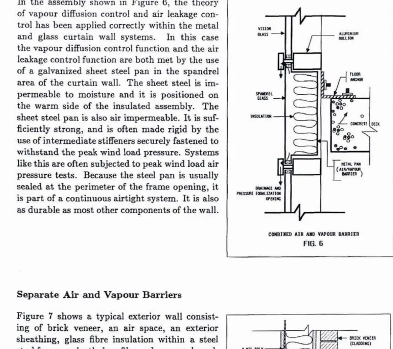
the assembly shown in Figure 6, the theoryof vapour diffusion control and air leakage con-
trol has been applied correctly withim the metal
and glass curtain wall systems. In this case
the vapour diffusion control function and the air leakage contml function are both met by the use of a gaivanized sheet steel pan in the spandrel area of the curtain wall. The sheet stel is
im-
permeableto
moisture and it is positioned onthe warm side of the insulated assembly. The sheet steeI pan is also air irngerxieable. It is suf-
ficiently strong, and i s &en
made
rigid bythe
use of intermediate stiffeners securely fastened to withstand the peak wind load pressure. Systems Iiie
this
are offen subjected t o peak wind loadw
pressure tests. Because the steel pan is usually sealed at
the
perimeter of the frame opening, it is part of a continuous airtight system. It is alsoas durable
ars
mat
other components of thewall.
Wm11BB AIB 1111 Y M W R W I E I I
FIG. 6
Separate Aim
and
Vapour BarriersFigure 7 shows a. typicaI exterior
wall
consist- 1I
ing of brick veneer, an air space, an exterior
sheathing, glass fibre insulation within a steel
stud frame, polyethylene film and gypsum board.
h
this case the polyethylene is intended as thevapour diEnsion control element. It meets the
requirement of water yibpour d i h i o n resistance
for a Type
I
vapour barrier and is pwitioned onthe warm side of the assembly. However,. the
design and the appearance of
the wall
departfrom normal practice.
The
inside gypsum board is designated as the air barrier, rather than the,
,
,
(Frn=
SEMW~E m f s m V A P ~ IMURIERS
FIG 7
polyethylene. The polyethylene would probably
meet the air barrier requirements
if
it were adequately supported on both sides. In m a te m , however, it is the low density glass fibre .insulation which is used to support it on the
cavity side. This support m a y not be sufficient for pressures due to high winds- Another difficulty is that there is no adhesive known that will form a lap joint with the same strength
as the polyethylene. The layer of gypsum board sheathing can meet all the requirements of
airtightness if all joints are taped and a continuous air seal with other components of the
envelope is provided. Although the gypsum board may not be as durable as sheet steel, it
is accessible and therefore serviceable.
Position of the Air Barrier
A vapour barrier is usually placed on
the
warm side of the insulation. It may also be positioned part way into the insulation but, for satisfactory performance, it shouldbe
nofurther in than the point at which the temperature of the inside air drops to its dew point.
While it is preferable that the air barrier system be placed on the warm side of an insulated
assembly, it is not an essential requirement as it is with the vapour barrier. The position of the air barrier in a wall or roof is more a matter of suitable construction practice
and
the type of materials to be used. However, if this barrier is positioned on the outside of the
insulation, consideration must be given to its water vapour permeability
in
case it shouldalso act as a barrier to vapour which is on its way out from inside the wall assembly. This
situation may be prevented by choosing an air barrier material that is ten to twenty times
more permeable to water vapour dsusion than the vapour barrier material.
There
are many situations in practice in which theair barrier of a wall or r m f is on the outside of the
insulation and performs quite satisfactorily.
In
the
case of a typical medium rise apartment building, whichhas
a decorative exposed cast-in-place con- crete shear wall (Figure 8 ) , the exterior facade isinsulated on the inside. Further, it usually has a 0.1 mm (4 mil) poIyethylene vapour barrier and a
gypsum board interior finish. In practice, the cast- in-place concrete exterior walI is a continuous and
structurally adequate air impermeable element of the wall and therefore acts as the air barrier. The
vapour barrier is the polyethylene, and so long as it, the imulation and the interior surface ofthe concrete
shear wall are in intimate contact, the waIl will per-
form quite satisfactorily, as it has in many existing buildings.
If
the insulation is not in intimate contact with the concrete, convection within the cavity mayseriously alter the thermal performance of the insulation. A prerequisite of m y w
dl
designis that the insulation be in intimate eontact with the air barrier. But the general opinion
among most researchers and practitioners is that the air b h e r should be placed the
warm side of the insulation, where thermal stresses will be at a minimum. (Inside of the
Joint Desigm
While the discussion above has been concerned with the flat areas of walk or ceilings, the joints between them may well present the most important design and constructbn
problems. There are many kinds of joints but for the purpose of this discussion the
following are considered the most critical: the rocrf/wall connection, the wall/foundation
connection, the walI/window or /door connection, soffit connections, corner details, and
connections between different types of exterior
wall
system, such as brickand
precast, curtain wall and brick or precast,steel
s i d i i and curtain wall.To
illustrate one joint design problem, Figure 9ashows a wall/roof connection typical of many
smaII commercial buildings. A steel joist rests on a load bearing block- The roof is composed of
a conventional
B.U,R.
membrane over an 'mula-tion layer, which is over a vapour barrier fastened to a steel deek- The wall consists of a decora-
tive exterior
100
mm (4 in) concrete block, and a 25 nun(1
in) cavity (air space),with
a spotadheared insulation. As
the
air flow armm in- dicate, this type of wall is subject to a serious air exfiltration problem through the block sur-face
and joints, often resulting in spalled exteriorblock, icicles forming on the exterior surface, and rain penetration problems.
No
matter how well this wail section is built, its performancewill
notimprove. It is the design
that
requires correctivemeasures-
To
correct the situation two design changesshould be
made.The
first is depicted in Fig-ure
Qb.
Since the wall is as permeable to air as a fly screen (through the joints between theblocks), an air impermeable plane must
be
built ontothe block
surface b.dore the insula- tion is installed. The air barrier (an air impermeable material combined with a block wall), may be cement paging (questionable long term or perhaps a board product fastened mechanically tothe
block wall with all
joints sealed, or a reinfarced rubberizedmembrane. Regardless of the materials chosen, the air barrier must be impermeable to ajr
,
AIR LEAKS AT ROOF= -ION
FIG. 98
The
insulation couldbe
attached to the air barrier (which could also senre as a vapour barrier) followed by an air space and theblock
veneer. This design change brings a positive solution to the airtightness function of the wall.The second design change involves the connection between the w d and
the
roof-In
Figure 9c
the
200 mm (8 in) parapet blockhas
been replacedwith
a 100 mm (4 in) bIock, andthe
roof membrane (the air barrier) is fastened to wood blocking that is boltedto
the steel deck. An air barrier material [preferably sheet steel or heavy r o o k membrane) is then connected
from
the roof membrane tothe
air barrier material ofthe
wall.
The
air barrier of
the
roof is now appropriately connected tothe
air barrier of the wall.The
remainder of the components, that is,
the
huIation, the masonry, the cap and counter flashings are installed afterwardswith
the masom and the insulation of the wall.This joint design problem illustrates how airtightness control, vapour diffusion control,
and thermal resistance continuity m a y be achieved at the m f / d junction for this type of building, without altering
the
architecturd lines of the roof or the appearance of thef q d e -
It
does not add s'lgnificmt cost to the construction process. Joint design must, ofcourse, take
info
account the sequence of construction and the jurisdiction of the variousCONCLUSIONS
The function of the vapour barrier is to retard water vapour diffusiun into insulated build-
ing envelope assemblies. Vapour diffusion control is simple t o achieve and is primarily a
function of the water vapour diffusion resistance of the chosen materials and their position
within the building envelope assembly. The barrier should be clearly identified by the designer and clearly identikble by the builder.
Air ieakage control is a more complex objective, which must be considered as a separate and distinct function for any wall, roof, window and especially joint detail, and even for
the below grade portion of the building envelope. The function of the air barrier is to
dimiiate the through flow of air from inside to outside and vice vma. An air barrier must
be continuous, be structurally fastened or supported to withstand a peak air pressure
load, and be virtually impermeable to the passage of air. It must be durable or easily
serviced. Again, it is important that the designer clearly identify the air barrier and that the builder recognize it as such.
It
is desirable, but not essential, that itbe
installed
onthe warm side of the insulation, so that thermal stability will be improved and access
for future maintenance be assisted. The vapour and air barriers may or may not be the
same material; if they are the same material, then it must meet all the requirements of
airtightness control and
of
vapour d i h i o n control.If
the barriers are notthe
same material, then the vapour barrier material need onlymeet the requirements for vapour diffusion control and the materials designated for