HAL Id: hal-01682484
https://hal.archives-ouvertes.fr/hal-01682484
Submitted on 12 Jan 2018
HAL is a multi-disciplinary open access
archive for the deposit and dissemination of
sci-entific research documents, whether they are
pub-lished or not. The documents may come from
teaching and research institutions in France or
abroad, or from public or private research centers.
L’archive ouverte pluridisciplinaire HAL, est
destinée au dépôt et à la diffusion de documents
scientifiques de niveau recherche, publiés ou non,
émanant des établissements d’enseignement et de
recherche français ou étrangers, des laboratoires
publics ou privés.
Mesoporous binder-free monoliths of few-walled carbon
nanotubes by spark plasma sintering
Christophe Laurent, Ty Mai Dinh, Marie-Claire Barthélémy, Geoffroy
Chevallier, Alicia Weibel
To cite this version:
Christophe Laurent, Ty Mai Dinh, Marie-Claire Barthélémy, Geoffroy Chevallier, Alicia Weibel.
Meso-porous binder-free monoliths of few-walled carbon nanotubes by spark plasma sintering. Journal of
Materials Science, Springer Verlag, 2018, vol. 53 (n° 5), pp. 3225-3238. �10.1007/s10853-017-1784-0�.
�hal-01682484�
Open Archive TOULOUSE Archive Ouverte (OATAO)
OATAO is an open access repository that collects the work of Toulouse researchers and
makes it freely available over the web where possible.
This is an author-deposited version published in :
http://oatao.univ-toulouse.fr/
Eprints ID : 19430
To link to this article : DOI:10.1007/s10853-017-1784-0
URL :
http://dx.doi.org/10.1007/s10853-017-1784-0
To cite this version : Laurent, Christophe
and Dinh, Ty Mai
and
Barthélémy, Marie-Claire
and Chevallier, Geoffroy
and Weibel,
Alicia
Mesoporous binder-free monoliths of few-walled carbon
nanotubes by spark plasma sintering. (2018) Journal of Materials
Science, vol. 53 (n° 5). pp. 3225-3238. ISSN 0022-2461
Any correspondence concerning this service should be sent to the repository
administrator:
staff-oatao@listes-diff.inp-toulouse.fr
Mesoporous
binder-free monoliths of few-walled
carbon
nanotubes by spark plasma sintering
Ch. Laurent1,*, T. M. Dinh1, M.-C. Barthe´le´my1, G. Chevallier1,2, and A. Weibel1
1
Université de Toulouse, CIRIMAT, CNRS-INPT-UPS, Université Paul-Sabatier, 118 Route de Narbonne, 31062 Toulouse Cedex 9,
France 2
Plateforme Nationale CNRS de Frittage Flash, PNF2, MHT, Université Paul-Sabatier, 118 Route de Narbonne,
31062 Toulouse Cedex 9, France
ABSTRACT
Carbon nanotubes with few walls (FWCNTs) are prepared by catalytic chemical vapor deposition. Transmission electron microscopy investigations for each sample show the average number of walls (3, 4 and 8) as well as the internal and external diameter distributions. Binder-free FWCNT monoliths are prepared by spark plasma sintering (SPS) at temperatures in the range 1000–1600 °C. A combination of techniques including Raman spectroscopy, scanning- and transmission electron microscopy, electron microdiffraction is used to charac-terize the samples. Compared to the FWCNT powders, the high temperatures used for SPS favor the elimination of surface defects in CNT walls but also some limited amorphization, without dramatic damage to the CNTs. Increasing the
SPS temperatures produces an increase in densification. N2
adsorption–des-orption cycles revealed that the powders and monoliths show microporosity
and, mostly, mesoporosity. Some monoliths show a specific surface area equal to
about 500 m2/g. The 4WCNTs when consolidated into monoliths by SPS at 1000
or 1100 °C are able to retain a high amount of mesoporosity that contributes to a
high porous volume of the order of 0.8 cm3/g.
Introduction
Carbon nanotube (CNT) monoliths (also denoted as CNT compacts) are attracting much interest because
they may have exceptional physical [1–7] and
mechanical properties [8–13]. They may present some
meso- and macro-porosity [14–16] and are considered
biocompatible [11, 12]. To the best of our knowledge,
all reported works are performed on multi-walled
CNTs (MWCNTs) with outer diameters typically in the range 10–50 nm, corresponding to CNTs with
about 10–50 walls [17], except one report using
sin-gle-wall CNTs (SWCNTs) [10] and one using
double-walled CNTs (DWCNTs) [15]. Few-walled carbon
nanotubes (FWCNTs) have 3–6 walls (some authors
[18] also include the DWCNTs) and show both the
high aspect ratio of SWCNTs and DWCNTs and the robustness of MWCNTs while containing less
structural defects than the latter, making them
interesting for many applications [18–22]. The aim of
the present paper is to prepare binder-free FWCNTs monoliths by spark plasma sintering and to investi-gate the density, presence of defects and porosity. Some monoliths show a specific surface area about
500 m2/g as well as micro- and mesoporosity and
high porous volume.
Materials and methods
Carbon
nanotubes
The FWCNTs were synthesized by a catalytic chem-ical vapor deposition (CCVD) route described
else-where [23, 24]. First, two oxide powders were
prepared, the formulas of which are written as Mg0.99(Co0.33Mo0.67)0.01 and Mg0.90(Co0.33Mo0.67)0.10
for commodity and are denoted powders A and B,
respectively. Indeed, free MoO3 particles are present
because the molybdenum ions do not enter the rock salt lattice of MgO. Powders A and B were submitted
to a CCVD treatment (H2–CH4 with 18 and 36 mol%
CH4, respectively, heating and cooling rates 5 °C
min-1, maximum temperature 1000 °C, no dwell).
This produced CNT-Co–Mo2C–MgO, denoted
pow-ders AR and BR, respectively, which were soaked in a 37% HCl aqueous solution in order to dissolve MgO
as well as unprotected Co and Mo2C particle [25].
Indeed, previous studies [26, 27] have shown that
unlike nitric acid or other oxidizing acids, HCl does not damage the CNTs (no opening of the CNTs, no oxidation of the tips and defects which may be pre-sent on the outer sidewalls). The acidic suspensions were filtered on 0.45 mm pore size cellulose nitrate membranes (Whatman) and washed with deionised water until neutrality and subsequently filtered and washed with ethanol. Finally, the samples were dried overnight at 80 °C in air. The CNT powders derived
from the A and B powders will be denoted 3WCNT
and 4WCNT hereafter, respectively, denoting the average number of walls (N) as discussed later in the text. For the sake of comparison, an MWCNT powder was purchased from Nanocyl (Belgium). It was pre-pared using a CCVD route but the precise experi-mental details are not known to the authors. A
previous study [28] revealed that N is equal to 8 and
therefore the MWCNT sample will be denoted
8WCNT hereafter.
Spark
plasma sintering
The CNT powders were divided into several batches, which were consolidated by spark plasma sintering (SPS, Dr Sinter 2080, SPS Syntex Inc., Japan). They were loaded into a 8-mm inner diameter graphite die. A sheet of graphitic paper was placed between the punch and the powder as well as between the die and the powder for easy removal. The powders were sintered in vacuum (residual cell pressure \ 10 Pa). A pulse pattern of twelve current pulses followed by two periods of zero current was used. A heating rate of 300 °C/min was used from room temperature to 600 °C, where a 1-min dwell was applied. A uniaxial charge was gradually applied during the ramp and dwell, reaching a value corresponding to 100 MPa on the pellet. Then, the temperature was raised (100 °C/ min) to a maximum in the range 1000–1600 °C, as required for the study, where a 3-min dwell was applied. An optical pyrometer, focused on a little hole at the outer surface of the die, was used to control the temperature. Natural cooling was applied down to room temperature, and the uniaxial load was gradually released during the same time. The sintered specimens were in the form of pellets 8 mm in diameter and about 2 mm thick. The sintered specimens will be noted as in the following example: 3W1100, 3W indicating that the 3WCNT powder was used and 1100 denoting a SPS temperature equal to 1100 °C.
Characterization
The composite powders and CNT samples were observed by field-emission gun scanning electron microscopy (FESEM, JEOL JSM 6700F) and trans-mission electron microscopy (TEM, JEOL JSM 2100F operated at 200 kV). The carbon content in the CNT
powders was determined by flash combustion. N2
adsorption–desorption isotherms of the CNT
pow-ders and monoliths were measured at liquid–N2
temperature (Micromeritics ASAP 2020). The samples were previously degassed by heating at 120 °C under a primary vacuum for 12 h. Specific surface areas
(SBET) were calculated using the BET equation. Pore
size distributions were calculated from the desorp-tion branch using the non-local density funcdesorp-tional theory (NLDFT) kernel in the MicroActive 3.00 soft-ware. Selected samples were studied by Raman
spectrometer using the 633 nm laser excitation). The density of the pellets was calculated from their weight and dimensions. A selected monolith was observed by FESEM and TEM. Focused Ion Beam (FIB) FESEM (FEI Helios 600i) was used for the preparation of a cross-sectional foil of the monolith for TEM observations. Prior to cutting with a focused
Ga?ions beam (maximum current 65 nA), a strip of
Pt was deposited above the area of interest in order to protect it from ablation and Ga-implantation during preparation. Energy-dispersive X-ray spectroscopy (EDS, Bruker Silicon drift detector (SDD) with a res-olution of 127 eV) and electron microdiffraction were performed during TEM observations.
Results and discussion
Carbon
nanotube powders
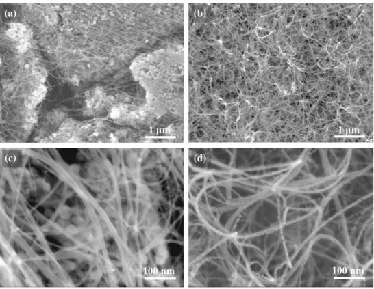
The carbon content in powders AR and BR is equal to 15.00 and 87.10 ± 0.02 wt%, respectively. FESEM
images of powder AR (Fig. 1a, c) reveal the presence
of long, flexible filaments, with a smooth and regular surface, on the surface of the oxide grains and bridging several grains. No thick, short carbon
nanofibers are observed. All filaments have a
diam-eter lower than 30 nm and a length on the order of some tens of micrometers. From the results of
pre-vious studies [23, 24, 29], it is known that such
fila-ments are isolated CNTs and/or CNTs bundles. For
1 µm 100 nm 1 µm 100 nm (a) (b) (c) (d)
Figure 1 FESEM images of the CNT-Co/Mo–MgO composite powders:a, c powder AR and b, d powder BR.
Table 1 Average number of walls (N), average internal diam-eter (dint), average external diameter (dext) and approximate
length (L) of the CNTs, theoretical density of the CNT (q0),
carbon content in the CNT samples (Ce) (the balance is mostly
adsorbed water and residual metal catalyst), Raman ID/IGratio,
specific surface area of the CNT samples (SBET)
Specimen N dint(nm) dext(nm) L (lm) q0(g/cm3) Ce± 0.2 (wt%) ID/IG SBET(m2/g)
3WCNT 2.7 2.1 3.5 [ 5 2.09 90.5 0.08 534
4WCNT 3.6 2.6 4.6 [ 5 2.06 97.3 0.16 493
BR (Fig.1b, d), the CNT bundles are so numerous, in agreement with the high carbon content, that they completely cover the oxide grains. The selective reduction of the starting oxide leads to the formation of nanometric Co particles which immediately
cat-alyze the decomposition of CH4, which is helped by
increasing proportions of MoO3[24,25] and are thus
progressively loaded with carbon atoms (activation of the nanoparticles). The carbon concentration in the nanoparticles then increases until reaching the solu-bility limit, followed by the nucleation and growth of
a single CNT on each activated metal particle [30]. It
is a complex balance between the relative global proportions of amounts of catalyst (Co), activator
(MoO3) and carbon source (CH4) that determine the
local conditions around each activated particle which will in turn determine the number of walls of the
corresponding CNT [24,25,31–33].
The carbon content in the CNT powders (Ce—
Table1) is equal to 90.5 wt% for 3WCNT, 97.3 wt%
for 4WCNT and 91.8 wt% for and the commercial 8WCNT sample. The balance corresponds mostly to
adsorbed water and residual Co and Mo2C particles.
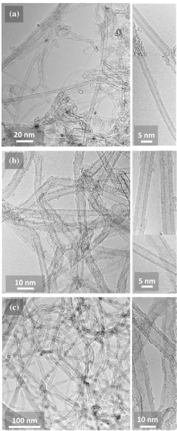
The CNT powders were investigated by TEM.
Typi-cal images are shown in Fig.2. The presence of
structural defects along the CNT walls and non-tubular carbon at their surface may result from degradation under the electron beam, although it is
clear that the 8WCNTs (Fig.2c) contain significantly
more defect such as kinks, uncompleted walls, bam-boo-like structure and variation of the diameter, along the length of the CNTs. They also are not bundled. The number of walls was measured for about 100 CNTs on HRTEM images. The average
number of walls (N) is shown in Table1. For the
3WCNT specimen (Fig.3a), CNTs with 1–7 walls are
observed. The DWCNTs are dominant (40%) with 3WCNTs (29%) the second most abundant CNTs. N is equal to 2.7 which was rounded to 3. For the
4WCNT specimen (Fig.3b), CNTs with 1–7 walls are
also observed but now the 4WCNTs are dominant (30%) with 3WCNTs (28%) the second most abundant CNTs. N is equal to 3.6 which was rounded to 4. For
the 8WCNT sample (Fig.3c), CNTs with 3–22 walls
are observed. The 8WCNTs are dominant (30%) with 7WCNTs and 9WCNTs (both 16%) the second most abundant CNTs. N is equal to 8.5 which was rounded to 8. The internal and external diameter distribution also derived from HRTEM measurements are shown
on the right-side panel of Fig.3. The average internal
and external diameter (dint and dext—Table 1) are in
excellent agreement with the empirical law giving the correlation with N for a population of MWCNTs
(a)
20 nm
5 nm
(b)
10 nm
5 nm
(c)
100 nm
10 nm
Figure 2 TEM images showing typical CNTs present in the a 3WCNT, b 4WCNT and c 8WCNT samples.
prepared by CCVD [17]. The theoretical density of
the CNTs (q0—Table1) was calculated using the
CNT density chart [34]. It was also attempted to
evaluate CNT length (L—Table1) on transmission
electron microscopy images, although it is very dif-ficult for the 3WCNT and 4WCNT samples because the CNTs tend to form bundles as noted above.
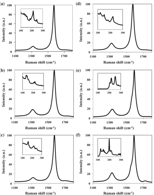
The Raman spectra of the CNT powders are
com-pared in Fig.4. ID/IGrepresents the ratio between the
intensity of the D band (about 1320 cm-1) and the G
band (about 1580 cm-1). An increasing ID/IG value
(8, 16 and 190% for 3WCNT, 4WCNT and 8WCNT, respectively) was reported to reflect defective sites or
sp3-hybridized carbon atoms [13], accounting for
defects in CNT walls and disordered material
surrounding the CNTs [26]. The low-frequency range
of the spectra for 3WCNT (Fig. 4a) and 4WCNT
(Fig.4b) shows radial breathing mode (RBM) peaks,
indicating the presence of small-diameter CNTs, such as SWCNTs and DWCNTs, in agreement with TEM
data (Fig.3). Note that the Raman process is
influ-enced by optical resonance, and it is thus impossible to detect all present CNTs using only one wave-length. Moreover, the peak intensities do not reflect the real amount of individual CNT because the res-onance effect amplifies the Raman signal from certain CNTs.
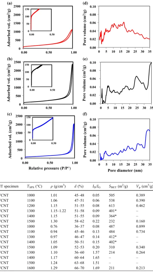
The CNT powders exhibit a N2sorption isotherm
(Fig.5 left-side panel) with a narrow hysteresis loop
at relative pressures from 0.7 to 1.0 and adsorbed
0 5 10 15 20 25 30 35 1 2 4 5 7 8 10 11 13 14 16 17 19 0 5 10 15 20 25 30 35 1 2 4 5 7 8 10 11 13 14 16 17 19 0 5 10 15 20 25 30 35 1 2 4 5 7 8 10 11 13 14 16 17 19 (a) (c) (b) (d) (f) (e)
Number of walls Diameter (nm)
Frequency (%) Frequency (%) Frequency (%) Frequency (%) Frequency (%) Frequency (%) 144 CNTs 163 CNTs 100 CNTs 0 5 10 15 20 25 30 35 40 1 3 5 7 9 11 13 15 17 19 0 5 10 15 20 25 30 35 40 1 3 5 7 9 11 13 15 17 19 0 5 10 15 20 25 30 35 40 1 3 5 7 9 11 13 15 17 19
Figure 3 Distribution of the number of walls for the CNTs in the a 3WCNT, b 4WCNT and c 8WCNT samples; distribution of the internal (open bars) and external (solid bars) diameters for the
CNTs in thed 3WCNT, e 4WCNT and f 8WCNT samples. The
volumes (1000–2500 m2/g) in line with other reports
for thin MWCNTs [35], DWCNTs [15, 36] and
SWCNTs [37, 38]. The shape of the isotherm and
specifically the presence of the hysteresis loop points to a type IV isotherm, one of the six types of isotherm recognized by the IUPAC classification and charac-teristic of mesoporous adsorbents (i.e., the pore size
diameter is in the range 2–50 nm) [39]. Observation of
the low-pressure domain (insets in Fig. 5) reveals
some microporosity. The mesopore size distributions
are very broad (Fig. 5 right-side panel), reflecting
mostly the inter-tube space in the specimen [15, 36].
The BET-specific surface area of the samples (SCNT—
Table 1) decreases upon the increase in number of
walls of the CNTs (534, 493 and 242 m2/g for
3WCNT, 4WCNT and 8WCNT, respectively), in agreement with calculations from geometrical data
(number of walls and diameter) [40].
Carbon nanotube monoliths
The density (q—Table 2) of the monoliths increases
upon the increase in the SPS temperature. An esti-mation of the relative density as if the samples were pure carbon, and thus calculated using the theoretical
density (q0—Table 1), gives values in the range
45–62% for 3WCNT, slightly lower (36–53%) for 4WCNT and slightly higher (57–70%) for 8WCNT. The values change only slightly if one takes into account the presence of some residual catalyst as noted above. Both values are nevertheless included in
Table 2. Note that no attempt was made to evaluate if
the proportion of residual catalyst changed upon SPS.
It has been reported [41, 42] that the heat-treatment of
the MWCNTs has to be performed at temperatures above 1800 °C (or 1500 °C) to be an efficient method for removing residual metals. The present SPS are performed a temperatures in the range 1000–1500 °C; therefore, any change would be very small. The
higher density values for the 8WCNTs could reflect
that their shorter length has favored packing. The difference between the 3WCNTs and 4WCNTs could be due to a higher stiffness for the latter. The Raman
spectra of the 4WCNT monoliths (Fig. 6) show little
change compared to the spectrum of the
corre-sponding 4WCNT powder sample (Fig. 4b). RBM
peaks (insets in Fig. 6) are still detected indicating the
continuous presence of small-diameter CNTs in all the 4WCNT monoliths. For some samples, 4W1200
(Fig. 6c) and 4W1500 (Fig. 6f), a weak band at
1720 cm-1 is detected. Upon closer inspection, it is
present but extremely weak on most spectra
includ-ing for the 4WCNT powder (Fig. 4b) and although it
is still unclear, it could reflect the presence of disor-dered carbon due to the influence of the local applied pressure on the different walls, including
amor-phization, ovalization and collapse [43–45]. The
Raman ID/IG ratio for the monoliths (Table 2) is
1100 1300 1500 1700 1100 1300 1500 1700 Intensity (a.u.) 1100 1300 1500 1700 Raman shift (cm-1) Raman shift (cm-1) Raman shift (cm-1) Intensity (a.u.) Intensity (a.u.) 100 150 200 250 300 100 150 200 250 300 (a) (c) (b)
Figure 4 Raman spectra of the a 3WCNT, b 4WCNT and
c 8WCNT samples. Insets are the low-frequency area showing radial breathing mode peaks.
0 500 1000 1500 2000 2500 0 500 1000 1500 2000 2500 0 500 1000 1500 2000 2500 0 5 10 15 20 25 30 35 0 5 10 15 20 25 30 35 0 5 10 15 20 25 30 35 0 50 100 150 0 50 100 150 0 50 100 150
Relative pressure (P/P°) Pore diameter (nm)
Adsorbed vol. (cm 3/g) Pore volume (cm 3/g) Adsorbed vol. (cm 3/g) Pore volume (cm 3/g) Adsorbed vol. (cm 3/g) Pore volume (cm 3/g) 0.00 0.50 1.00 0.00 0.50 1.00 0.00 0.50 1.00 0.00 0.50 0.00 0.50 0.00 0.50 0.10 0.08 0.06 0.04 0.00 0.02 0.10 0.08 0.06 0.04 0.00 0.02 0.10 0.08 0.06 0.04 0.00 0.02 (a) (d) (b) (e) (c) (f) Figure 5 N2adsorption– desorption isotherms (77 K) for thea 3WCNT, b 4WCNT
andc 8WCNT samples (insets
show the low-pressure range); pore size distribution as
deduced from N2desorption
curves for the CNTs in the d 3WCNT, e 4WCNT and f 8WCNT samples.
Table 2 Experimental data for the different monoliths: CNT specimen, SPS
temperature (TSPS), density
(q), relative density (d),
RamanID/IGratio, specific
surface area (SBET), porous volume (VP)
CNT specimen TSPS(°C) q (g/cm3) d (%) ID/IG SBET(m2/g) Vp(cm3/g)
3WCNT 1000 1.01 45–48 0.05 505 0.389 3WCNT 1100 1.06 47–51 0.06 538 0.390 3WCNT 1200 1.15 51–55 0.08 613 0.462 3WCNT 1300 1.15–1.22 51–58 0.09 401* – 3WCNT 1400 1.15 51–55 0.09 364* – 3WCNT 1500 1.30 58–62 0.22 232 0.160 4WCNT 1000 0.76 36–37 0.08 487 0.899 4WCNT 1100 0.94 45–46 0.13 484 0.734 4WCNT 1300 0.97 46–47 0.14 412* – 4WCNT 1400 1.05 50–51 0.15 402* – 4WCNT 1500 1.09 52–53 0.20 310 0.340 8WCNT 1300 1.10 56–60 1.57 214 0.264 8WCNT 1400 1.17 60–64 1.65 – – 8WCNT 1500 1.24 63–68 1.51 – – 8WCNT 1600 1.29 66–70 1.69 211 0.213
lower than that found prior to consolidation
(Table1), which could reflect the elimination of
sur-face defects and formational defects in the CNT outer walls by a thermal annealing effect during SPS.
Indeed, other authors [41,42,46] have reported that
oxygen functional groups can be selectively removed from a CNT surface and formational defects can anneal out at relatively low temperatures, below 1600 °C, whereas microstructural defects within the MWCNT structure require subsequent annealing at much higher temperatures (typically above 3000 °C).
The trend, however, is that the ID/IGratio increases
upon the increase in temperature and this density
(Fig.7). As mentioned above, this could also reflect
the presence of disordered material surrounding the
CNTs [26] and the limited formation of
amorphous-like carbon forms during the SPS treatment It has
been reported [47] that single-wall CNTs prepared by
arc-discharge, with a very narrow diameter distri-bution (in the range 1.33–1.52 nm), are progressively transformed into graphite-like and amorphous-like structures during the SPS process, the latter embed-ding the remaining CNT bundles. The general evo-lution should be the same in our case but using CNT samples with a distribution in diameters and number of walls and thus a distribution of defects along their length, any effect is more difficult to observe and anyway the Raman spectra show that the formation of amorphous-like structures during the SPS process is limited. 0 20 40 60 80 100 1100 1300 1500 1700 0 20 40 60 80 100 1100 1300 1500 1700 0 20 40 60 80 100 1100 1300 1500 1700 0 20 40 60 80 100 1100 1300 1500 1700 0 20 40 60 80 100 1100 1300 1500 1700 100 200 300 100 200 300 100 200 300 100 200 300 100 200 300 0 20 40 60 80 100 1100 1300 1500 1700 100 200 300 (a) (c) (b) (d) (f) (e)
Raman shift (cm-1) Raman shift (cm-1)
Raman shift (cm-1) Raman shift (cm-1)
Raman shift (cm-1) Raman shift (cm-1)
Intensity (a.u.) Intensity (a.u.) Intensity (a.u.) Intensity (a.u.) Intensity (a.u.) Intensity (a.u.)
Figure 6 Raman spectra of the 4WCNT monoliths: a 4W1000, b 4W1100, c 4W1200, d 4W1300, e 4W1400 and f 4W1500. Insets are the low-frequency area showing radial breathing mode peaks.
The CNT sorption isotherms of selected monoliths
are presented in Fig.8. The specific surface area
(SBET—Table2) for the 3W monoliths tends to
ini-tially slightly increase upon the increase in SPS
tem-perature, from 534 m2/g for 3WCNT to 613 m2/g for
3W1200, and then regularly decreases. For the 4W
monoliths, SBET stays constant ([ 480 m2/g) up to
4W1200 and then also regularly decreases down to
Density (m²/g) ID /IG ratio 0.6 0.8 1.0 1.2 1.4 0.25 0.20 0.15 0.10 0.00 0.05
Figure 7 RamanID/IGratio versus density for the
3WCNT(tri-angles) and 4WCNT(circles) monoliths. The dotted lines are guides to the eye.
0 50 100 150 200 250 300 350 400 450 500 550 600 Relative pressure (P/P°) Adsorbed volum e (cm 3/g) 0.00 0.20 0.40 0.60 0.80 1.00
Figure 8 N2adsorption–desorption isotherms (77 K) for selected
monoliths: 3W1000 (solid red), 3W1500 (dotted red), 4W1000 (solid black), 4W1500 (dotted black), 8W1300 (solid blue), 8W1600 (dotted blue). 0 4 8 12 16 20 0 4 8 12 16 20 0 4 8 12 16 20 Pore diameter (nm) 0.20 0.15 0.10 0.05 0.00 0.20 0.15 0.10 0.05 0.00 0.20 0.15 0.10 0.05 0.00 Pore volume (cm 3/g) Pore volume (cm 3/g) Pore volume (cm 3/g) 0.0 0.5 1.0 1.5 2.0 0.0 0.5 1.0 1.5 2.0 0.0 0.5 1.0 1.5 2.0 0.08 0.04 0.00 0.04 0.02 0.00 0.12 0.08 0.00 0.04 (a) (b) (c)
Figure 9 Pore size distribution as deduced from N2 desorption
curves for selected monoliths:a 3W1000 (solid red) and 3W1500
(dotted red),b 4W1000 (solid black) and 4W1500 (dotted black),
c 8W1300 (solid blue) and 8W1600 (dotted blue). Insets show the micropore range.
310 m2/g for 4W1500. SBETof 500 m2/g was reported
for spatially aligned arrays of large (inner diameter
equal to 8 mm) DWCNTs [36]. For the 8W monoliths
(ca. 210 m2/g), the decrease compared to the 8WCNT
powder (242 m2/g) is very moderate. The 4W1000
isotherm stands out because it still shows a hysteresis loop over a wide range of relative pressure, indicat-ing a wide range of mesopore sizes. It is widely accepted that there is a correlation between the shape of the hysteresis loop and the texture (pore size dis-tribution, pore geometry and connectivity) of a
mesoporous material [39]. Moreover, the adsorbed
volume (about 600 cm3/g) is markedly higher than
for the other monoliths. By contrast, the isotherm for 4W1500, like those for 3W1000, 3W1500, 8W1300 and
8W1600, shows a IUPAC classification H2 loop [39]
indicating materials that are often disordered, where the distribution of pore size and shape is not well defined and also indicative of bottleneck constrictions and interconnecting mesopores. The pore size distri-butions reveal that the 4W1000 monolith (solid line in
Fig.9b) retains mesopores over a wide range from 2
to over 20 nm, whereas the 4W1500 monolith (dotted
line in Fig.9b) and the 3W (Fig.9a) and the 8W
monoliths (Fig.9c) have a much narrower pore size
distribution, with a maximum diameter at 12, 10 or 6 nm depending on CNT sample and temperature.
The fact that other authors [15, 16] use the Barrett–
Joyner–Halenda (BJH) method for calculating the pore size distributions, as opposed to the NLDFT method here, makes it difficult to make comparisons. The BJH method is not fit for pore diameters below 1.7 nm. The volume adsorbed at very low pressure (micropores domain) is similar to that found prior to consolidation and the corresponding pore size
dis-tributions (insets in Fig.9) show two more or less
defined micropore ranges, 0.5–1.0 nm and
1.4–1.9 nm. This could reflect a partial opening of the
CNTs [37]. The present values for SBETand pore size
distribution are in line with the values reported for carbon monoliths for non-activated carbon (KOH-activation is known to increase the specific surface area and microporosity) and possible applications
could be as oil or gas sorbents [16,48–50]. The porous
volume (Vp—Table2) for 4W1000 (0.899 cm3/g) and
4W1100 (0.734 cm3/g) is, however, significantly (2–3
times) higher than for the other present monoliths
and those reported elsewhere [16, 49, 50]. Thus, it
appears that the 4WCNTs when consolidated into monoliths by SPS at 1000 or 1100 °C are able to
somewhat resist consolidation and to retain some high amount of mesoporosity above 10 nm which contributes to a high porous volume. Compared to
the 3WCNT monoliths with the same SBET but half
the porous volume, this could reflect a particular combination of CNT length, flexibility, proportion of defects as well as sample purity and deserves further studies.
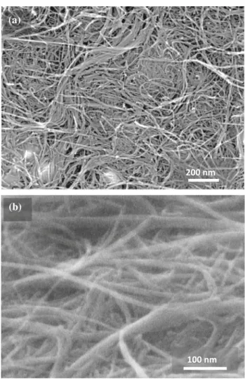
The 4W1500 monolith, with a narrow pores size
distribution (dotted line in Fig.9b), was selected for
further characterization. FESEM images of the top
surface (Fig. 10b) and cross section (Fig.10b) reveal
undamaged CNTs and CNT bundles. TEM images of the 4W1500 thin foil prepared by FIB are presented in
Fig.11. Bundles of 4WCNT are observed (between
the dashed lines in Fig.11a), indicating that they
were not destroyed by FIB milling, therefore vali-dating the method for subsequent TEM observations of CNT monoliths. Interestingly, no pores are
(a)
200 nm
100 nm
(b)
Figure 10 FESEM images of the 4W1500 monolith:a top-view
observed at this scale. Nanometric particles are also
evidenced (dark contrasts arrowed in Fig.11a).
Analysis of the EDS pattern (Fig.11b) of the
corre-sponding area reveals the presence of carbon, cobalt and molybdenum elements originating from the
CNTs and residual Co and Mo2C catalytic
nanopar-ticles. The detection of copper and platinum reflects the thin foil Cu support and to the FIB preparation involving a Pt deposit, respectively. Note that EDS is too local a probe for quantitative assessment of the content of residual catalyst in the monolith and, as noted above, that the present SPS temperatures are too low to massively remove the residual metals.
HRTEM images (Fig.11c, d) reveal pores between 2
and 10 nm in size, in good agreement with the cor-responding pore size distribution deduced from the
N2desorption curve (2–12 nm, dotted line in Fig.9b).
The cross sections of several FWCNTs are clearly
observed (Fig.11d), but it is not possible to prove that
they are open and contribute to the porosity. An
electron microdiffraction pattern (inset in Fig.11d)
recorded in an area devoid of nanoparticles presents four rings corresponding to the (002), (101), (004) and
(110) planes of graphite, reflecting the spatial disor-ganization of the 4WCNTs within the monolith.
Summary and conclusions
Carbon nanotubes with few walls (FWCNTs) are prepared by catalytic chemical vapor deposition. The average number of walls (3, 4 and 8) and the internal and external diameter distributions are determined from TEM images. The 3WCNTs and 4WCNTs pre-pared in-house show less defects than the commer-cial 8WCNTs. Binder-free FWCNTs monoliths are prepared by spark plasma sintering of the CNT powders at 1000–1600 °C. The high temperatures favor the elimination of surface defects of the FWCNT, although there is a progressive albeit lim-ited amorphization upon the increase in SPS tem-perature. No dramatic damage to the CNTs is detected by FESEM and HRTEM observations. Den-sification increases moderately upon the increase in SPS temperature and most monoliths show a density
close to about 1 cm3/g. (c) 20 nm (a) 5 nm (d) (002) (101) (004) (110) 5 nm (b)
Figure 11 TEM images of the 4W1500 monolith thin foil
showinga bundles of 4WCNT
(between the dashed lines) and nanometric particles (dark contrasts arrowed in the boxed
area);b EDS pattern of the
corresponding area;c and
d HRTEM images showing reveal pores 2–10 nm in size, and the cross sections of
several FWCNTs. Inset ind is
an electron microdiffraction pattern recorded in an area devoid of nanoparticles.
N2 adsorption–desorption cycles revealed that the
powders and monoliths show microporosity and, mostly, mesoporosity. The 3WCNT and 4WCNT monoliths sintered at 1000 and 1100 °C show a
specific surface area equal to about 500 m2/g, with
very little losses compared to the corresponding powders. Interestingly, the 4WCNT monoliths are able to retain a high amount of mesoporosity in the 10–20 nm range and thus they show a high porous
volume of the order of 0.8 cm3/g, twice the value
reported found for other CNT monoliths or foams. The difference between the 3WCNTs and 4WCNTs could reflect a particular combination of CNT length, flexibility and proportion of defects and warrants further studies.
Acknowledgements
The authors thank Ch. Chauvin for CNT synthesis and test samples preparation. Electron microscopy was performed at ‘‘Centre de microcaracte´risation
Raimond Castaing—UMS 3623’’ (Toulouse) and the
authors thank C. Josse and A. Descamps-Mandine for FIB preparation and help with the TEM observations. The SPS was performed at the Plateforme Nationale
CNRS de Frittage-Flash (PNF2, Toulouse). This work
is made in part under the contract ANR 2011-NANO-025 TRI-CO.
References
[1] Ma RZ, Xu CL, Wei BQ, Liang J, Wu DH, Li DJ (1999)
Electrical conductivity and field emission characteristics of hot-pressed sintered carbon nanotubes. Mater Res Bull 34:741–747
[2] Zhang HL, Li JF, Yao KF, Chen LD (2005) Spark plasma
sintering and thermal conductivity of carbon nanotube bulk materials. J Appl Phys 97:114310-1–114310-4
[3] Qin C, Shi X, Bai SQ, Chen LD, Wang LJ (2006) High
temperature electrical and thermal properties of the bulk carbon nanotube prepared by SPS. Mater Sci Eng A 420:208–211
[4] Yang K, He J, Su Z, Reppert JB, Skove MJ, Tritt TM, Rao
AM (2010) Inter-tube bonding, graphene formation and anisotropic transport properties in spark plasma sintered multi-wall carbon nanotube arrays. Carbon 48:756–762
[5] Zhang HL, Lia JF, Yao KF, Chen LD (2005) Spark plasma
sintering and thermal conductivity of carbon nanotube bulk materials. J Appl Phys 97:114310-1–114310-4
[6] Marinho B, Ghislandi M, Tkalya E, Koning CE, de With G
(2012) Electrical conductivity of compacts of graphene, multi-wall carbon nanotubes, carbon black, and graphite powder. Powder Technol 221:351–358
[7] Cha SI, Kim KT, Lee KH, Mo CB, Jeong YJ, Hong SH
(2008) Mechanical and electrical properties of cross-linked carbon nanotubes. Carbon 46:482–488
[8] Li JL, Bai GZ, Feng JW, Jiang W (2005) Microstructure and
mechanical properties of hot-pressed carbon nanotubes compacted by spark plasma sintering. Carbon 43:2649–2653
[9] Li JL, Wang LJ, He T, Jiang W (2007) Surface graphitization
and mechanical properties of hot-pressed bulk carbon nan-otubes compacted by spark plasma sintering. Carbon 45:2636–2642
[10] Yamamoto G, Sato Y, Takahashi T, Omori M, Okubo A, Tohji K, Hashida T (2006) Mechanical properties of binder-free single-walled carbon nanotubes solids. Scr Mater 54:299–303
[11] Wang W, Yokoyama A, Liao S, Omori M, Zhu Y, Uo M, Akasaka T, Watari F (2008) Preparation and characteristics of a binderless carbon nanotube monolith and its biocom-patibility. Mater Sci Eng C 28:1082–1086
[12] Uo M, Hasegawa T, Akasaka T, Tanaka I, Munekane F, Omori M, Kimura H, Nakatomi R, Soga K, Kogo Y, Watari F (2009) Multiwalled carbon nanotube monoliths prepared by spark plasma sintering (SPS) and their mechanical properties. Bio-Med Mater Eng 19:11–17
[13] Sato Y, Nishizaka H, Sawano S, Yoshinaka A, Hirano K, Hashiguchi S, Arie T, Akita S, Yamamoto G, Hashida T, Kimura H, Motomiya K, Tohji K (2012) Influence of the structure of the nanotube on the mechanical properties of binder-free multi-walled carbon nanotube solids. Carbon 50:34–39
[14] Amadou J, Begin D, Nguyen P, Tessonnier JP, Dintzer T, Vanhaecke E, Ledoux MJ, Pham-Huu C (2006) Synthesis of a carbon nanotube monolith with controlled macroscopic shape. Carbon 44:2587–2592
[15] Laurent Ch, Chevallier G, Weibel A, Peigney A, Estourne`s C (2008) Spark plasma sintering of double-walled carbon nanotubes. Carbon 46:1812–1816
[16] Liu YF, Ba H, Nguyen DL, Ersen O, Romero T, Zafeiratos S, Begin D, Janowska I, Pham-Huu C (2013) Synthesis of porous carbon nanotubes foam composites with a high accessible surface area and tunable porosity. J Mater Chem A 1:9508–9516
[17] Chiodarelli N, Richard O, Bender H, Heyns M, De Gendt S, Groeseneken G, Vereecken PM (2012) Correlation between
number of walls and diameter in multiwall carbon nanotubes grown by chemical vapor deposition. Carbon 50:1748–1752 [18] Preston C, Song D, Taillon J, Cumings J, Hu L (2016) Boron-doped few-walled carbon nanotubes: novel synthesis and properties. Nanotechnology 27:445601-1–445601-9 [19] Jeong HJ, Kim KK, Jeong SY, Park MH, Yang CW, Lee YH
(2004) High-yield catalytic synthesis of thin multiwalled carbon nanotubes. J Phys Chem B 108:17695–17698 [20] Lukic B, Seo JW, Bacsa RR, Delpeux S, Be´guin F, Bister G,
Fonseca A, Nagy JB, Kis A, Jeney S, Kulik AJ, Forro L (2005) Catalytically grown carbon nanotubes of small diameter have a high Young’s modulus. Nano Lett 5:2074–2077
[21] Qian C, Qi H, Gao B, Cheng Y, Qiu Q, Zhou O, Liu JJ (2006) Fabrication of small diameter few-walled carbon nanotubes with enhanced field emission property. J Nanosci Nanotechnol 6:1346–1349
[22] Hou Y, Tang J, Zhang HB, Qian C, Feng YY, Liu J (2009) Functionalized few-walled carbon nanotubes for mechanical
reinforcement of polymeric composites. ACS Nano
3:1057–1062
[23] Flahaut E, Peigney A, Bacsa WS, Bacsa RR, Laurent Ch (2004) CCVD synthesis of carbon nanotubes from (Mg Co, Mo)O catalysts: influence of the proportions of cobalt and molybdenum. J Mater Chem 14:646–653
[24] Flahaut E, Laurent Ch, Peigney A (2005) Catalytic CVD synthesis of double and triple-walled carbon nanotubes by the control of catalyst preparation. Carbon 43:375–383 [25] Flahaut E, Peigney A, Laurent Ch, Rousset A (2000)
Syn-thesis of single-walled carbon nanotubes –Co–MgO com-posite powders and extraction of the nanotubes. J Mater Chem 10:49–52
[26] Osswald S, Flahaut E, Gogotsi Y (2005) Elimination of D-band in Raman spectra of double-wall carbon nanotubes by oxidation. Chem Phys Lett 402:422–427
[27] Bortolamiol T, Lukanov P, Galibert AM, Soula B, Lon-chambon P, Datas L, Flahaut E (2014) Double-walled carbon nanotubes: quantitative purification assessment, balance between purification and degradation and solution filling as an evidence of opening. Carbon 78:79–90
[28] Guiderdoni Ch, Pavlenko E, Turq V, Weibel A, Puech P, Estourne`s C, Peigney A, Bacsa W, Laurent Ch (2013) The preparation of carbon nanotube (CNT)/copper composites and the effect of the number of CNT walls on their hardness, friction and wear properties. Carbon 58:185–197
[29] Flahaut E, Peigney A, Laurent C (2003) Double-walled carbon nanotubes in composite powders. J Nanosci Nan-otechnol 3:151–158
[30] Peigney A, Laurent Ch, Dobigeon F, Rousset A (1997) Carbon nanotubes grown in situ by a novel catalytic method. J Mater Res 12:613–615
[31] Cordier A, de Resende VG, Weibel A, De Grave E, Peigney A, Laurent Ch (2010) Catalytic chemical vapor deposition synthesis of double-walled and few-walled carbon nanotubes
by using a MoO3-supported conditioning catalyst to control
the formation of iron catalytic particles within a
a-Al1.8-Fe0.2O3 self-supported foam. J Phys Chem C
114:19188–19193
[32] Kasperski A, Weibel A, Datas L, De Grave E, Peigney A, Laurent Ch (2015) Large-diameter single-wall carbon nan-otubes formed alongside small-diameter double-walled car-bon nanotubes. J Phys Chem C 119:1524–1535
[33] Zhang Q, Yu H, Liu Y, Qian W, Wang Y, Luo G, Wei F (2008) Few walled carbon nanotube production in large-scale by nano-agglomerate fluidized-bed process. NANO 3:45–50
[34] Laurent Ch, Flahaut E, Peigney A (2010) The weight and density of carbon nanotubes versus the number of walls and diameter. Carbon 48:2994–2996
[35] Kim DY, Yang CM, Park YS, Kim KK, Jeong SY, Han JH, Lee YH (2005) Characterization of thin multi-walled carbon nanotubes synthesized by catalytic chemical vapor deposi-tion. Chem Phys Lett 413:135–141
[36] Babu DJ, Lange M, Cherkashinin G, Issanin A, Staudt R,
Schneider JJ (2013) Gas adsorption studies of CO2and N2in
spatially aligned double-walled carbon nanotube arrays. Carbon 61:616–623
[37] Yang CM, Kaneko K, Yudasaka M, Iijima S (2002) Effect of purification on pore structure of HiPco single-walled carbon nanotube aggregates. Nano Lett 2:385–388
[38] Hu YH, Ruckenstein E (2004) Pore size distribution of single-walled carbon nanotubes. Ind Eng Chem Res 43:708–711
[39] Sing KSW, Everett DH, Haul RAW, Moscou L, Pierotti RA,
Rouquerol J, Siemieniewska T (1985) Reporting
physisorption data for gas/solid systems with special refer-ence to the determination of surface area and porosity. Pure Appl Chem 57:603–619
[40] Peigney A, Laurent Ch, Flahaut E, Bacsa RR, Rousset A (2001) Specific surface area of carbon nanotubes and bun-dles of carbon nanotubes. Carbon 39:507–514
[41] Andrews R, Jacques D, Qian D, Dickey EC (2001) Purifi-cation and structural annealing of multiwalled carbon nan-otubes at graphitization temperatures. Carbon 39:1681–1687 [42] Huang W, Wang Y, Luo G, Wei F (2003) 99.9% purity multi-walled carbon nanotubes by vacuum high-temperature annealing. Carbon 41:2585–2590
[43] Goncharov AF, Andreev VD (1991) Raman scattering in carbon films at high pressures. Sov Phys JETP 73:140–142 [44] Aguiar AL, Capaz RB, Souza Filho AG, San-Miguel A (2012) Structural and phonon properties of bundled single-and double-wall carbon nanotubes under pressure. J Phys Chem C 116:22637–22645
[45] Puech P, Hubel H, Dunstan DJ, Bacsa RR, Laurent C, Bacsa WS (2004) Discontinuous tangential stress in doublewall carbon nanotubes. Phys Rev Lett 93:095506-1–095506-4 [46] Baaziz W, Begin-Colin S, Pichon BP, Florea I, Ersen O,
Zafeiratos S, Barbosa R, Begin D, Pham-Huu C (2012) High density monodisperse cobalt nanoparticles (NPs) filling of multi-walled carbon nanotubes. Chem Mater Commun 24:1549–1551
[47] Yamamoto G, Sato Y, Takahashi T, Omori M, Hashida T, Okubo A, Tohji K (2006) Single-walled carbon nanotube-derived novel structural material. J Mater Res 21:1537–1542 [48] Du R, Zhao Q, Zhang N, Zhang J (2015) Macroscopic
car-bon nanotube-based 3D monoliths. Small 11:3263–3289 [49] Klepel O, Danneberg N, Dra¨ger M, Erlitz M, Taubert M
(2016) Synthesis of porous carbon monoliths using hard templates. Materials 9:1–14
[50] Gupta J, Tai NH (2016) Carbon materials as oil sorbent: a review on the synthesis and performance. J Mater Chem A 4:1550–1565