HAL Id: inria-00465061
https://hal.inria.fr/inria-00465061v2
Submitted on 13 Apr 2010
Technical Report on Formal Development of
Two-Electrode Cardiac Pacing System
Dominique Méry, Neeraj Kumar Singh
To cite this version:
Dominique Méry, Neeraj Kumar Singh. Technical Report on Formal Development of Two-Electrode
Cardiac Pacing System. [Research Report] 2010. �inria-00465061v2�
Technical Report on Formal Development of
Two-Electrode Cardiac Pacing System
Dominique M´
ery
E-mail: mery@loria.fr
Neeraj Kumar Singh
E-mail: neerajkumar.singh@loria.fr
LORIA
Universit´
e Henri Poincar´
e Nancy 1
BP 239
54506 Vandœuvre-l`
es-Nancy
April 13, 2010
Abstract
To build a high quality and zero defects medical devices and softwares is a crucial task. Formal modeling techniques help to achieve this tar-get at certain level. Formal modeling of High-Confidence Medical devices those are too much error prone in operating, are an International Grand Challenge in the area of Verified Software. Formal modeling of an arti-ficial pacemaker is also one of the proposed challenge. The architecture and functional behaviour of the double electrode pacemaker is more com-plex than the single electrode pacemaker. Proof-based an incremental approach, we use to develop the formal model of functional behaviour of the double electrode pacemaker. The incremental proof-based develop-ment is mainly driven by the refinedevelop-ment between an abstract model of the system and its detailed design through a series of refinements, which adds parametric based functional properties to the abstract system-level speci-fications using some intermediate models. The properties express system architecture and action-reaction under real-time constraints. This techni-cal report focuses on the formal development of the double electrode oper-ating modes and finds the common architecture of operoper-ating modes in tree form that helps to make the consistent system. The Event B modeling language is used to express the double electrode pacemaker and generated proof obligations are proved by RODIN platform. Finally, the pacemaker model has been validated by an Event B animator; ProB tool.
1
Introduction
The high confidence medical devices are highly dependent on the performance, the need for absolute precision can be a life or death issue. So, after a long time due to many failure cases and untrustworthiness of the medical devices, the equipment manufacturers have turned towards formalism in the engineering of medical device. For decades, software failures have costed billions of dollars a year [37]. Software failures and lack of warranties of products have emerged the software crisis. Due to software crisis, various formalism and rigourous techniques (VDM, Z, Event-B, Alloy etc.) have been used in the development process of safety-critical systems. These approaches provide the certain level of reliability and confidence to develop the error free systems. Formal methods and their tools have achieved a certain level of usability that could be applied even in industrial scale applications allowing software developers to provide more meaningful guarantees to their projects.
The high confidence medical devices are too complex in operating and sev-eral concurrent process are running together. To validate such kind of system, only simulation and testing can be usual techniques. By nature, testing can be applied only after a prototype implementation of the system has been realized. Formal verification, as opposed to testing, works on models (rather than imple-mentation) and amounts of mathematical proofs provide correctness of a given system that can be realized the actual system in early stage of development.
Tony Hoare suggested a Grand Challenges for Computing Research [24] to in-tegrate the research community to work together towards a common goal, agreed to be valuable and achievable by a team effort within a predicted timescale. Ver-ification Grand Challenges is one of them. From the VerVer-ification Grand Chal-lenges, many application areas were proposed by the Verified Software Initiative [23]. The pacemaker specification [13, 20, 2] has been proposed by the soft-ware quality research laboratory at McMaster University as a pilot project for the Verified Software Initiative [38, 30]. The challenge is characterised by sys-tem aspects including hardware requirements and safety issues. Such a syssys-tem demands high integrity to achieve safety requirements.
In order to analyze the problem, we consider the triptych by D. Bjoerner [11], where,
D, S → R
D = Healthcare domain
S = Model or chain of models of the pacemaker system
H.D. Macedo, et al. [30] have developed a distributed real-time model of a cardiac pacing system but the development was not based on proof and refine-ment techniques. Similarly, in other case study V.P. Manna, et al. [32] have developed a simple pacemaker implementation. Recently, Gomes et al [21] wrote a formal specification of the pacemaker system using the Z modelling language. According to the paper, they have modelled the sequential model similar to H.D. Macedo et al. work [30]. In this report, we have specially cov-ered the bradycardia operating modes of the double electrode pacemaker. We have developed the parametric and functional based incremental development of bradicardia operating modes. Moreover, we have added the threshold, and rate adaptive bradicardia operating modes. Incremental development is based on refinement approach and at every level of the development, we have proved the all required safety properties (refinement and consistency checking). Other specifications [30, 21] of the pacemaker developed as a one shot model, means those are not based on the refinement.
Our approach is based on the Event B modelling language which is sup-ported by the RODIN platform integrating tools for proving models and refine-ments of models; moreover we use the ProB tool [34, 28] for analyzing the mod-els and for validating these modmod-els. Here we present a stepwise development to model and verify such interdisciplinary requirements in Event B [14, 4]. The correctness of each step is proved in order to achieve a reliable system. The pacemaker models must be validated to ensure that they meet the require-ments of the pacemaker. Hence, validation must be carried out by both formal modeling and domain experts. The abstract model includes event modeling of bradycardia operating modes of a double electrode pacemaker system.
The refinement is supported by the RODIN [35] platform guarantees the preservation of safety properties. Thus, the behavior of the final system is pre-served by an abstract model as well as in the correctly refined models. Proof-based development methods [4] integrate formal proof techniques in the devel-opment of software systems. The main idea is to start with an abstract model of the given system. Details are gradually added to this first abstract model by building a sequence of more concrete events. The relationship between two suc-cessive models in this sequence is refinement [4, 6]. The current work intends to explore those problems related to the modeling of bradycardia operating modes using a double electrode pacemaker system under real time constraints and to evaluate the refinement process.
The outline of the remaining report is as follows: Basic outline of a pace-maker and a heart system are given in Section 2. The modelling framework is presented in Section 3. Section 4 explores the refinement based formal develop-ment of the double electrode pacemaker. The pacemaker models are validated by the ProB tool [34, 28] and correctness of the system are analyzed by gen-erated proof obligations (see Table-3) in Section 5. Finally, in Section 6, we conclude the report with some lessons learned from this experience and some prospective along with direction for future work.
2
Basic Overview of Pacemaker system
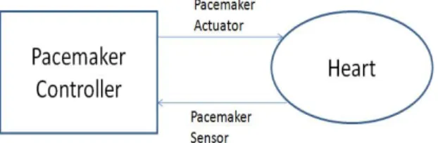
In Fig. 1 a suitable interface block diagram of the pacemaker and the heart is given. The conventional pacemakers serve two major functions, namely pacing and sensing. The pacemaker actuator is pacing by the delivery of a short, intense electrical pulse into the heart. However the pacemaker sensor uses the same electrode to detect the intrinsic activity of the heart. So, the pacemaker function of pacing and sensing activities are dependent on the behavior of the heart. The sensing and pacing functions regulates the heart rhythm. In this report, we present only the formal models of the double electrode pacemaker.
Fig. 1 Pacemaker and Heart Interface
The pacemaker system is a small electronic device that helps the heart to maintain the regular heart beat. The pacemaker is implanted in the chest during surgery. Wires called leads are put into the heart muscle. The device with the battery is placed under the skin, below the shoulder. In this study, the pacemaker is treated as an embedded system operating in an environment containing the heart. We first review the heart system that interact with the pacemaker (Section 2.1) and then consider elements of the pacemaker system itself (Section 2.2).
2.1
The Heart System
The human heart is wondrous in its ability to pump blood to the circulatory system continuously throughout a lifetime. The heart consists of four chambers: right atria, right ventricle, left atria and left ventricle, which contract and relax periodically. Atria form one unit and ventricles form another. The heart’s mechanical system (the pump) requires at the very least impulses from the electrical system. An electrical stimulus is generated by the sinus node (see Fig. 2), which is a small mass of specialized tissue located in the right atrium of the heart. This electrical stimulus travels down through the conduction pathways and causes the heart’s lower chambers to contract and pump out blood. The right and left atria are stimulated first and contract for a short period of time
Fig. 2 Heart or Natural Pacemaker [1]
An artificial pacemaker is implanted to assist the natural pacemaker or heart in case of a arrhythmias condition to control the heart rate [31]. Arrhythmias are due to cardiac problems producing abnormal heart rhythms. In general arrhythmias reduce heamodynamic performance including situations where the heart’s natural pacemaker develops an abnormal rate or rhythm or when normal conduction pathways are interrupted and a different part of the heart takes over control of the rhythm. An arrhythmia can involve an abnormal rhythm increase (tachycardia; > 100 bpm) or decrease (bradycardia; < 60 bpm), or may be characterized by an irregular cardiac rhythm, e.g. due to asynchrony of the cardiac chambers. The irregularity of the heartbeat, called bradycardia and techycardia. The bradycardia indicates that the heart rate falls below the expected level while in techycardia indicates that the heart rate go above the expected level of the heart rate. An artificial pacemaker can restore synchrony between the atria and ventricles. In an artificial pacemaker system, the firmware controls the hardware such that an adequate heart rate is maintained, which is necessary either because the heart’s natural pacemaker is insufficiently fast or slow or there is a block in the heart’s electrical conduction system [7, 18, 22, 27, 29, 31]. Beats per minute (bpm) is a basic unit to measure the rate of heart activity.
2.2
The Pacemaker system
The basic elements of the pacemaker system [7, 18] are:
1. Leads: One or more flexible coiled metal wire normally two, that trans-mits electrical signals between the heart and the pacemaker. Each pace-maker lead is classified by its configuration: either one (“unipolar”) or two (“bipolar”) separated points of electrical contact with the heart.
2. The Pacemaker Generator: The pacemaker is both the power source and the brain of the pacing and sensing systems. It contains an implanted battery and controller as an electronic circuitry.
Category Chambers Chambers Response to Rate Modulation Paced Sensed Sensing
Letters O-None O-None O-None R-Rate Modulation A-Atrium A-Atrium T-Triggered
V-Ventricle V-Ventricle I-Inhibited D-Dual(A+V) D-Dual(A+V) D-Dual(T+I)
Table-1 Bradycardia operating modes of pacemaker system
3. Device Controller-Monitor (DCM) or Programmer: An external unit that interacts with the pacemaker device using a wireless connection. It consists of a hardware platform and the pacemaker application software. 4. Accelerometer: It is an electromechanical device inside the pacemaker that measures the body motion or acceleration of motion of a body in order to allow modulated pacing.
In the double electrode pacemaker, the electrode is attached to the right atrium or the right ventricle. It has several operational modes that regulate the heart functioning. The specification document [13] describes all possible operating modes that are controlled by the different programmable parameters of the pacemaker. All the programmable parameters are related to real-time and action-reaction constraints, that is used to regulate the heart rate.
In order to understand the “language” of pacing, it is necessary to compre-hend the coding system that produced by a combined working party of the North American Society of Pacing and Electrophysiology (NASPE) and the British Pacing and Electrophysiology Group (BPEG) known as NBG(NASPE/BPEG generic) code [33]. This is a code of five letters of which the first three are most often used. The code provides a description of the pacemaker pacing and sensing functions. The sequence is referred to as “bradycardia operating modes”(see Table-1). In practice, only the first three or four-letter positions are commonly used to describe bradycardia pacing functions. The first letter of the code indicates which chambers are being paced, the second letter indi-cates which chambers are being sensed, the third letter of the code indiindi-cates the response to sensing and the final letter, which is optional indicates the pres-ence of rate modulation in response to the physical activity measured by the accelerometer. Accelerometer is an additional sensor in the pacemaker system that detects a physiological result of exercise or emotion and increase the pace-maker rate on the basis of a programmable algorithms. “X” is a wildcard used to denote any letter (i.e. “O”, “A”, “V” or “D”). T riggered (T ) refers to deliver a pacing stimulus and Inhibited (I) refers to an inhibition from further pacing
3
The modelling framework
Here, we will summarize the concepts of the Event B modelling language developed by Abrial [14, 4] and will indicate the links with the tool called RODIN [35]. The modelling process deals with various languages, as seen by considering the triptych of Bjoerner [8, 9, 10, 12]: D, S −→ R. Here, the do-main D deals with properties, axioms, sets, constants, functions, relations, and theories. The system model S expresses a model or a refinement-based chain of models of the system. Finally, R expresses requirements for the system to be designed. Considering the Event B modelling language, we notice that the language can express safety properties, which are either invariants or theorems in a machine corresponding to the system. Recall that two main structures are available in Event B :
• Contexts express static information about the model.
• Machines express dynamic information about the model, invariants, safety properties, and events.
A Event B model is defining either a context or a machine. The triptych of Bjoerner [8, 9, 10, 12] D, S −→ R is translated as follows: C, M −→ R, where C is a context, M is a machine and R are the requirements. The relation −→ is defined to be a satisfaction relation with respect to an underlying logico-mathematical theory. This satisfaction relation is supported by the RODIN platform. A machine is organizing events modifying state variables and it uses static informations defined in a context. These basic structure mechanisms are extended by the refinement mechanism which provides a mechanism for relating an abstract model and a concrete model by adding new events or by adding new variables. This mechanism allows us to develop gradually Event B models and to validate each decision step using the proof tool. The refinement relationship should be expressed as follows: a model M is refined by a model P , when P is simulating M . The final concrete model is close to the behaviour of real system that is executing events using real source code. We give details now on the definition of events, refinement and guidelines for developing complex system models.
3.1
Modelling actions over states
The event-driven approach [3, 14, 4] is based on the B notation. It extends the methodological scope of basic concepts to take into account the idea of formal models. Briefly, a formal model is characterized by a (finite) list x of state variables possibly modified by a (finite) list of events, where an invariant I(x) states properties that must always be satisfied by the variables x and maintained by the activation of the events. In the following, we summarize the definitions and principles of formal models and explain how they can be managed by tools [5, 16, 35].
Generalized substitutions are borrowed from the B notation. They provide a means to express changes to state variable values. In its simple form x := E(x), a generalized substitution looks like an assignment statement. In this construct, x denotes a vector built on the set of state variables of the model, and E(x) denotes a vector of expressions. Here, however, the interpretation we shall give to this statement is not that of an assignment statement. We interpret it as a logical simultaneous substitution of each variable of the vector x by the corresponding expression of the vector E(x). There exists a more general normal form of this, denoted by the construct x : |(P (x, x0)). This should be read as x is modified in such a way that the value of x afterwards, denoted by x0, satisfies the predicate P (x, x0), where x0 denotes the new value of the vector and x denotes its old value. This is clearly nondeterministic in general.
An event has two main parts, namely, a guard, which is a predicate built on the state variables, and an action, which is a generalized substitution. An event can take one of three normal forms. The first form (BEGIN x : |(P (x, x0) END) shows an event that is not guarded, being therefore always enabled and se-mantically defined by P (x, x0). The second form (WHEN G(x) THEN x : |(Q(x, x0))
END) and third form (ANY t WHERE G(t, x) THEN x : |(R(x, x0, t)) END) are guarded by a guard that states the necessary condition for these events to
occur. The guard is represented byWHENG(x) in the second form, and by ANY t WHERE G(t, x) (for ∃ t · G(t, x)) in the third form. We note that the third form defines a possibly nondeterministic event where t represents a vector of distinct local variables. The before–after predicate BA(x, x0), associated with each of the three event types, describes the event as a logical predicate expressing the relationship linking the values of the state variables just before (x) and just after (x0) the execution of event EVENT evt. The second and the third forms are semantically equivalent to G(x) ∧ Q(x, x0) resp. ∃ t· (G(t, x) ∧ R(x, x0, t). Table-2 summarizes the three possible forms for writing a B event:
Proof obligations (INV 1 and INV 2) are produced by the RODIN tool [35] from events to state that an invariant condition I(x) is preserved. Their gen-eral form follows immediately from the definition of the before–after predicate BA(e)(x, x0) of each event e (see Table-2). Note that it follows from the two guarded forms of the events that this obligation is trivially discharged when the guard of the event is false. Whenever this is the case, the event is said to be disabled. The proof obligation FIS expresses the feasibility of the event e with respect to the invariant I.
3.2
Model refinement
Event e Before-after Predicate BA(e)(x,x’) BEGIN x : |(P (x, x0)) END P (x, x0) WHEN G(x) THEN x : |(Q(x, x0)) END G(x) ∧ Q(x, x0) ANY t WHERE G(t, x) THEN x : |(R(x, x0, t)) END ∃ t· ( G(t, x) ∧ R(x, x0, t) ) Proof obligations
• (INV1) Init(x) ⇒ I(x)
• (INV2) I(x) ∧ BA(e)(x, x0) ⇒ I(x0)
• (FIS) I(x) ∧ grd(e)(x) ⇒ ∃y.BA(e)(x, y)
(x) and concrete (y) state variables are linked by means of a gluing invariant J (x, y). A number of proof obligations ensure that (1) each abstract event is correctly refined by its corresponding concrete version, (2) each new event refines skip, (3) no new event takes control for ever, and (4) relative deadlock freedom is preserved. Details of the formulation of these proofs follows.
We suppose that an abstract model AM with variables x and invariant I(x) is refined by a concrete model CM with variables y and gluing invariant J (x, y). If BA(e)(x, x0) and BA(f )(y, y0) are respectively the abstract and concrete before– after predicates of the same event, e and f respectively, we have to prove the following statement, corresponding to proof obligation (1):
I(x) ∧ J (x, y) ∧ BA(f )(y, y0) ⇒ ∃x0· (BA(e)(x, x0) ∧ J (x0, y0))
Now, proof obligation (2) states that BA(f )(y, y0) must refine skip (x0= x),
generating the following simple statement to prove (2).
I(x) ∧ J (x, y) ∧ BA(f )(y, y0) ⇒ J (x, y0)
In refining a model, an existing event can be refined by strengthening the guard and/or the before–after predicate (effectively reducing the degree of non-determinism), or a new event can be added to refine the skip event. The fea-sibility condition is crucial to avoiding possible states that have no successor, such as division by zero. Furthermore, this refinement guarantees that the set of traces of the refined model contains (up to stuttering) the traces of the re-sulting model. The refinement of an event e by an event f means that the event f simulates the event e.
The Event B modelling language is supported by the RODIN platform [35] and has been introduced in publications [4, 14], where there are many case studies and discussions about the language itself and the foundations of the Event B approach. The language of generalized substitutions is very rich, en-abling the expression of any relation between states in a set-theoretical context. The expressive power of the language leads to a requirement for help in writing relational specifications, which is why we should provide guidelines for assisting the development of Event B models.
3.3
Guidelines for Event B Modelling
Considering design patterns [19], the purpose is to capture structures and to make decisions within a design that are common to similar modeling and analysis tasks. They can be re-applied when undertaking similar tasks in order to reduce
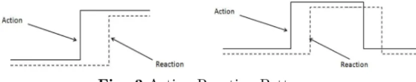
The pacemaker systems are characterized by their functions, which can be expressed by analyzing action-reaction and real time patterns. Sequences of inputs are recognized, and outputs can be emitted in response within a fixed time interval. So, the most common elements in pacemaker system are bounded time interval for every action, reaction and reaction pair. The action-reaction within a time limit can be viewed as an abstraction of the pacemaker system. We recognize the following two design patterns when modeling this kind of system according to the relationship between the action and corresponding reaction.
Under action-reaction chapter [4] two basic types of design patterns are, Action and Weak Reaction: Once an action emits, a reaction should start in response. For a quick instance, if an action stops, the reaction should follow. Sometimes reaction does not change immediately according to the action because the action moves too quickly (the continuance of an action is too short, or the interval between actions is too short). This is known as pattern of action and weak reaction.
Action and Strong Reaction: For every action, there is a corresponding reaction. To keep proper synchronization between action and corresponding reaction, known as pattern of action and strong reaction.
Fig. 3 Action-Reaction Patterns
The action-reaction events of a pacemaker system are based on the time constraint pattern in IEEE 1394 proposed by Cansell et. al and on the 2-Slots Simpson Algorithm case studies [15, 36]. This time pattern is fully based on timed automaton. The timed automaton is a finite state machine that is use-ful to model components of real-time systems. In a model, timed automata interacts with each other and defines a timed transition system. Besides ordi-nary action transitions that can represent input, output and internal actions. A timed transition system has time progress transitions. Such time progress transitions result in synchronous progress of all clock variables in the model. Here we apply the time pattern in modeling to synchronize the sensing and pacing stimulus functions of the pacemaker system in continuous progressive time constraint. In the model, events are controled under time constraints, which means action of any event activates only when time constraint satisfies on specific time. The time progress is also an event, so there is no modification of the underlying Event B language. It is only a modeling technique instead of a specialized formal system. The timed variable is in N (natural numbers) but time constraint can be written in terms involving unknown constants or expressions between different times. Finally, the timed event observations can be constrained by other events which determine future activations.
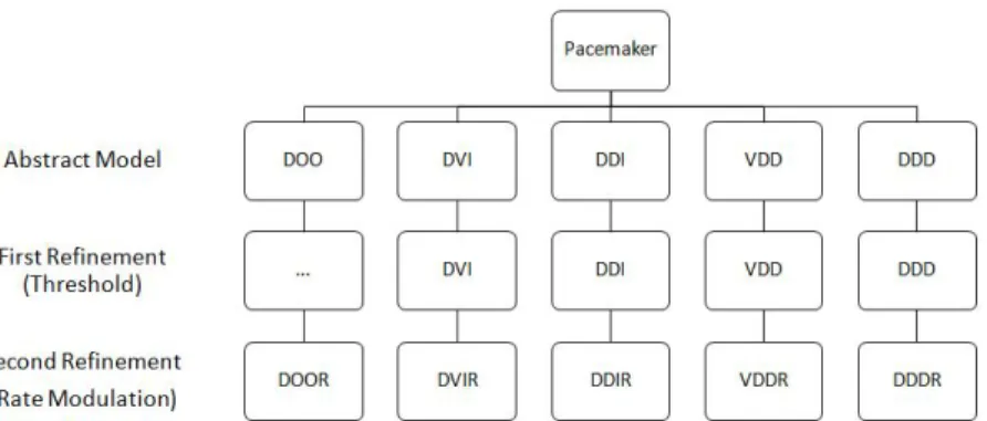
Fig. 4 Refinement structure of the double electrode pacemaker operating modes
4
Formal Development
The two electrode pacemaker system is more complex than one electrode pace-maker system. We have designed the block diagram (see Fig. 4) of hierarchical tree structure of the possible operating modes of the double electrode pace-maker. The hierarchical tree structure shows the stepwise refinement from ab-stract to concrete model. Each level of refinement introduces the new features of pacemaker as functional and parametric requirements. The root of this tree indicates the double electrode pacemaker. In a double electrode pacemaker, two electrodes are placed in both chambers; atrium and ventricular. These atrium and ventricular are the right atrium and ventricular. The next five branches of tree show the five opearting modes; DOO, DVI, DDI, VDD, and DDD (see Table-1). In thses operating modes, the pacemaker uses the both electrodes to pace in both chambers synchronously. It is an abstract level of the model. In the abstract model, we introduce all the operating modes abstractly with required properties of the pacemaker. From first refinement to last refinement, there is only one branch in every operating modes of the atrium and the ven-tricular chambers. The subsequent refinement models introduce all detailed information for the resulting system. Every refinement level shows an extension of previous operating modes as an introduction of a new feature or functional requirement. the triple dots (...) represents that there is no refinement at that level in particular operating mode (DOO). In abstract level and first refinement level, we have similar operating modes. But in the second refinement level, we have achieved the additional rate adaptive operating modes(i.e.DOOR, DVIR, DDIR, VDDR and DDDR). These operating modes are different from the
previ-with the help of action-reaction and real-time pattern using some initial events (Actuator ON A, Actuator OF F A, Actuator ON V , Actuator OF F V , Sensor ON A, Sensor OF F A, Sensor ON V , Sensor OF F V , tic, tic AV ). • Refinement 1 : Introduces the threshold parameter to filter the exact
sensing value within a sensing period to control the sensing and the pacing event and introduces more invariants to satisfy the pacing and sensing requirements of the system in both chambers.
• Refinement 2 : Introduces the accelerometer sensor component and rate modulation function to achieve the new rate adaptive operating modes of the pacemaker.
We have presented here only selected parts of our formalization and omit proof details.
4.1
The Context and Initial Model
In this section we describe the formal development of initial modes of double electrode cardiac pacemaker system. In the abstract model, we introduce the basic notions of action-reaction and real-time constraints using actuator and sensor in different heart chambers. In this abstraction, we begin with an ab-stract model of a double electrode cardiac pacemaker system focusing on pacing and sensing modes properties and operations control the pumping rate of nat-ural pacemaker or human heart. However, some pacing modes related to rate modulation are not described in this level. Instead they will emerged into final refinement. Thus, in this level, for every modes of pacemaker are treated in the same way as common basic modes, which are essential for the double electrode cardiac pacemaker. The model consists of several modules, each corresponding to an operating mode of the pacemaker. Here, we define the required context and then abstraction of the double electrode cardiac pacemaker system.
We begin by defining the Event-B context. The context uses the sets and con-stants to define the axioms and theorems. The axioms and theorems represent the logical formulation of the system. The logical formulation is the constant behaviour and the set of properties of the system. In the context, we define the constants LRL and U RL that relate to the lower rate limit (LRL) (mini-mum number of pace pulses delivered per minute by pacemaker) and upper rate limit (URL) (how fast the pacemaker will allow the heart to be paced). These constants are extracted from the pacemaker specification document [13]. The lower rate limit (LRL) must be between 30 and 175 pulse per minute (ppm) and upper rate limit (URL) must be between 50 and 175 pulse per minute (ppm). To test the model by ProB model checker [34], we have taken a nominal value of lower rate limit (LRL) as 60 ppm and upper rate limit (URL) as 120 ppm according the pacemaker specification document [13].
The two new constants U RI (upper rate interval) and LRI (lower rate inter-val) are defined by axioms (axm3 and axm4). The pacemaker (or pacing) rate is programmed in milliseconds. To convert a heart rate from beats per minute
(bpm) to milliseconds, divide 60,000 by the heart rate. For example, a heart rate of 70 bpm equals 857 milliseconds. Additionaly, we define an enumerated set status of an electrode as ON and OFF states and new constant atrioventricular interval F ixedAV in axm5 and axm6, respectively. Refractory period con-stants Atria Refractory Period ARP , Ventricular Refractory Period V RP and Post Ventricular Atria Refractory Period P V ARP are defined in axm7,axm8 and axm9, respectively. Another new constant V Blank is defined as blanking period as initial period of VRP. Finally, we have introduced some basic initial properties between defined constants of the system by axioms(axm11, axm12, , axm13, axm14 and axm15).
axm1 : LRL ∈ 30 .. 175 axm2 : U RL ∈ 50 .. 175
axm3 : U RI ∈ N1∧ U RI = 60000/U RL
axm4 : LRI ∈ N1∧ LRI = 60000/LRL
axm5 : status = {ON, OF F } axm6 : F ixedAV ∈ 70 .. 300 axm7 : ARP ∈ 150 .. 500 axm8 : V RP ∈ 150 .. 500 axm9 : P V ARP ∈ 150 .. 500 axm10 : V Blank ∈ 30 .. 60 axm11 : LRL < U RL axm12 : U RI < LRI axm13 : U RI > P V ARP axm14 : U RI > V RP axm15 : V RP ≥ P V ARP
4.1.1 Abstraction of DOO mode:
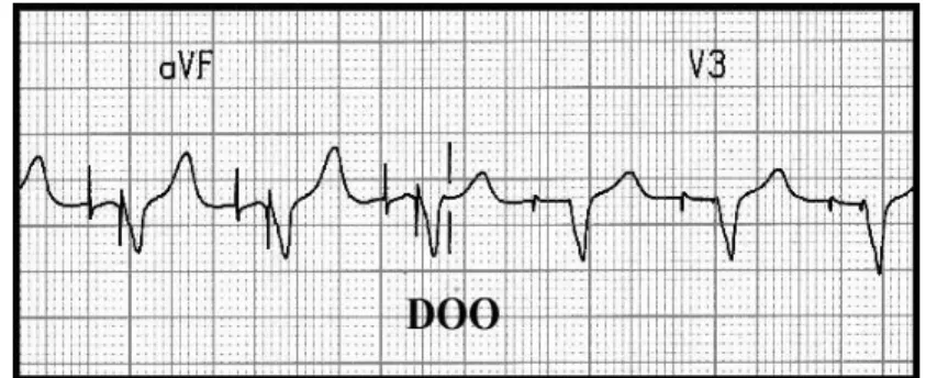
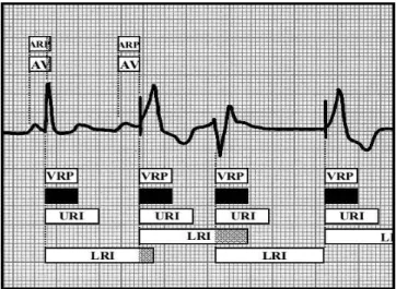
In the double electrode pacemaker system, the pacemaker delivers a pacing stimulus in the atrial and ventricular chambers. In DOO operating mode of double electrode cardiac pacemaker system, the first letter ’D’ represents that the pacemaker paces both atrial and ventricle, second letter ’O’ represents that the pacemaker does not sense the atrial and the ventricle chambers and final letter ’O’ represents that there is no any inhibits or triggers in both chambers (atrail and ventricular). In the block diagram (Fig-5) of heart pacing in DOO operating mode pacemaker will pace both chambers (atrial and ventricular) asynchronously at the constant rate regardless of the underlying rhythm. It does not sense, If the native rhythm is slower than the constant rate then atrial
Fig. 5 Basic block diagram of ECG rhythm strip in DOO Operating Mode In our initial model, we have formalized the functional behaviors of the car-diac pacemaker system , where two new variables P M Actuator A and P M Actuator V are represented ON or OFF states of the pacemaker’s actuators for pacing in the atrial and ventricular chambers. An interval between two paces is defined by a new variable P ace Int that must be between upper rate interval (URI) and lower rate interval (LRI), is represented by an invariant (inv3). The vari-able P ace Int is an interval between two paces of ventricular chamber that is initialized by the system before start the pacing. This interval is equal to atrioventricular(AV) interval plus ventriculoatrial(VA) interval. A variable sp (since pace) represents a current clock counter. A variable last sp represents the last interval (in ms.) between two paces and a safety property in invariant (inv5) states that last interval must be between U RI and LRI. In invariant (inv6) a new variable Atria state is used as boolean type to control the state of the atrial chamber. The invariant (inv7) states that the pacemaker’s actuator of atrial and ventricular chambers are OF F when clock counter sp is less than ven-triculoatrial (VA) interval and atrial state (Atria state) is F ALSE. The next invariant (inv8) represents that the pacemaker’s actuator of both chambers are OF F when clock counter sp is greater than atrioventricular (AV) interval and atrial state (Atria state) is T RU E. The last invariants (inv9 and inv10) state that pacemaker’s actuator of atrial is ON when clock counter sp is equal to ven-triculoatrial (VA) interval P ace Int − F ixedAV and pacemaker’s actuator of ventricular is ON when clock counter sp is equal to the pace interval P ace Int, respectively.
inv1 : P M Actuator A ∈ status inv2 : P M Actuator V ∈ status inv3 : P ace Int ∈ U RI .. LRI inv4 : sp ∈ 1 .. P ace Int
inv5 : last sp ≥ U RI ∧ last sp ≤ LRI inv6 : Atria state ∈ BOOL
inv7 : sp < (P ace Int − F ixedAV ) ∧ Atria state = F ALSE ⇒
P M Actuator V = OF F ∧ P M Actuator A = OF F inv8 : sp > (P ace Int − F ixedAV ) ∧ sp < P ace Int ∧
Atria state = T RU E ⇒
P M Actuator A = OF F ∧ P M Actuator V = OF F inv9 : P M Actuator A = ON
⇒
sp = P ace Int − F ixedAV
inv10 : P M Actuator V = ON ⇒ sp = P ace Int
In the abstract specification of DOO operating mode, there are five events P ace ON A to start pacing in atrial, P ace OF F A to stop pacing in atrial, P ace ON V to start pacing in ventricular, P ace OF F V to stop pacing in ventricular and tic to increment the current clock counter sp under real time constraints.
EVENT Pace ON A WHEN
grd1 : P M Actuator A = OF F grd2 : Atria state = F ALSE grd3 : sp = P ace Int − F ixedAV THEN
act1 : P M Actuator A := ON END
The events P ace ON A and P ace OF F A start and stop the pulse discharg-ing into the atrial chamber. The guards and an action of event (P ace ON A) state that pacemaker’s actuator (P M Actuator A) of atrial is ON when pace-maker’s actuator (P M Actuator A) of atrial is OFF, atrial state (Atria state) is FALSE and clock counter sp is equal to ventriculoatrial (VA) interval (P ace Int− F ixedAV ).
EVENT Pace OFF A WHEN
grd1 : P M Actuator A = ON grd2 : P M Actuator V = OF F grd3 : sp = P ace Int − F ixedAV THEN
act1 : P M Actuator A := OF F act2 : Atria state := T RU E END
The guards and actions of event (P ace OF F A) state that pacemaker’s actu-ator (P M Actuactu-ator A) of atrial chamber is OFF and atrial state (Atria state) is TRUE, when pacemaker’s actuator (P M Actuator A) of atrial is ON, pace-maker’s actuator (P M Actuator V ) of ventricular is OFF and clock counter sp is equal to ventriculoatrial (VA) interval (P ace Int − F ixedAV ).
EVENT Pace ON V WHEN grd1 : P M Actuator V = OF F grd2 : P M Actuator A = OF F grd3 : sp = P ace Int THEN act1 : P M Actuator V := ON act2 : last sp := sp END
The events P ace ON V and P ace OF F V also synchronize start and stop the pulse discharging into the ventricular chamber. The guards and actions of event (P ace ON V ) state that pacemaker’s actuator (P M Actuator V ) of ventricular is ON and clock counter sp assigns to a variable (last sp) when pacemaker’s actuator of both chambers (P M Actuator A, P M Actuator V ) is OFF and and clock counter sp is equal to the pace interval (P ace Int).
EVENT Pace OFF V WHEN grd1 : P M Actuator V = ON grd2 : P M Actuator A = OF F grd3 : Atria state = T RU E grd4 : sp = P ace Int THEN act1 : P M Actuator V := OF F act2 : sp := 1
act3 : Atria state := F ALSE END
The guards and actions of event (P ace OF F V ) state that pacemaker’s ac-tuator (P M Acac-tuator V ) of ventricular is OFF, clock counter sp resets to 1 and atrial state (Atria state) sets into TRUE state when pacemaker’s actuator (P M Actuator V ) of ventricular is ON, pacemaker’s actuator (P M Actuator A) of atrial is OFF, atrial state (Atria state) is TRUE and clock counter sp is equal to the pace interval (P ace Int).
EVENT tic WHEN
grd1 : (sp < (P ace Int − F ixedAV )) ∨
(sp ≥ (P ace Int − F ixedAV ) ∧ sp < P ace Int∧ Atria state = T RU E ∧ P M Actuator V = OF F ∧P M Actuator A = OF F )
THEN
act1 : sp := sp + 1 END
The last event tic of this abstraction progressively increases the current clock counter sp under pre-defined pace interval (P ace Int). The guard of this event controls the pacing stimulus into the heart chambers (atrial and ventricular) and synchronizes ON and OFF states of pacemaker’s actuator of each chamber (atrial and ventricular) under real time constraints. The guards of this event provides the required conditions to increase the current clock counter sp by 1 (ms.).
4.1.2 Abstraction of DVI mode:
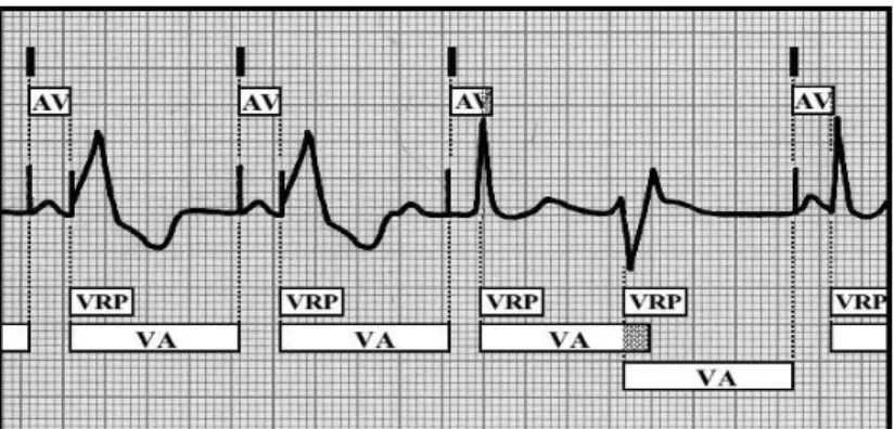
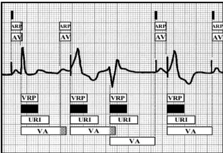
In DVI operating mode of double electrode cardiac pacemaker system, the first letter ’D’ represents that the pacemaker paces both atrial and ventricle, second letter ’V’ represents that the pacemaker senses the ventricle only and final letter ’I’ represents that the ventricular sensing inhibits atrial and ventricular pacing. In the block diagram (Fig-6) of heart pacing in DVI operating mode a ventricu-loatrial (VA) interval follows the timing for each atrioventricular (AV) interval and an atrioventricular (AV) interval follows the timing for each ventriculoatrial (VA) interval, except with an R wave sensed during the ventriculoatrial (VA) interval that starts timing of a new ventriculoatrial (VA) interval.
Fig. 6 Basic block diagram of ECG rhythm strip in DVI Operating Mode In the abstract model of DVI mode, two new variables (P M Actuator A) and (P M Actuator V ) represent the presence (ON) or absence (OFF) of pulse in atrial and ventricular chambers, respectively. The variable (P M Sensor V ) also represents the presence (ON) or absence (OFF) of pacemaker’s sensor in ventricular chamber. An interval between two paces is defined by a new vari-able P ace Int that must be between upper rate interval (URI) and lower rate interval (LRI), is represented by an invariant (inv3). The variable P ace Int is an interval between two paces of ventricular chamber that is initialized by the system before start the pacing. This interval is equal to atrioventricular(AV) interval plus ventriculoatrial(VA) interval. A variable sp (since pace) repre-sents the current clock counter. A variable last sp reprerepre-sents the last interval (in ms.) between two paces and a safety property in invariant (inv6) states that last interval must be greater than or equal to V RP and less than and equal to LRI. In invariant (inv7) a new variable AV Count ST AT E is used as boolean type to control the counting interval of atrioventricular (AV) interval. The variable (AV Count) define as natural number to count the atrioventric-ular (AV) interval. A invariant (inv9) represents that the safety property and states that during the ventricular refractory period (VRP), pacemaker’s actua-tor (P M Actuaactua-tor A, P M Actuaactua-tor V ) of atrial and ventricular chambers are OFF and pacemaker’s sensor (P M Sensor V ) of ventricular chamber is also OFF. The last invariants (inv10 and inv11) state that pacemaker’s actuator of atria is ON when clock counter sp is greater than or equal to ventriculoatrial (VA) interval P ace Int − F ixedAV and pacemaker’s actuator of ventricular is ON when clock counter sp is equal to the pace interval P ace Int, respectively.
inv1 : P M Actuator A ∈ status inv2 : P M Actuator V ∈ status inv3 : P M Sensor V ∈ status inv4 : P ace Int ∈ U RI .. LRI inv5 : sp ∈ 1 .. P ace Int
inv6 : last sp ≥ V RP ∧ last sp ≤ LRI inv7 : AV Count ST AT E ∈ BOOL inv8 : AV Count ∈ N
inv9 : sp < V RP ⇒ P M Actuator A = OF F ∧
P M Actuator V = OF F ∧ P M Sensor V = OF F inv10 : P M Actuator A = ON ⇒
sp ≥ P ace Int − F ixedAV
inv11 : P M Actuator V = ON ⇒ sp = P ace Int
In the abstract specification of DV I operating mode, there are eight events Actuator ON A to start pacing in atria, Actuator OF F A to stop pacing in atria, Actuator ON V to start pacing in ventricular, Actuator OF F V to stop pacing in ventricular, Sensor ON V to star sensing in ventricular, Sensor OF F V to stop sensing in ventricular, tic to increment the current clock counter sp under real time constraints and tic AV to count the atrioventricular (AV) interval.
EVENT Actuator ON V WHEN grd1 : P M Actuator V = OF F grd2 : (sp = P ace Int) grd3 : sp ≥ V RP THEN act1 : P M Actuator V := ON act2 : last sp := sp END
The events Actuator ON V and Actuator OF F V start and stop the pace-maker’s actuator in ventricular chamber and synchronizes ON and OFF states. The guards of event Actuator ON V represent that when pacemaker’s actua-tor (P M Actuaactua-tor V ) of ventricular is OFF, current clock counter sp is equal to pace interval (P ace Int) and greater than or equal to VRP. The actions repre-sent that if all guards are satisfy then the pacemaker’s actuator (P M Actuator V ) of ventricular is ON and clock counter sp assigns to a new variable (last sp).
EVENT Actuator OFF V WHEN grd1 : P M Actuator V = ON grd2 : (sp = P ace Int) grd3 : AV Count ≥ F ixedAV THEN act1 : P M Actuator V := OF F act2 : AV Count := 0
act3 : AV Count ST AT E := F ALSE act4 : P M Sensor V := OF F
act5 : sp := 1
act6 : P M Actuator A := OF F END
The guards of event Actuator OF F V states that pacemaker’s actuator (P M Actuator V ) of ventricular is ON and clock counter sp is equal to pace interval (P ace Int) and atrioventricular (AV) counter (AV Count) is greater than or equal to atrioventricular (AV) interval (F ixedAV ). The actions of this event reset all the required parameters of cardiac pacemaker system. The actions (act1−act6) of this event state that the pacemaker’s actuator (P M Actuator V ) of ventricular sets in OFF state, assigns the value of variable (AV count) as 0, atrioventricular (AV) counter state (AV Count ST AT E) sets in FALSE state, pacemaker’s sensor (P M Sensor V ) of ventricular sets in OFF state, assigns the value of clock counter sp as 1 and sets in OFF state of pacemaker’s actuator (P M Actuator A) of atrial.
EVENT Actuator ON A WHEN
grd1 : P M Sensor V = ON
grd2 : sp ≥ P ace Int − F ixedAV ∧ sp ≥ V RP ∧ sp < P ace Int grd3 : P M Actuator A = OF F grd4 : AV Count ST AT E = F ALSE THEN act1 : P M Actuator A := ON act2 : P M Sensor V := OF F END
The actions (act1, act2) of event (Actuator ON A) state that the pace-maker’s actuator (P M Actuator A) of atria sets in ON state and pacepace-maker’s sensor (P M Sensor V ) of ventricular sets in OFF state when all guards satisfy. The first guard of this event states that pacemaker’s sensor (P M Sensor V ) of ventricular is ON, the next guard (grd2) states that clock counter sp is greater than or equal to ventriculoatrial (VA) interval, VRP and less than pace interval (P ace Int)), the third guard shows that the pacemaker’s actuator
(P M Actuator A) of atrial is OFF and and in last guard states that atrioven-tricular (AV) counter state (AV Count ST AT E) is FALSE.
EVENT Actuator OFF A WHEN
grd1 : P M Actuator A = ON
grd2 : sp ≥ P ace Int − F ixedAV ∧ sp ≥ V RP ∧ sp < P ace Int grd3 : AV Count ST AT E = F ALSE
THEN
act1 : P M Actuator A := OF F act2 : AV Count ST AT E := T RU E END
The actions (act1, act2) of event (Actuator OF F A) state that pacemaker’s actuator (P M Actuator A) of atria is OFF and atrioventricular (AV) counter state (AV Count ST AT E) is TRUE. The guards (grd1 − grd2) of this event state that pacemaker’s actuator (P M Actuator A) of atria is ON, clock counter sp is greater than or equal to ventriculoatrial (VA) interval, VRP and less than pace interval (P ace Int). The last guard shows that atrioventricular (AV) counter state (AV Count ST AT E) is FALSE.
EVENT Sensor ON V WHEN
grd1 : P M Sensor V = OF F grd2 : (sp < P ace Int − F ixedAV )
∨
(sp ≥ P ace Int − F ixedAV ∧ AV Count ST AT E = T RU E) grd3 : sp ≥ V RP
THEN
act1 : P M Sensor V := ON END
The events (Sensor ON V and Sensor OF F V ) is used to control the sens-ing activities from the ventricular chamber. The pacemaker’s sensor (P M Sensor V ) of ventricular chamber synchronizes the ON and OFF states under real time constraints. The guard (grd1) of event (Sensor ON V ) represents that if pace-maker’s sensor (P M Sensor V ) of ventricular is OFF and a guard (grd2) repre-sents that current clock counter sp is less than ventriculoatrial (VA) interval or greater than or equal to ventriculoatrial (VA) interval and atrioventricular (AV)
EVENT Sensor OFF V WHEN grd1 : P M Sensor V = ON grd2 : sp ≥ V RP ∧ sp < P ace Int THEN act1 : P M Sensor V := OF F act2 : AV Count := 0
act3 : AV Count ST AT E := F ALSE act4 : last sp := sp
act5 : sp := 1
act6 : P M Actuator V := OF F act7 : P M Actuator A := OF F END
The event (Sensor OF F V ) is used to set the pacemaker’s sensor (P M Sensor V ) of ventricular is OFF. The guards of this event represent that the pacemaker’s sensor (P M Sensor V ) of ventricular is ON and current clock counter sp is greater than or equal to VRP and less than pace interval (P ace Int). All ac-tions of this event is same as event (Actuator OF F V ) of DOO operating mode, which are already described. Here only extra action (act1) is added to set the pacemaker’s sensor (P M Sensor V ) of ventricular is in OFF state.
EVENT tic WHEN
grd1 : (sp < V RP ∧ P M Sensor V = OF F ) ∨
(sp ≥ V RP ∧ sp < P ace Int ∧ P M Sensor V = ON ∧ AV Count ST AT E = F ALSE)
THEN
act1 : sp := sp + 1 END
The event (tic) of this abstraction progressively increases the current clock counter sp under pre-defined pace interval (P ace Int). The guard (grd1) of this event control the pacing stimulus into the heart chambers (atria and
ventricu-lar), synchronizes ON and OFF states of the pacemaker’s actuator (P M Actuator A, P M Actuator V ) of each chamber (atria and ventricular) and also control the sensing intrinsic
stimulus of ventricular chamber and synchronizes the ON and OFF states of ventricular pacemaker’s sensor (P M Sensor V ) under real time constraints.
EVENT tic AV WHEN
grd1 : AV Count ≤ F ixedAV grd2 : AV Count ST AT E = T RU E
grd3 : sp ≥ P ace Int − F ixedAV ∧ sp < P ace Int THEN
act1 : AV Count := AV Count + 1 act2 : sp := sp + 1
END
The last event (tic AV ) of this abstraction progressively counts the atri-oventricular (AV) interval and also increases the current clock counter sp is represented in actions (act1 and act2) . The guards (grd1 − grd3) of this event states that atrioventricular (AV) counter (AV Count) is less than and equal to atrioventricular (AV) interval (F ixedAV ), atrioventricular (AV) counter state (AV count ST AT E) is in TRUE state and current clock counter sp is within the atrioventricular (AV) interval.
4.1.3 Abstraction of DDI mode:
In DDI operating mode of double electrode pacemaker system, the first letter ’D’ represents that the pacemaker paces both atrial and ventricle, second let-ter ’D’ represents that the pacemaker senses both atrial and ventricle and final letter ’I’ represents two conditional meaning that depends on atrial and ven-tricular sensing; first is that atrial sensing inhibits atrial pacing and does not trigger ventricular pacing and second is that ventricular sensing inhibits ven-tricular and atrial pacing. In the block diagram (Fig-7) of heart pacing in DDI operating mode a new LRI follows the timing of each preceding LRI. The timing of an atrioventricular (AV) interval occurs within this period only following a completed ventriculoatrial (VA) interval (i.e., when no atrial sensing occurs).
In this abstract model, we have formalized a bradycardia operating mode DDI of the double electrode pacemaker. In this operating mode, the pacemaker uses actuators and sensors in both chambers. We have defined two new vari-ables P M Actuator A and P M Actuator V that represent ON or OFF states of pacemaker’s actuators for pacing in the atrial and ventricular chambers. Sim-ilarly next two variables P M Sensor A and P M Sensor V represent ON or OFF states of pacemaker’s sensor for sensing an intrinsic pulse from both the atrial and ventricular chambers. An interval between two paces is defined by a new variable P ace Int that must be between upper rate interval (URI) and lower rate interval (LRI), is represented by an invariant (inv5). A variable sp (since pace) represents the current clock counter. A variable last sp represents the last interval (in ms.) between two paces and a safety property in invari-ant (inv7) states that last interval must be between PVARP and pace interval P ace Int. Another new variable AV Count ST AT E is defined as boolean type to control the atrioventricular (AV) interval state and next variable AV Count is defined as natural number to count the atrioventricular (AV) interval. Ex-tra two new invariants (inv11 and inv12) represent the safety properties. The invariant (inv11) states that when clock counter sp is less than ventricular re-fractory period (VRP) and atrioventricular (AV) counter state is FALSE then the pacemaker’s actuators and sensors of both chambers are OFF. The next invariant (inv12) represents that the pacemaker’s actuator of ventricular is ON when clock counter sp is equal to the pace interval P ace Int.
inv1 : P M Actuator A ∈ status inv2 : P M Actuator V ∈ status inv3 : P M Sensor A ∈ status inv4 : P M Sensor V ∈ status inv5 : P ace Int ∈ U RI .. LRI inv6 : sp ∈ 1 .. P ace Int
inv7 : last sp ≥ P V ARP ∧ last sp ≤ P ace Int inv8 : AV Count ST AT E ∈ BOOL
inv9 : AV Count ∈ N
inv10 : P ace Int − F ixedAV < P ace Int
inv11 : sp < V RP ∧ AV Count ST AT E = F ALSE ⇒
P M Actuator A = OF F ∧ P M Actuator V = OF F ∧ P M Sensor A = OF F ∧ P M Sensor V = OF F
inv12 : P M Actuator V = ON ⇒ sp = P ace Int
In the abstract specification of DDI operating mode, there are ten events Actuator ON A to start pacing in atria, Actuator OF F A to stop pacing in atria, Actuator ON V to start pacing in ventricular, Actuator OF F V to stop pacing in ventricular, Sensor ON V to start sensing in ventricular, Sensor OF F V
to stop sensing in ventricular, Sensor ON A to star sensing in atrial, Sensor OF F A to stop sensing in atrial, tic to increment the current clock counter sp under real time constraints and tic AV to count the atrioventricular (AV) interval.
EVENT Actuator ON V WHEN grd1 : P M Actuator V = OF F grd2 : (sp = P ace Int) grd3 : sp ≥ V RP ∧ sp ≥ P V ARP THEN act1 : P M Actuator V := ON act2 : last sp := sp END
The events Actuator ON V and Actuator OF F V start and stop the pace-maker’s actuator (P M Actuator V ) in ventricular chamber and synchronizes ON and OFF states. The guards of event (Actuator ON V ) represent that when pacemaker’s actuator (P M Actuator V ) of ventricular is OFF, current clock counter sp is equal to pace interval (P ace Int), in next guard current clock counter sp is greater then or equal to ventricular refractory period (VRP) and post ventricular refractory period (PVARP). The actions of this event represent that if all guards are satisfy then the pacemaker’s actuator (P M Actuator V ) of ventricular is ON and current clock counter sp assigns to a variable (last sp).
EVENT Actuator OFF V WHEN
grd1 : P M Actuator V = ON
grd2 : (sp ≥ P ace Int) ∧ sp ≥ V RP ∧ sp ≥ P V ARP grd3 : AV Count ST AT E = T RU E grd4 : P M Sensor A = OF F grd5 : P M Actuator A = OF F THEN act1 : P M Actuator V := OF F act2 : AV Count := 0
act3 : AV Count ST AT E := F ALSE act4 : P M Sensor V := OF F
act5 : sp := 1 END
reset all the parameters of operating mode of the pacemaker system. The actions (act1−act5) of this event state that the pacemaker’s actuator (P M Actuator V ) of ventricular sets OFF, assigns the value of variable (AV count) as 0, atrioven-tricular (AV) counter state (AV Count ST AT E) sets FALSE, the pacemaker’s sensor (P M Sensor V ) of ventricular sets OFF and assigns the value of the current clock counter sp as 1.
EVENT Actuator ON A WHEN
grd1 : P M Sensor V = ON
grd2 : sp ≥ P ace Int − F ixedAV ∧ sp ≥ V RP ∧ sp ≥ P V ARP grd3 : P M Actuator A = OF F grd4 : P M Sensor A = ON THEN act1 : P M Actuator A := ON act2 : P M Sensor V := OF F act3 : P M Sensor A := OF F END
The actions (act1 − act3) of event (Actuator ON A) state that the pace-maker’s actuator (P M Actuator A) of atrial sets ON and the pacepace-maker’s sen-sor (P M Sensen-sor V, P M Sensen-sor A) of ventricular and atrial set OFF when all guards satisfy. The first guard of this event states that the pacemaker’s sen-sor (P M Sensen-sor V ) of ventricular is ON, the next guard (grd2) states that current clock counter sp is greater than or equal to ventriculoatrial (VA) in-terval, VRP and PVARP, the third guard shows that the pacemaker’s actuator (P M Actuator A) of atrial is OFF and and in last guard states that the pace-maker’s sensor (P M Sensor A) of atrial is ON.
EVENT Actuator OFF A WHEN
grd1 : P M Actuator A = ON
grd2 : sp = P ace Int − F ixedAV ∧ sp ≥ V RP ∧ sp ≥ P V ARP grd3 : AV Count ST AT E = F ALSE
THEN
act1 : P M Actuator A := OF F act2 : AV Count ST AT E := T RU E END
The actions (act1, act2) of event (Actuator OF F A) state that the pace-maker’s actuator (P M Actuator A) of atria sets in OFF state and atrioventric-ular (AV) counter state (AV Count ST AT E) sets in TRUE state. The guards (grd1, grd2) of this event state that the pacemaker’s actuator (P M Actuator A) of atria is ON, current clock counter sp is greater than or equal to ventriculoa-trial (VA) interval, VRP and PVARP. In last guard states that atrioventricular (AV) counter states (AV Count ST AT E) is FALSE.
EVENT Sensor ON A WHEN
grd1 : P M Sensor A = OF F
grd2 : sp < P ace Int − F ixedAV ∧ sp ≥ V RP ∧ sp ≥ P V ARP grd3 : P M Sensor V = OF F
THEN
act1 : P M Sensor A := ON END
The events (Sensor ON A and Sensor OF F A) is used to control the sens-ing activities from the atrial chamber. The pacemaker’s sensor (P M Sensor A) of atrial chamber synchronizes ON and OFF states under real time constraints. The guard (grd1) of event (Sensor ON A) represents that if the pacemaker’s sensor (P M Sensor A) of atrial is OFF and next guard (grd2) represents that the current clock counter sp is less than ventriculoatrial (VA) interval and greater than or equal to VRP and PVARP. The last guard (grd3) represents that the pacemaker’s sensor (P M Sensor V ) of ventricular is OFF. If all guards are true then in action part of this event the pacemaker’s sensor (P M Sensor A) of atrial sets ON state.
EVENT Sensor OFF A WHEN
grd1 : P M Sensor A = ON
grd2 : sp < P ace Int − F ixedAV ∧ sp ≥ V RP ∧ sp ≥ P V ARP THEN
act1 : P M Sensor A := OF F act2 : AV Count ST AT E := T RU E END
The event (Sensor OF F A) is used to set the pacemaker’s sensor (P M Sensor A) of atrial in OFF state. The guards of this event represent that the pacemaker’s sensor (P M Sensor A) of atrial is ON and current clock counter sp is less than ventriculoatrial (VA) interval and greater than or equal to VRP and PVARP. In actions of this event state that the pacemaker’s sensor (P M Sensor A) of atrial sets OFF and atrioventricular (AV) counter state sets TRUE.
EVENT Sensor ON V WHEN
grd1 : P M Sensor V = OF F
grd2 : (sp ≥ V RP ∧ sp < P ace Int − F ixedAV ∧ P M Sensor A = ON ) ∨
(sp ≥ P ace Int − F ixedAV ∧ AV Count ST AT E = T RU E) grd3 : P M Actuator A = OF F
THEN
act1 : P M Sensor V := ON END
The events (Sensor ON V and Sensor OF F V ) is used to control the sens-ing activities from the ventricular chamber. The pacemaker’s sensor (P M Sensor V ) of ventricular chamber synchronizes ON and OFF states under real time con-straints. The guard (grd1) of event (Sensor ON V ) represents that if the pace-maker’s sensor (P M Sensor V ) of ventricular is OFF and in next guard (grd2) shows that current clock counter sp is greater than or equal to VRP, less than ventriculoatrial (VA) interval and the pacemaker’s sensor (P M Sensor A) of atrial is ON, or greater than or equal to ventriculoatrial (VA) interval and atri-oventricular (AV) counter state (AV Count ST AT E) is TRUE. The last guard (grd3) states that the pacemaker’s actuator (P M Actuator A) of atrial is OFF. If all guards are true then in action part of this event, the pacemaker’s sensor (P M Sensor V ) of ventricular sets in ON state.
EVENT Sensor OFF V WHEN
grd1 : P M Sensor V = ON grd2 : sp ≥ V RP ∧ sp ≥ P V ARP grd3 : (sp < P ace Int − F ixedAV )
∨
(sp ≥ P ace Int − F ixedAV ∧ sp < P ace Int) grd4: P M Actuator V = OF F
grd5: P M Actuator A = OF F THEN
act1 : P M Sensor V := OF F act2 : AV Count := 0
act3 : AV Count ST AT E := F ALSE act4 : last sp := sp
act5 : sp := 1
act6 : P M Sensor A := OF F END
The event (Sensor OF F V ) is used to set the pacemaker’s sensor (P M Sensor V ) of ventricular in OFF state. The guards (grd1, grd2) of this event represent that the pacemaker’s sensor (P M Sensor V ) of ventricular is ON and current clock
counter sp is greater than or equal to VRP and PVARP. The next guard (grd3) represents that the current clock counter sp is less than ventriculoatrial (VA) interval or greater than or equal to ventriculoatrial (VA) interval and less than pace interval (P ace Int). The last two guards (grd4, grd5) state that the pace-maker’s actuator (P M Actuator V, P M Actuator A) of ventricular and atrial are OFF. The actions (act1 − act6) of this event state that the pacemaker’s sensor (P M Sensor V ) of ventricular sets OFF, assigns the value of variable (AV count) as 0, atrioventricular (AV) counter state (AV Count ST AT E) sets FALSE, assigns the value of the current clock counter sp to new variable (last sp), assigns the value of clock counter sp as 1 and sets OFF state of the pacemaker’s actuator (P M Actuator A) of the atrial chamber.
EVENT tic WHEN
grd1 : (sp < V RP ) ∨
(sp ≥ V RP ∧ sp < P ace Int − F ixedAV ∧ P M Sensor V = ON THEN
act1 : sp := sp + 1 END
The event tic of this abstraction progressively increases the current clock counter sp under pre-defined pace interval (P ace Int). The guards of this event control the pacing stimulus into the heart chambers (atria and ventricular),
syn-chronize ON and OFF states of the pacemaker’s actuator (P M Actuator A, P M Actuator V ) of each chamber (atria and ventricular) and also control the sensing intrinsic
stimulus from atrial and ventricular chambers and synchronize ON and OFF states of the pacemaker’s sensor (P M Sensor A, P M Sensor V ) in both cham-bers under real time constraints.
EVENT tic AV WHEN
grd1 : AV Count ≤ F ixedAV grd2 : AV Count ST AT E = T RU E
grd3 : sp ≥ P ace Int − F ixedAV ∧ sp < P ace Int THEN
act1 : AV Count := AV Count + 1 act2 : sp := sp + 1
TRUE and the current clock counter sp is within the atrioventricular (AV) interval.
4.1.4 Abstraction of VDD mode:
In VDD operating mode of the double electrode pacemaker system, the first letter ’V’ represents that the pacemaker paces ventricle only, second letter ’D’ represents that the pacemaker senses both atrial and ventricle and final letter ’D’ represents two conditional meaning that depends on atrial and ventricular sensing; first is that atrial sensing triggers ventricular pacing and second is that ventricular sensing inhibits ventricular pacing. In the block diagram (Fig-8) of heart pacing in VDD operating mode a new LRI follows the timing of each preceding LRI. When a sensed P wave occurs an atrioventricular (AV) interval is triggered within.
Fig. 8 Basic block diagram of ECG rhythm strip in VDD Operating Mode In this abstract model, we have formalized a bradycardia operating mode VDD of the double electrode pacemaker. In this operating mode, the pace-maker uses actuators and sensors in both chambers. We have defined a new variable P M Actuator V that represents ON or OFF states of pacemaker’s ac-tuators for pacing in the ventricular chamber. Next two variables P M Sensor A and P M Sensor V represent the ON or OFF states of pacemaker’s sensor for sensing an intrinsic pulse from both the atrial and ventricular chambers. An interval between two paces is defined by a new variable P ace Int that must be between upper rate interval (URI) and lower rate interval (LRI), is repre-sented by an invariant (inv4). A variable sp (since pace) represents the current clock counter. A variable last sp represents the last interval (in ms.) between two paces and a safety property in invariant (inv6) states that last interval must be between PVARP and pace interval P ace Int. Another new variable AV Count ST AT E in invariant (inv7) is defined as boolean type to control the atrioventricular (AV) interval state and next variable AV Count is defined as
natural number to count the atrioventricular (AV) interval by invariant (inv8). Here new invariant (inv10) represents the safety property and states that when clock counter sp is less then ventricular refractory period (VRP) and atrioven-tricular (AV) counter state (AV Count ST AT E) is T RU E, the pacemaker’s actuator (P M Actuator V ) of ventricular is OF F and pacemaker’s sensors of both chambers are OFF. The next invariant (inv11) represents that pacemaker’s actuator (P M Actuator V ) of ventricular is ON when clock counter sp is either equal to the pace interval P ace Int or clock counter sp less than pace interval P ace Int and atrioventricular (AV) counter AV Count is greater then blanking period V Blank and greater than or equal to the atrioventricular (AV) period F ixedAV .
inv1 : P M Actuator V ∈ status inv2 : P M Sensor A ∈ status inv3 : P M Sensor V ∈ status inv4 : P ace Int ∈ U RI .. LRI inv5 : sp ∈ 1 .. P ace Int
inv6 : last sp ≥ P V ARP ∧ last sp ≤ P ace Int inv7 : AV Count ST AT E ∈ BOOL
inv8 : AV Count ∈ N
inv9 : P ace Int − F ixedAV < P ace Int
inv10 : sp < V RP ∧ AV Count ST AT E = F ALSE ⇒ P M Actuator V = OF F ∧ P M Sensor A = OF F ∧ P M Sensor V = OF F inv11 : P M Actuator V = ON ⇒ (sp = P ace Int ∨ (sp < P ace Int∧ AV Count > V Blank ∧ AV Count ≥ F ixedAV ))
In the abstract specification of V DD operating mode, there are eight events Actuator ON V to start pacing in ventricular, Actuator OF F V to stop pacing in ventricular, Sensor ON V to star sensing in ventricular, Sensor OF F V to stop sensing in ventricular, Sensor ON A to star sensing in atrial, Sensor OF F A to stop sensing in atrial, tic to increment the current clock counter under real time constraints and tic AV to count the atrioventricular (AV) interval.
EVENT Actuator ON V WHEN
grd1 : P M Actuator V = OF F grd2 : (sp = P ace Int)
∨
(sp < P ace Int ∧ AV Count > V Blank ∧ AV Count ≥ F ixedAV ) grd3 : sp ≥ V RP ∧ sp ≥ P V ARP
THEN
act1 : P M Actuator V := ON act2 : last sp := sp
END
The events Actuator ON V and Actuator OF F V start and stop the pace-maker’s actuator (P M Actuator V ) in ventricular chamber and synchronizes ON and OFF states. The guard (grd1) of event Actuator ON V represents that when the pacemaker’s actuator (P M Actuator V ) of ventricular is OFF and in guard (grd2) the current clock counter sp is equal to pace interval (P ace Int) or less than pace interval P ace Int and atrioventricular (AV) counter (AV Count) is greater than blanking period (V Blank) and greater than or equal to atri-oventricular (AV) interval (F ixedAV ). In the last guard, the current clock counter sp is greater than or equal to ventricular refractory period (VRP) and post ventricular refractory period (PVARP). The actions of this event represent that if all guards are satisfy then the pacemaker’s actuator (P M Actuator V ) of ventricular is ON and clock counter sp assigns to a new variable (last sp).
EVENT Actuator OFF V WHEN
grd1 : P M Actuator V = ON grd2 : (sp = P ace Int)
∨
(sp ≥ V RP ∧ sp < P ace Int ∧ AV Count > V Blank∧ AV Count ≥ F ixedAV ∧ AV Count ST AT E = T RU E) grd2 : (sp ≥ P V ARP )
THEN
act1 : P M Actuator V := OF F act2 : AV Count := 0
act3 : AV Count ST AT E := F ALSE act4 : P M Sensor V := OF F
act5 : P M Sensor A := OF F act6 : last sp := sp
act7 : sp := 1 END
The guards of event Actuator OF F V states that the pacemaker’s actu-ator (P M Actuactu-ator V ) of ventricular is ON and current clock counter sp is
equal to the pace interval P ace Int or greater than or equal to VRP, less than pace interval (P ace Int), atrioventricular (AV) counter (AV Count) is greater than blanking period (V Blank), atrioventricular (AV) counter (AV Count) is greater than or equal to the atrioventricular (AV)interval (F ixedAV ) and atri-oventricular (AV) counter state (AV Count State) is TRUE. The last guard states that current clock counter sp is greater than or equal to PVARP. The actions of this event reset the all parameters of the pacemaker for beginning the pacing cycle. In action (act1) sets OFF state of the pacemaker’s actua-tor (P M Actuaactua-tor V ) of ventricular, in the second action reassign the value of variable (AV count) as 0, in next action (act3) sets FALSE state to the AV counter state AV Count ST AT E, sets OFF state to the pacemaker’s sensor (P M Sensor V, P M Sensor A) of both chambers in actions (act4, act5), in ac-tion (act6) assigns the value of the current clock counter sp to new variable last sp and finally in action (act7) assigns the value of the current clock counter sp as 1.
EVENT Sensor ON A WHEN
grd1 : P M Sensor A = OF F
grd2 : sp < P ace Int − F ixedAV ∧ sp ≥ V RP ∧ sp ≥ P V ARP grd3 : P M Sensor V = OF F
THEN
act1 : P M Sensor A := ON END
The events (Sensor ON A and Sensor OF F A) is used to control the sens-ing activities from the atrial chamber. The pacemaker’s sensor (P M Sensor A) of atrial chamber synchronizes ON and OFF states under real time constraints. The guard (grd1) of event (Sensor ON A) represents that if the pacemaker’s sensor (P M Sensor A) of atrial is OFF and guard (grd2) represents that the current clock counter sp is less than ventriculoatrial (VA) interval and greater than or equal to VRP and PVARP. The last guard (grd3) represents that the pacemaker’s sensor (P M Sensor V ) of ventricular is OFF. If all guards are true then in action part of this event then the pacemaker’s sensor (P M Sensor A) of atrial sets in ON state.
EVENT Sensor OFF A WHEN
The event (Sensor OF F A) is used to set the pacemaker’s sensor (P M Sensor A) of atrial in OFF state. The guards of this event show that the the pace-maker’s sensor (P M Sensor A) of atrial is ON and the current clock counter sp is less than ventriculoatrial (VA) interval and greater than or equal to VRP and PVARP. In actions of this event state that the pacemaker’s sensor (P M Sensor A) of atrial sets in OFF state and atrioventricular (AV) counter state (AV Count ST AT E) sets in TRUE state.
EVENT Sensor ON V WHEN
grd1 : P M Sensor V = OF F
grd2 : (sp ≥ V RP ∧ sp < P ace Int − F ixedAV ∧ P M Sensor A = ON ) ∨
(sp ≥ P ace Int − F ixedAV ∧ AV Count ST AT E = T RU E) THEN
act1 : P M Sensor V := ON END
The events (Sensor ON V and Sensor OF F V ) is used to control the sens-ing activities from the ventricular chamber. The pacemaker’s sensor (P M Sensor V ) of ventricular chamber synchronizes ON and OFF states under real time con-straints. The guard (grd1) of event (Sensor ON V ) represents that if the pacemaker’s sensor (P M Sensor V ) of ventricular is OFF and in next guard (grd2) represents that the current clock counter sp is greater than or equal to VRP, less than ventriculoatrial (VA) interval and the pacemaker’s sensors (P M Sensor A) of atrial is ON or current clock counter sp is greater than or equal to ventriculoatrial (VA) interval and atrioventricular (AV) counter state (AV Count ST AT E) is in TRUE state. If all guards are true then in action part of this event, the pacemaker’s sensor (P M Sensor V ) of ventricular sets in ON state.
EVENT Sensor OFF V WHEN
grd1 : P M Sensor V = ON grd2 : sp ≥ V RP ∧ sp ≥ P V ARP grd3 : (sp < P ace Int − F ixedAV )
∨
(sp ≥ P ace Int − F ixedAV ∧ sp < P ace Int) grd4: P M Actuator V = OF F
THEN
act1 : P M Sensor V := OF F act2 : AV Count := 0
act3 : AV Count ST AT E := F ALSE act4 : last sp := sp
act5 : sp := 1
act6 : P M Sensor A := OF F END
The event (Sensor OF F V ) is used to set the pacemaker’s sensor (P M Sensor V ) of ventricular in OFF state. The guard (grd1) of this event represents that the pacemaker’s sensor (P M Sensor V ) of ventricular is ON and the current clock counter sp is greater than or equal to VRP and PVARP interval. The next guard (grd3) represents that the current clock counter sp is less than ventriculoatrial (VA) interval or greater than or equal to ventriculoatrial (VA) interval and less than automatic pace interval (P ace Int). The last guard (grd4) state that the pacemaker’s actuator (P M Actuator V ) of ventricular is OFF. All actions of this event is same as event (Sensor OF F V ) of DDI operating mode which are already described in actions part of this event (Sensor OF F V ) .
EVENT tic WHEN
grd1 : (sp < V RP ) ∨
(sp ≥ V RP ∧ sp < P ace Int ∧ P M Sensor V = ON ∧ P M Sensor A = ON
THEN
act1 : sp := sp + 1 END
sensor (P M Sensor A, P M Sensor V ) in both chambers under real time con-straints. EVENT tic AV WHEN grd1 : AV Count < F ixedAV grd2 : AV Count ST AT E = T RU E
grd3 : (sp ≥ V RP ∧ sp ≥ P V ARP ∧ sp < P ace Int − F ixedAV ) ∨
(sp ≥ P ace Int − F ixedAV ∧ sp < P ace Int) THEN
act1 : AV Count := AV Count + 1 act2 : sp := sp + 1
END
The last event (tic AV ) of this abstraction progressively counts the atri-oventricular (AV) interval and also increases the current clock counter sp is represented in actions (act1 and act2) . The guards of this event states that atrioventricular (AV) counter (AV Count) is less than atrioventricular (AV) in-terval (F ixedAV ), atrioventricular (AV) state (AV count ST AT E) is in TRUE state and the current clock counter sp is within the ventriculoatrial (VA) in-terval (P ace Int − F ixedAV ) and greater than or equal to VRP and PVARP interval or clock counter sp is greater than or equal to atrioventricular (AV) interval and less than pace interval (P ace Int).
4.1.5 Abstraction of DDD mode:
In DDD operating mode of double electrode pacemaker system, the first letter ’D’ represents that the pacemaker paces in both atrial and ventricle chambers, second letter ’D’ represents that the pacemaker senses intrinsic activities from both atrial and ventricle chambers and final letter ’D’ represents two conditional meaning that depends on atrial and ventricular sensing; first is that atrial sens-ing inhibits atrial pacsens-ing and triggers ventricular pacsens-ing and second is that ventricular sensing inhibits ventricular and atrial pacing. In the block diagram (Fig-9) of heart pacing in DDD operating mode a ventriculoatrial (VA) interval follows the timing for each atrioventricular (AV) interval and an atrioventricular (AV) interval follows the timing for each ventriculoatrial (VA) interval, except with a ’P’ wave or an ’R’ wave (PVC) that starts timing of a new ventriculoatrial (VA) interval.
![Fig. 2 Heart or Natural Pacemaker [1]](https://thumb-eu.123doks.com/thumbv2/123doknet/14234836.486034/6.918.341.573.188.387/fig-heart-or-natural-pacemaker.webp)