HAL Id: hal-01917338
https://hal.archives-ouvertes.fr/hal-01917338
Submitted on 9 Nov 2018
HAL is a multi-disciplinary open access
archive for the deposit and dissemination of
sci-entific research documents, whether they are
pub-lished or not. The documents may come from
teaching and research institutions in France or
abroad, or from public or private research centers.
L’archive ouverte pluridisciplinaire HAL, est
destinée au dépôt et à la diffusion de documents
scientifiques de niveau recherche, publiés ou non,
émanant des établissements d’enseignement et de
recherche français ou étrangers, des laboratoires
publics ou privés.
A mathematical modeling of catalytic milli-fixed bed
reactor for Fischer–Tropsch synthesis: Influence of tube
diameter on Fischer Tropsch selectivity and thermal
behavior
Giovanni Chabot, Richard Guilet, Patrick Cognet, Christophe Gourdon
To cite this version:
Giovanni Chabot, Richard Guilet, Patrick Cognet, Christophe Gourdon. A mathematical modeling of
catalytic milli-fixed bed reactor for Fischer–Tropsch synthesis: Influence of tube diameter on Fischer
Tropsch selectivity and thermal behavior. Chemical Engineering Science, Elsevier, 2015, 127, pp.72-83.
�10.1016/j.ces.2015.01.015�. �hal-01917338�
OATAO is an open access repository that collects the work of Toulouse
researchers and makes it freely available over the web where possible
Any correspondence concerning this service should be sent
to the repository administrator:
tech-oatao@listes-diff.inp-toulouse.fr
This is an author’s version published in:
http://oatao.univ-toulouse.fr/20596
To cite this version:
Chabot, Giovanni and Guilet, Richard and Cognet, Patrick
and Gourdon, Christophe A mathematical modeling of
catalytic milli-fixed bed reactor for Fischer–Tropsch synthesis:
Influence of tube diameter on Fischer Tropsch selectivity and
thermal behavior. (2015) Chemical Engineering Science, 127.
72-83. ISSN 0009-2509
Official URL:
https://doi.org/10.1016/j.ces.2015.01.015
A mathematical modeling of catalytic milli-fixed bed reactor
for Fischer
–Tropsch synthesis: Influence of tube diameter
on Fischer Tropsch selectivity and thermal behavior
Giovanni Chabot
a, Richard Guilet
b,n, Patrick Cognet
a, Christophe Gourdon
aaUniversité de Toulouse, INPT, ENSIACET, Laboratoire de Génie Chimique (LGC UMR 5503), 4 Allée Emile Monso, F-31432 Toulouse, France bUniversité de Toulouse, UPS, Laboratoire de Génie Chimique (LGC UMR 5503), 4 Allée Emile Monso, F-31432 Toulouse, France
H I G H L I G H T S
!A two-dimensional pseudo-homogeneous model in packed bed reactors was built. !Influence of tube reactor diameter for Fischer–Tropsch synthesis was investigated. !Increasing tube diameter leads to hot spot within the reactor.
!Liquid hydrocarbons selectivity decreases if isothermal behavior is not fulfilled. !High productivities in liquid hydrocarbons are obtained at millimeter scale.
Keywords:
Fischer–Tropsch synthesis Fixed bed reactor Milli-reactor Intensification Reactor modeling COMSOL multiphysics
a b s t r a c t
A two-dimensional pseudo-homogeneous model has been developed to investigate the influence of tube size on the thermal behavior and performance of packed fixed bed reactor for the low temperature Fischer– Tropsch (FT) synthesis over alumina supported cobalt. Velocity, temperature and composition fields are determined by solving the fundamental transport equations in porous media. Special attention was paid to the variation of transport properties with temperature and composition of the gas mixture. High dependency of the thermal behavior on the thermal conductivity of the gas mixture is highlighted, whereas viscosity and heat capacity of gas mixture have very little influence. Moreover for the considered catalyst, simulation results have displayed high heat removal for the millimetric scale with a tube inner diameter below 2.75 mm for an extended range of weight hourly space velocity (20–600 gsyngasmin" 1kgcat:" 1, T¼493 K and P¼20 bar). With a
millimetric reactor, high CO conversion ðXCO490%Þ is obtained for values of space velocity between 30 and 120 gsyngasmin" 1kgcat:" 1. For higher diameter tube than 3.11 mm, thermal runaway occurs and even worse, no
convergence achieved due to the very low heat transfer global coefficient and the weak surface/volume ratio, leading to a significant decrease of liquid fuels selectivity and an increase of light hydrocarbon (C1to C4)
selectivity up to 14%. To conclude, results from scale-up study with the millimetric scale are outstanding, more than 2900 kg h" 1
m" 3
cat:of C5 þcould be produce after numbering-up 3033 tubes of 10 centimeters in
length whereas conventional units (multitubular fixed bed reactors or slurry phase reactors) do not exceed 400 kg h" 1m" 3
cat:.
1. Introduction
Over the last few years, a major concern has arisen regarding the decreasing global oil reserves and the associated increasing crude oil price both driven by a strong world demand and by political
instabilities in oil producing regions. Thus, there is nowadays a strong need of alternative sources to supply the world demand for liquid fuels. For several years, first generation biofuels have been produced from the fermentation of sugars or starches to provide bioethanol for gasoline engine or else from the transesterification of veget-able oil to produce biodiesel. However this alternative to fossil fuels has become very controversial and is not indeed devoid of major drawbacks involving a new demand for lands that had been previously devoted to agricultural production and feeding people.
n
Corresponding author. Tel.: þ33 5 34 32 37 18. E-mail address:richard.guilet@iut-tlse3.fr(R. Guilet).
Nevertheless other agricultural feedstock like woodchips and residual of non-food parts of cereal crop, can be valorized and be integrated in a second-generation Biomass to Liquid process (BTL process) to synthesize liquid biofuels via the Fischer–Tropsch synthesis (FTS). This old process, which was developed in the 1920s, kindles a renewal of interest for providing a method to produce liquid hydrocarbons from synthesis gas, the so-called syngas, which is a mixture of CO and H2.
Historically the syngas was obtained from the gasification of coal (CTL process), but nowadays most of syngas is produced from the steam reforming or the partial oxidation of natural gas (GTL process). Moreover for a few years the gasification of biomass (BTL process) has been developed as a sustainable route. The formers CTL and GTL processes are based on fossil resources whereas the latter technology BTL appears to be the most environmentally friendly technology owing to the great abundance of second-generation feedstocks which do not compete with the production of food crop.
More generally, the conversion of syngas via FT synthesis provides a wide product spectrum consisting of methane and a complex multi-component mixture predominantly of linear hydro-carbons (n-alkanes, n-alkenes) and oxygenates. Formation of paraf-finic and oleparaf-finic compounds are respectively illustrated by the chemical equations (Eqs. (1) and (2)) whereas carbon dioxide is produced by the equilibrium reaction Water–Gas-Shift (Eq. (3)). Actually, the reaction mechanism featuring the chain growth follows a polymerization-like scheme based on sequential additions of the monomer CH2. The product range can be described by
Anderson–Schultz–Flory (ASF) distribution, characterized by the chain growth probability parameter
α
which can be considered as independent on the chain length n (Sadeqzadeh et al., 2012): nCOþ ð2nþ 1ÞH2-CnH2n þ 2þ nH2O ð1ÞnCOþ ð2nÞH2-CnH2nþ nH2O ð2Þ
COþH2O⇌CO2þ H2 ð3Þ
2. Background and objectives 2.1. Background
FT synthesis is known for its highly exothermicity ð
Δ
HRÞ ¼" 165 kJ molCO" 1Þ, therefore one of the most important concerns for the development of commercial FT reactors is their necessary heat removal capability that has a major impact on the products selectivity: a temperature increase has the effect of rising methane production as well as results in catalyst deactivation associated to sintering and coking. Four main types of commercial FT reactors are commonly implemented in industrial processes: the fluidized-bed reactor, the multitubular fixed-bed reactor (MFBR), the slurry phase reactor (SPR) and the circulating fluidized-bed reactor. Two operating processes have been developed: the high-temperature FT processes
(573–623 K, HTFT) and the low temperature FT processes (473–523 K, LTFT). HTFT based on iron catalysts yields essentially C1–C15
hydro-carbons in circulating fluidized-bed reactors while LTFT processes lead mainly to linear long chain hydrocarbons (waxes and paraffins). Our study only deals with the LTFT processes for which two main technologies of reactor exist: the slurry-phase reactor and the multi-tubular fixed-bed reactor.Table 1, not intended to be exhaustive, gives the main advantages and drawbacks for both of them.
Although several drawbacks are identified, MFBR are widely used in FT process. These reactors are indeed capable of being easily scaled-up when going from a single tube to multitubular reactor to the extent that a good inlet distribution can be ensured. Moreover, many preliminary studies are carried out in packed-bed reactors at lab-scale such as catalysts developments, kinetic mea-surements and deactivation studies. Nevertheless, within years of development and improvement, some of these drawbacks have been reduced especially those regarding heat removal concerns. However, one of the main limitations of MFBR lies in high pressure drops that can arise when decreasing the catalyst particles dia-meter. No such limitation occurs in slurry phase reactors allowing consequently the use of particles as small as possible and higher effectiveness factors of the catalyst. Actually, particles diameters range from about 100
μ
m when using a slurry reactor to about the millimeter for a MFBR. The use of smaller catalyst pellets in MFBR can obviously increase the effectiveness factor by reducing the diffusion limitations but the catalyst activity rises thereby and heat removal might be difficult to process using conventional reactors. Alternatively, the catalyst and/or the inlet reactor feed need to be highly diluted to prevent hot spot formation. On the other hand, process intensification that has emerged for the recent years has demonstrated the ability of new heat-exchanger reactors to operate in a new way with enhanced mass and heat transfers mainly due to a large surface to volume ratio. Actually, channel size mostly leads to laminar flow but the reduction of the diameter to millimeter allows avoiding unexpected transfer limitations. Milli-structured reactors allow for a strong increase of heat transport in radial direction and thus isothermal operation, even for highly exothermic reactions, becomes feasible.Thus, recent works have shown that microchannel reactors and milli-fixed bed reactors were an alternative to conventional fixed-bed reactors, i.e. based on centimeter-scale tubes assembly, to operate FT synthesis. By greatly reducing the size and cost of chemical processing hardware, micro and/or milli-channel process technology holds the potential to enable cost effective production of synthetic fuels in smaller scale facilities. In particular, Velocys has developed a microchannel FT reactor. They announced a production from 28 to 40 barrels per day/full reactor with productivity several times higher than conventional process developed by Sasol or Shell.
Cao et al. (2009) have performed experiments in microchannel reactor system with active cooling to maintain isothermal condi-tions in the catalyst bed. The catalytic portion of the reactor is a microchannel slot sandwiched within two separated oil-heating channels. Chambrey et al. (2011) experimentally compared with
Table 1
Comparison between two commercial FT reactors operating the LTFT process (Dry, 2002).
Advantages Drawbacks
MFBR Turbulent flow is ensured by the short distance between catalyst particles and especially by a high velocity of syngas
High-pressure operation and pressure drop causes high gas compression costs
Separation of liquid products from the catalyst phase is easy to process Replacement of the catalyst requires special care
Plug flow conditions are obtained Catalyst sintering can occur due to high operating temperature
When tubes diameter increases, difficult heat removal and no temperature control can lead to hot-spot formation
SPR Slurry phase is well mixed and tends to isothermal conditions Separation of the wax product from the catalyst is difficult High productivity per mass of catalyst (lower charge than for fixed bed reactor) Well mixed reactor behavior tends to decrease the reactions rates
centimetric and millimetric tubular fixed bed reactors under exactly the same operating conditions (CoPt/Al2O3, 220 1C, 20 bar, H2/CO2).
The authors found an increase from 40 to 60% of conversion indicating that the millimetric fixed bed represented a real gain in term of productivity. The reasons of this improvement are unclear: absence of internal temperature gradient, role of the hydrody-namics of both phases as the expected increase of the superficial velocity for smaller reactor diameter. Many other works report and highlight the interest in producing biofuels in intensified reactors.
Knochen et al. (2010)concluded that a milli-structured fixed-bed reactor was an interesting option for small FTS plants since high volume specific productivity can be obtained at acceptable pressure drops. Moreover, Myrstad et al. (2009) showed the ability of structured reactor to operate FT synthesis with high active catalyst at severe conditions without thermal runaway and subsequent high deactivation of the catalyst. Catalyst grafted on stainless steel walls of a microchannel reactor substrate demonstrated high activity under FT reaction. Activity and selectivity were higher under microchannel conditions than in a classical fixed-bed catalytic reactor (Guillou, 2005). In addition to these experimental studies, some works based on numerical simulations (Atwood and Bennett, 1979; Bub et al., 1980; Jess et al., 1999; Wang et al., 2003; Wu et al., 2010) have concluded that FT synthesis carried out in intensified systems is enhanced considerably due to mass and heat transfer increase. Actually a few mathematical modeling studies on fixed bed FT reactors have been reported in literature. An oversimplified 1-D heterogeneous plug flow model was used to describe a centimetric reactor as early as 1979 (Atwood and Bennett, 1979). Although intraparticle diffusion was considered with the assumption that the kinetics was first order in CO, no model of product distribution was developed. Now, several FT reactors 1-D or 2-D models have been developed based on various assumptions. A comparison between one-dimensional and two-dimensional model suggested that the 2-D model leads to more accurate prediction when thermal runaway occurs (Jess and Kern, 2009). Some authors (Jess and Kern, 2009, 2012; Lee and Chung, 2012) reported that hot spots and radial temperature gradients occurred using a 4.6-centimeter tube dia-meter with particle diadia-meter close to 3 mm. Although numerous parameters were studied in these works such as inlet temperature, cooling temperature, particle diameter or molar ratio H2/CO, no
parametric study concerning the tube diameter has been performed in the millimetric range.
2.2. Objectives
The main objective of this work is to study how the diameter affects the reactor behavior in terms of conversion, selectivities, temperature gradients and production of the various hydrocarbon fractions. The model system is based on double-shell packed-bed reactor with various diameter. A computational 2-D model coupled with mass and heat transport and hydrodynamic equations is used to predict how the FT reaction occurs. The hot-spot formation and pressure drop within the reactor were investigated according to the diameter with regards to parameters such as weight hourly space velocity (WHSV) and shell cooling temperature. Finally, the poten-tial of milli-structured is evaluated in a short scale-up study.
3. Kinetics of Fischer–Tropsch synthesis
The major challenge in kinetic modeling is to describe the FT reaction with regards to the complexity of the reactions mechan-isms and the large number of species involved. Some models are based only on CO and/or H2conversion and do not consider the
selectivity although those are both greatly influenced by tempera-ture gradients. According toLee and Chung (2012), three different
approaches to describe FT kinetics arise: (1) kinetic model based on mechanistic proposal consisting in a sequence of elementary reactions involving adsorbents and/or intermediates; (2) empirical expressions of general power-law kinetics; and (3) semi-empirical kinetics based on FT mechanisms. The third approach is generally based on Langmuir–Hinselwood–Hougen–Watson (LHHW) model equations. On the basis of carbide or enolic mechanisms, Sarup and Wojciechowski (1989)defined with regards to LHHW equa-tions a kinetic model for the FT synthesis rate regarding CO and H2,
consumption which the general form is given by rFT¼ kFTPaCOPbH2 1þP ikiPcCOi P di H2 " #2 ð4Þ
A review of kinetics equation for iron-based catalyst is given by
Huff and Satterfield (1984) and Zimmerman and Bukur (1990). Many investigators also worked on kinetics expression for cobalt-based catalyst (Anderson et al., 1951; Outi et al., 1981; Sarup and Wojciechowski, 1989; Yates and Satterfield, 1991). The latter simplified the equations of Sarup and Wojciechowski down to only two parameters: the reaction constant kFT and the adsorption
constant k1:
rFT¼
kFTCCOCH2
1þk1CCO
ð Þ2 ð5Þ
Regarding the catalyst, iron and cobalt on various oxide supports have been widely used for FT synthesis. A short description of their respective advantages and drawbacks is given by Khodakov et al. (2007). Although cobalt catalysts are more expensive than iron ones, cobalt catalysts exhibit a greater resistance to attrition, a higher productivity and a lower sensitivity to water. Moreover, a product distribution model has been developed byPhilippe et al. (2009)at high temperature over cobalt-based catalyst. Only paraf-fin production according to Eq.(1)is considered. Indeed, for sake of simplicity in the modeling, olefins (Eq.(2)and oxygenates produc-tions are not examined and the formation of carbon dioxide by Water Gas Shift reaction (Eq.(3)) is neglected, cause of the weak activity of cobalt based catalyst for the WGS reaction (Newsome, 1980). All kinetic parameters and adsorption constant k1 follow
Arrhenius law and activation energies are taken fromPhilippe et al. (2009). The monoxide carbon consumption rate is
rCO¼ " rFT ð6Þ with rFT¼ a ' exp " Ea RT $ % ' CCO' CH2 1þb ' exp "
Δ
Hb RT $ % ' CCO $ %2 ð7ÞFrom the stoichiometry of Eq.(1), water formation rate becomes rH2O¼ " rCO¼ þ rFT ð8Þ
Production rates of methane rC1and ethane rC2are written following
two specifics laws with two temperature dependent parameters via Arrhenius law: rC1¼ d ' exp " Ed RT $ % ' rFT ð9Þ rC2¼ e ' exp " Ee RT $ % ' rFT ð10Þ
For higher linear hydrocarbons ðn42Þ each hydrocarbon production rate is determined using a recursive kinetic model based on Anderson–Schultz–Flory theory. A constant chain growth probability (
α
¼ 0.9) is used. Thus, hydrocarbons production rate was given asMoreover, the stoichiometry of reaction(1)leads to the consump-tion rate of hydrogen as follows:
" rH2¼ XN i 2iþ1 ð Þ ' rCi ð12Þ And also " rCO¼ 1 ' rC1þ 2 ' rC2þ 3 ' rC3þ ⋯ þ N ' rCN¼ XN i ¼ 1 i ' rCi ð13Þ
Therefore the consumption of hydrogen can be expressed: " rH2¼ 2 ' rCOþ
XN
i ¼ 1
rCi ð14Þ
Kinetics parameters and activation energy used in the current study are listed inTable 2and were taken fromSadeqzadeh et al. (2012)at steady state. In this study, hydrocarbon chains were assumed to grow up to not more than 50.
4. Mathematical modeling of packed bed reactor
A 2D axisymmetric geometry was built and a fully-coupled physics model with concentrated medium mass transport, heat transfer in fluids and Brinkman equations for the velocity profile and continuity equation are used to simulate transports phenomena and formations of hydrocarbons. A mixture of CO and H2enters the
packed-bed reactor with a mass flow, F, an inlet temperature, T0and
a hydrogen to carbon monoxide molar ratio,
θ
H2=CO. A double-shellensures the cooling and/or heating of the system where a thermal fluid flows all around the external reactor tube (Fig. 1). The hydrocarbon products are mainly under gas phase but formed liquid waxes go through the reactor down to the outlet. Thus, the flow through the porous medium, i.e. the catalytic packed bed of solid particles, is a two-phase flow with an increasing liquid flow as the hydrocarbons chains grow.
Some assumptions were made to undertake the modeling of the reactor. As far as possible the relevance of these assumptions is studied in this paper.
1. Under the operating conditions, liquid phase flow was neglected (Philippe et al., 2009), so that a pseudo-homogeneous model
was chosen where gas and solid were only considered. Waxes formation was not included in the hydrodynamic model. 2. A laminar flow occurs and Reynolds number was calculated
from spherical pellets mean diameter.
3. The effective diffusion of gaseous reactant through the liquid-filled phase pores of the catalyst was not considered as a limitation so that intraparticle mass transport particle limita-tion was neglected. Thus, effectiveness factor was considered to be close to one.
4. The production of oxygenates and WGS reactions were neglected due to their low occurrence when using FT synthesis cobalt-based catalyst.
5. All gas streams were supposed to be ideal, thus the ideal gas law was applied to evaluate the density of gas phase and concentration of gases species.
6. The tubular packed-bed reactor runs at steady state.
7. The bed porosity was assumed to be constant throughout the packing of the bed.
Physical properties of gas stream were considered as function of temperature, pressure and composition. The viscosities
μ
g;i,ther-mal conductivities
λ
g;i, specific heat capacities cp;i and enthalpiesof formation of hydrocarbons
Δ
Hf ;iof pure gas compounds were estimated by polynomial expressions given by Yaws (1999). The viscosity of gas mixturesμ
g;mwas calculated using Wilke's methodas described by Poling et al. (2000) with the modification of
Brokaw (1969). Regarding thermal conductivity of gas mixtures
λ
g;m the Wassiljewa equation (Poling et al., 2000) with Brokaw'sapproach (Brokaw, 1969) was used.
The physical catalyst properties, 25%Co/0.1% Pt/Al2O3, are
ass-ociated to the chosen kinetic model described above in Section3. The main characteristics taken fromSadeqzadeh et al. (2012)are summarized inTable 3.
Table 2
List of kinetic parameters used in this study (Sadeqzadeh et al., 2012).
aa E
a ba ΔHb da Ed ea Ee α
ðm6kg" 1
cat mol
" 1
s" 1Þ (kJ mol" 1) (m3mol" 1) (kJ mol" 1) (–) (kJ mol" 1) (–) (kJ mol" 1) (–)
7.17 ( 107 100 44.93 20 3.80 ( 107 81 2.01 ( 103 49 0.9
aa, b, d and e are the pre-exponential factors in the Arrhenius laws.
z z + z z = 0 Radial heat removal Feeding CO & H2 T0 Coolant out Coolant in FT products Catalyst pellet ∆
Fig. 1. Schematic axisymmetric tubular packed bed FT reactor. Table 3
Characteristics of the catalyst CoPt/Al2O3used bySadeqzadeh et al. (2012).
Particle diameter, dp Density, ρcat Cobalt content Void fraction of bed ϵ
ðμmÞ (kg m" 3) (%) (–)
4.1. Momentum and continuity equations
In order to describe flow in porous media and compute fluid velocity profile, the Brinkman equation (Eq.(15)), derivated form of Navier–Stokes equation in porous media, was adopted. Con-sidering the above mechanism (Eq.(1)), the total conversion of CO towards n-alkane Cninvolves the consumption of 2n moles of gas
compound in the total molar flux. Thus, the FT synthesis leads to a decreasing of the volumetric gas flowrate, which also modifies the density, thus a compressible flow formulation of the continuity equation (Eq.(16)) was used with the steady-state approximation coupled with the Brinkman equation:
∇' " pI þ
μ
g;mϵ
∇u ! ' ( "μ
g;m K u !"β
FJ u!J u!¼ 0 ! ð15Þ ∇'ρ
m;fu ! " # ¼ 0 ð16ÞConsidering a laminar flow regime (Repo1Nield and Bejan, 2013)
with very low velocity, even if laminar flow though packed bed is fulfilled for Rep=ð1 "
ϵ
Þ o 10, the Brinkman viscous terms arepredominant compared to the inertial term represented by the quadratic velocity term (Chukwudozie et al., 2012; Marpu, 1995). The porous media permeability K was determined using Carman– Kozeny: K ¼
ϵ
3 180 1"ðϵ
Þ2d 2 p ð17Þ4.2. Transport species equations
The local mass balance at steady state for each species i was given by Eq. (18). Axial and radial dispersion, convection and source terms were considered:
∇' j i ! þ
ρ
m;f u ! ' ∇ " # wi¼ρ
catMið1"ϵ
Þη
ri ð18ÞThe mass flux density of specie i, noted ji
!
, caused by axial and radial dispersion is modelled by a Fick's law analogy:
ji
!
¼ "
ρ
m;fDe∇wi ð19Þwhere Deis a diagonal matrix lumping the effective axial Deaand
radial Der dispersion coefficient. For low value of the Reynolds
number ðRepr1Þ which is our case, the two dispersion coefficients are approximately the same (Delgado, 2006) and also equal to the average molecular diffusion coefficient Dim (Eq. (20)) (Delgado,
2006) calculated from binary diffusion constant Di;j.
Dmi ¼ 1"wi P k a i xk Di;k ð20Þ
The diffusion coefficients for binary gas systems Di;j were
esti-mated with empirical correlations proposed by Fuller and Giddings (1965),Fuller et al. (1966, 1969). The local mass balance for each compound in the gas phase was rewritten according to
ρ
m;f !u ' ∇ " # wi" ∇ ! 'ρ
m;fDmi ∇wi " # ¼ρ
catMið1"ϵ
Þη
ri ð21ÞThe kinetic model developed above gave the source terms corre-sponding to the intrinsic rate of formation for each compound. The effectiveness factor was calculated as the ratio between effective CO consumption and the consumption at the pellet surface.
η
¼rCOeffective rCOsurfaceð22Þ The investigation of competition between pore diffusion and reaction is only based on CO consumption rate due to recursive kinetics of hydrocarbons forming reactions. Therefore a
pseudo-first-order rate was written for the consumption rate of carbon monoxide assuming a low conversion of CO:
" rCO¼ k0aCH2g ð23Þ with k0 a¼ ka CCOg 1þkbCCOg " #2 ð24Þ
The effectiveness factor is also defined as function of Thiele modulus
ϕ
:η
¼tanhϕ
ϕ
ð25Þwhere the Thiele's modulus
ϕ
was modified so as to take into consideration hydrogen diffusion through the pore, filled with liquid wax, inside the pellet:ϕ
¼dp 6 ffiffiffiffiffiffiffiffiffiffiffiffiffiffiffiffiffiffiffiffiffiffiffiρ
catk 0 aCH2g Deff ;H2;lCH2l s ð26Þ The Henry's law gave value of hydrogen concentration in liquid wax: CH2l¼ PH2 HeH2 ¼ RT HeH2 CH2g ð27ÞOnly a fraction of porous media is permeable to dissolved hydro-gen and the path of diffusion through the porous particles filled with liquid hydrocarbons, is random and tortuous (Table 4). Thus, to estimate effective diffusion coefficient of dissolved hydrogen through the catalyst pores, the tortuosity (
τ
p) and the porosity (ϵ
p)of particle were taken into account in the estimation: Deff ;H2;l¼
ϵ
pτ
pDm;H2;l ð28Þ4.3. Heat transport
In a 2D axial and radial dispersion plug flow model, heat transport is ensured by convection and thermal dispersion. The fluid and the solid were assimilated to a homogeneous body – the bed – though heat is transferred by either axial or/and radial thermal dispersion. Radiative transport is neglected in our case. Based on the same assumptions for transport species, the heat balance was written as
ρ
m;fcpg;mu ! ' ∇T ¼ ∇ '+λ
e∇T,þ XN i ¼ 1Δ
Hf ;iriρ
catð1"ϵ
Þ ð29ÞSeveral theoretical and experimental studies have been performed on the determination of the effective thermal conductivity
λ
ewhich isa matrix lumping the radial thermal conductivity
λ
erand the axialthermal conductivity
λ
ea(Özgümüş et al., 2013). Predictive correlationsfor the axial or the radial thermal conductivity
λ
ei=λ
g;m(the subscript irefers to a for axial or r for radial thermal conductivity) are mainly expressed in a linear form with respect to particle based Reynold (Rep)
or Peclet number ðPep¼ RepPrÞ such as the following equation:
λ
eiλ
g;m ¼λ
bedλ
g;m þ K RepPr ð30Þ Table 4Parameters used for the Thiele modulus evaluation.
HeH2(Pa m
3 mol" 1) D
m;H2;l(m2s" 1) ϵp=τp(–)
The value for the radial effective heat conductivity
λ
ercan be welldescribed by the correlation ofBauer and Schlunder (1978a,b):
λ
erλ
g;m ¼λ
bedλ
g;m þ RepPr 7 2" 1"2d+ p=dR,2 h i ð31Þwith
λ
bed the effective thermal conductivity when no fluid flows,which is in fact the static contribution of the effective thermal conductivity. Thus, the ratio
λ
bed=λ
g;m is constant and is usually inthe range 2–10. As suggested byJess and Kern (2012)the ratio was taken equal to 4 according toBorkink and Westerterp (1992). Axial effective heat coefficient
λ
eawas calculated by the followingcorrela-tion (Springer, 2010):
λ
eaλ
g;m ¼λ
bedλ
g;m þRepPr 2 ð32Þ 4.4. Boundary conditionsThe flow in the reactor is driven by pressure drop, so that the outlet pressure is equal to the constant value Pout. No slip condition
is applied, thus the velocity uwallin the wall vicinity tends to zero.
Following boundary conditions were applied at inlet and outlet: At r ¼ 0 : u!ðr; 0Þ ¼ u/!0 ð33Þ
Tðr; 0Þ ¼ T0 ð34Þ
wiðr; 0Þ ¼ wi;0 ð35Þ
Pðr; LÞ ¼ Pout ð36Þ
Symmetric boundary conditions are 8 z; r ¼ 0 :∂wi
∂r ¼ ∂T
∂r¼ 0 ð37Þ
Wall boundary conditions are
8 z; r ¼ R : u!ðR; zÞ ¼ 0! ð38Þ ∂wi ∂r ¼ 0 ð39Þ
λ
er ∂T ∂r¼ Uoverall( T " Tð wÞ ð40Þ with 1 Uoverall ¼ dR 8λ
er þ 1α
w;int þ eλ
wall þ 1α
w;ext ð41Þ The term Uoverallrepresents the overall thermal transmittance in thevicinity of the wall. The wall heat transfer coefficient
α
w;int iscalculated from the following correlation of Martin and Nilles (1993): Nuw¼
α
w;int dpλ
g;m ¼ 1:3þ5dp dR $ %λ
bedλ
g;mþ 0:19 Re 3=4 p Pr1=3 ð42ÞHeat transfer by pure diffusion through the wall was neglected by considering the thin material thickness and the high thermal conductivity of the stainless steel wall. The external heat transfer limitation was also neglected by assuming high velocity of the cooling fluid in the shell. Thus, boundary condition (Eq.(40)) at the wall cooling was rewritten as
8 z; r ¼ R :
λ
er∂T
∂r¼
α
w;int( T " Tð wÞ ð43ÞThe global heat released by the Fischer–Tropsch synthesis was computed from the enthalpy of formation (Yaws, 1999) of each hydrocarbon depending on bulk temperature.
4.5. Computational methods
Commercial CFD software COMSOL Multiphysics version 4.3b installed on a workstation with Intel Xeon 8 cores at 2.66 Ghz with 16 GB RAM was used to solve the coupled equations for the modeling of the FT packed bed reactor. A free triangular mesh depending on the tube diameter is used. Given the constant number of dependent variables, degrees of freedom (DOFs) only depends of the grid fineness or the number of nodes. Values of DOFs were about 250,000 depending on tube diameter. A grid refinement was also performed in the vicinity of the inlet of the reactor where hot spot potentially occurs to ensure reasonable accuracy of solutions. Parameters used for the simulation are summarized inTable 5.
Transport properties such as dynamic viscosity, thermal conduc-tivity and specific heat of gases were evaluated as function of the bulk gas phase composition and temperature by using external MATLAB function. Simulations were carried out in order to examine the variations of the transport properties. All transport properties change along the reactor due to changes in composition and temperature of gas stream. Nevertheless, heat capacity and viscosity variations do not exceed 30% of the inlet value whereas thermal conductivity decreases of a factor of 3.4. Thus, other simulations were carried out using constant transport properties. Only thermal con-ductivity ð
λ
g;mÞ exhibited a significant impact on the thermalbehavior of milli-fixed bed reactor. Indeed simulation, where thermal conductivity was kept to be constant (
λ
g;m¼ 0:134 W m" 1K" 1,θ
H2=CO¼ 2, Tw¼ 493:15 K), led to a difference of more than 20 Kon the maximal temperature reached within the bed. This maximum varies from 503.4 K when the thermal conductivity is kept constant to 524.5 K when it is not. Other simulations have highlighted a variation of less than 1 K between the cases when heat capacity and viscosity of gases mixture are kept constant or not along the reactor. Thus, in this study, the viscosity and the heat capacity of gas mixture were kept constant, calculated at the inlet conditions, whereas the change in thermal conductivity was considered in order to achieve a satisfactory degree of accuracy in the model output.
5. Results and discussion
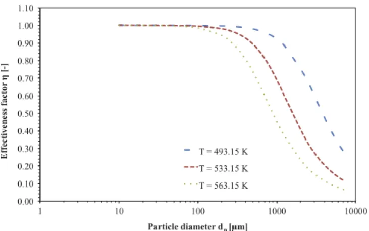
5.1. Intraparticle concentration profile
It is of interest to investigate the interaction between diffusion and reaction in a Fischer–Tropsch catalyst pellet. The mathematical model previously introduced was based on effectiveness factor defined as Eq.(22). A strong dependence of the effectiveness factor was found
Table 5
Data and operating conditions used to model the packed fixed bed reactor for Fischer Tropsch synthesis. Parameters Value Pout 20 bar T0 293.15 K WHSV 20–600 gsyngasmin" 1kg" 1 cat: θH2=CO 2 (–) α 0.9 (–) ϵ 0.4 (–) Tw 488.15–503.15 K μg;ma 2.4 ( 10" 5Pa s λg;H2 a 250 W m" 1K" 1 λg;COa 0.0376 W m" 1K" 1 λg;ma 0:134 W m" 1K" 1 aEstimated values for the inlet at T¼493.15 K
according to the pellet size (Fig. 2) whatever the operating tempera-ture. However it can be seen that, for very small catalyst particle ðdp¼ 90–100
μ
mÞ, the CO-based effectiveness factor is close to one.With increasing the particle diameter size and/or boosting the operating temperature, the effectiveness factor decreases to a rela-tively low value involving severe limitation of diffusion inside the pores. Moreover, the results show that, for pellets size of about 2–4 mm, the diffusion within the catalyst pore cannot be neglected. Thus, the assumption that the effectiveness factor is equal to one is verified as far as in the present model the catalyst particle diameter is 90
μ
m.5.2. Gas–liquid hydrocarbon phase ratio under typical operating conditions
As indicated previously, reactor simulation was chosen to be carried out by solving the species transport equations and the Brink-man equations for gaseous compounds only (Tw¼ 493:15 K and
Pout¼ 20 bar). Indeed under these operating conditions,
thermody-namics equilibrium calculations (National Institute of Standards and Technology (NIST), 2013) revealed that hydrocarbons from C1 to C6
were in gaseous phase whereas compounds from C7to C50where in
liquid phase. Simulation results reveal that the pseudo homogeneous model is relevant regarding gaseous versus liquid flow ratio (Table 6). ASF distribution was used to describe hydrocarbons production over C6and results highlight that 99% of the volumetric flow representing
more than 96% molar of total compounds are in the gas phase. 5.3. Influence of tube diameter on temperature profile and selectivity at constant WHSV
The effect in changing the tube diameter toward millimetric scale with regard to the behavior of the reactor is investigated. The first purpose was to carry out the study according to eight diameters of millimetric to centrimetric size using standard stainless steel tube
diameters, i.e. 1″, 3=4″, 5=8″, 1=2″, 3=8″, 1=4″, 1=8″ and 1=16″ with standard thicknesses. The first results in temperature contours and hot spot formation showed that no convergence was achieved for tube diameters higher than 1=4″ (6.35 mm). Actually for those diameters, temperature within the catalytic bed increases drastically with no possible control of the reaction heat release and the thermal runaway leads to undefined solutions of the simulation. This was observed whatever the chosen WHSV. Actually, this is explained by the activity of the catalyst associated to high effectiveness factor (
η
). Thus, the results reported here focus on diameters ranging from 0.88 mm to 3.11 mm as internal diamater (dR). It was decided toinvestigate the influence of the diameter without any dilution of the catalyst that would have allow the use of large tubes.
Space velocity ðWHSV ¼ 20 gsyngasmin" 1kgcat:" 1Þ, cooling
tem-perature (Tw¼ 493:15 K and molar ratio hydrogen to carbon
mon-oxide ð
θ
H2=CO¼ 2Þ were chosen as constant parameters. Thetwo-dimensional temperature contours are depicted for two different tubes diameters (Fig. 3).Fig. 3highlights the formation of hot spots as the tube diameter increases. For the lowest given diameter, i.e. 0.88 mm (Fig. 3a), isothermal contour arises (in yellow color) and the maximum reached temperature does not exceed 494.3 K. As the diameter rises, maximum temperature increases up to 621.4 K, i.e. temperature changes from yellow to red in color (Fig. 3b), hot spot appears and gets closer to inlet of the reactor. In all cases near the inlet region, the flow is heated up by the heat transfer fluid. Indeed heat transport by diffusion (black arrows) operates from the wall, that is a hot region near the inlet, towards the centerline and the coolest regions. Particularly when the hot spot arises, the heat is removed by the coolant fluid outside of the packed bed. In the vicinity of the hottest zone a part of the heat released is transported by thermal diffusion boosting the temperature increases of the reactor bulk flow in the coolest zone. For this reason the diffusive heat flux is substantially opposed to the convective heat flux (red arrows).
The axial temperature profile is illustrated inFig. 4for different pipe sizes reported in metric value.
It can be observed that better heat removal and a flat tem-perature profile within the bed can be obtained with lowest tube diameter. Between 0.88 mm and 2.00 mm inner tube diameter, the system removes efficiently the heat released during the synthesis; no thermal runaway is observed within the bed. Only a slight increase up to 6 K over the cooling temperature ðTwÞ is observed
when the diameters reaches 2.00 mm. Above 3.10 mm and as mentionned previously, thermal runaway occurs and temperature increasing is so drastic that no convergence of the simulation is possible. The thermal behavior reported inFig. 4is in agreement with the two-dimensional centimeter models developed by Jess and Kern (2012)andLee and Chung (2012) in centimeter tubes. They showed how the performance of the reactor and the maximal temperature reached are highly sensitive with tube diameters and catalyst particle size.
The maximal temperature Tmax within the bulk is correlated to
the tube diameter of the FT reactor (Fig. 5). As shown inFig. 5, space velocities in the range of 20–80 gsyngasmin" 1kgcat:" 1 seems to have
no effect on the maximal temperature. As the diameter decreases, the maximal temperature induced by the heat released by the FT synthesis decreases towards the setpoint temperature Tw. Actually,
for the studied diameters, the CO conversion does not change significantly in the given conditions of WHSV as the residence time is high enough. So, the total heat released rises with WHSV due to the total gas flow increasing. For smaller diameters, overall heat transfer coefficients are so high that no difference in Tmaxis observed
as WHSV increases. At a given WHSV, with increasing tube diameter, the heat removal from the core to the wall cooling decreases. Indeed when diameter increases, overall heat transfer coefficient gets lower and the ability of the reactor to remove reaction heat diminishes.
0.00 0.10 0.20 0.30 0.40 0.50 0.60 0.70 0.80 0.90 1.00 1.10 1 10 100 1000 10000 Effectiveness factor [-] Particle diameter dp [ m] T = 493.15 K T = 533.15 K T = 563.15 K
Fig. 2. Variation of effectiveness factor with pellet size for three different temperatures.
Table 6
Volume and molar fraction of compounds under FT operating conditions, dR¼ 1:75 mm, WHSV ¼ 70 gsyngasmin" 1kgcat:" 1.
Compounds Phase Production (493.15 K, 20 bar)
PvðL h" 1kgcat:" 1Þ Volume fraction (%) Molar fraction (%) H2O Gas 401.64 88.95 86.85 H2 Gas 2.08 0.46 0.45 CO Gas 20.01 4.43 4.33 C1–C6 Gas 26.02 5.76 5.63 C7–C50 Liquid 1.77 0.39 2.74
Fig. 3. Temperature contours, diffusive heat flux (black arrow) and convective heat flux (red arrow) within the fixed bed reactor under operating condition Tw¼ 493:15 K,
WHSV ¼ 20 gsyngasmin" 1kgcat:" 1for different tube diameters. (For interpretation of the references to color in this figure caption, the reader is referred to the web version of
Heat transfer resistance of the bed ðdR=8
λ
erÞ rises with the tubediameter whereas heat transfer resistance of the internal reactor ð1=
α
w;intÞ wall remains nearly constant (Fig. 6). Moreover asexpected the heat transfer resistance of the wall by conduction is negligible and closed to 1 ( 10" 4m2W" 1K" 1. This ability to
remove heat released changes so much that not only hot-spot appears but also as WHSV rises heat removal becomes too low to avoid temperature runaway.
Moreover it is particularly interesting to estimate the overall heat transfer coefficient Uoverall defined with the assumption that the
external heat transfer resistance of the shell side is negligible due the high flow velocity of the coolant. Therefore, the overall heat transfer coefficient can be written as
Uoverall¼ 1
α
w;int þ dR 8λ
er $ %" 1 ð44Þ For centimeter tube diameters the calculated overall heat transfer coefficients usually range from around 200–400 W m" 2K" 1(Philippe et al., 2009; Jess and Kern, 2012; Lee and Chung, 2012).
483.15 493.15 503.15 513.15 523.15 533.15 543.15 553.15 563.15 573.15 583.15 593.15 0 0.01 0.02 0.03 0.04 0.05 Centerline temperatur e T [K] Axial length z [m] 3.12 mm 3.10 mm 3.05 mm 2.75 mm 2.50 mm 2.00 mm 1.75 mm 0.88 mm
Fig. 4. Influence of the tube diameter on the temperature (r¼0) along axial direction of a cooled tubular fixed bed reactor ðWHSV ¼ 20 gsyngasmin" 1kgcat:" 1).
493.15 498.15 503.15 508.15 513.15 518.15 523.15 528.15 533.15 0.50 0.70 0.90 1.10 1.30 1.50 1.70 1.90 2.10 2.30 2.50 2.70 2.90 3.10 Tmax [K]
Inner diameter of reactor dR [mm]
70 g syngas/[min.kg_cat] 60 g syngas/[min.kg_cat] 50 g syngas/[min.kg_cat] 40 g syngas/[min.kg_cat] 30 g syngas/[min.kg_cat] 20 g syngas/[min.kg_cat]
Fig. 5. Maximal temperature versus tube diameter for different space velocity ðTw¼ 493:15 KÞ. 1.00E-05 5.10E-04 1.01E-03 1.51E-03 2.01E-03 2.51E-03 3.01E-03 3.51E-03 0.80 1.00 1.20 1.40 1.60 1.80 2.00 2.20 2.40 2.60 2.80 3.00 3.20
Heat transfer resistance U
overall
-1 [m 2 K 1 W -1]
Inner diameter of reactor dR [mm]
Overall thermal resistance Bed thermal resistance Internal wall thermal resistance
Fig. 6. Heat transfer resistance versus tube diameter reactor ðTw¼ 493:15 K;
WHSV ¼ 20 gsyngasmin" 1kgcat:" 1Þ.
0 500 1000 1500 2000 2500 3000 3500 0.00 0.01 0.01 0.02 0.02 0.03 0.03 0.04 0.04 0.05 0.05 overall [W m 2 K -1] Axial length z [m]
Fig. 7. Overall heat transfer coefficient along axial length for different tube diameters ðTw¼ 493:15 K; WHSV ¼ 20 gsyngasmin" 1kgcat:" 1Þ.
13.2% 13.4% 13.6% 13.8% 14.0% 14.2% 14.4% 84.0% 86.0% 88.0% 90.0% 92.0% 94.0% 96.0% 98.0% 100.0% 0.80 1.00 1.20 1.40 1.60 1.80 2.00 2.20 2.40 2.60 2.80 3.00 C1 - C 4 Selectivity [%] CO conversion and C 5+ selectivity [%]
Inner diameter of reactor dR [mm]
CO conversion [%] C5+ selectivity [%] C1-C4 selectivity [%]
Fig. 8. Effect of tube diameter on CO conversion with Tw¼ 493:15 K, P ¼20 bar and
WHSV ¼ 20 gsyngasmin" 1kgcat:" 1.
0.00 0.02 0.04 0.06 0.08 0.10 0.12 0.14 0.16 0.18 0.20 Fuel gas LPG
Gasoline Naphta Ker
osene Diesel Middle W ax Pr oductivity [kg h -1 kg cat. -1] 0.88 mm 1.75 mm 2.00 mm 2.50 mm 2.75 mm 3.05 mm 3.10 mm 3.11 mm Increasing diameter
Fig. 9. Effect of tube diameter on productivity of common hydrocarbon cut (fuel gas, liquid petroleum gas (LPG), gasoline, naphtha, jet fuel, diesel, middle distillate, wax) with Tw¼ 493:15 K, P ¼20 bar and WHSV ¼ 20 gsyngasmin" 1kgcat:" 1.
In this work, the overall heat transfer coefficients calculated are much higher (Fig. 7). The coefficient even reaches 3300 W m" 2K" 1
at the vicinity of the reactor inlet for a 0.88 mm tube diameter. This study reveals also the significant variation of the overall heat transfer along the axial direction z of the reactor. The value of the gas mixture thermal conductivity strongly associated to the thermal conductivity of hydrogen, increases in the heating zone involving the rise of the overall heat transfer coefficient. As the synthesis starts, the gas mixture conductivity of gas decreases drastically from 132 to 39 mW m" 1K" 1due to the consumption of hydrogen and
the decrease of gas velocity.
The effect of tube diameter on the conversion of carbon monoxide and the product selectivity is given byFig. 8. It can be seen that C1–C4 fraction increases due to the temperature
increases. CO conversion and C5 þ selectivity slightly decreases
with increasing of tube diameter.
The productivities of hydrocarbon cuts are computed from the recursive kinetics and are shown inFig. 9. The productivities in liquid transportation fuels (gasoline, Diesel, jet fuel) are found to be slightly affected by the tube diameter while the quantity in fuel gas increases drastically when the tube diameter is increased. 5.4. Influence of WHSV on product selectivity and productivity at constant tube diameter
The influence of space velocity on CO conversion, selectivities and hydrocarbon productivities are presented for two tube diameters: dR¼ 0:88 mm (Fig. 10) and dR¼ 2:75 mm (Fig. 11). These figures do
not exhibit sensitive differences except the C5 þproduction. Regarding
the 0.88 millimiter tube it can be observed that, up to a WHSV of 80 gsyngasmin" 1kgcat:" 1CO conversion remains approximately constant
ðXCO¼ 92%Þ whereas the C5 þ productivity, which is the total mass
flow rate of C5 þ hydrocarbons based on catalyst weight, increases
and then remains slightly unchanged ðPmC5 þ¼ 2:0 kg h" 1kgcat:" 1Þ.
Then, as soon as the space velocity reaches values higher than 90 gsyngasmin" 1kgcat:" 1, the conversion decreases and the productivity
remains constant ðPmC5 þ¼ 2:0 kg h " 1kg" 1
cat:Þ because the residence
time decreases below the time needed to convert efficiently the syngas into hydrocarbons. As regards the 2.75 mm tube (Fig. 11) selectivity of C5 þ decreases and CO conversion remains both roughly
constant up to a space velocity of 100 gsyngasmin" 1kgcat:" 1. Although
the C5 þ production is higher than within a 0.88 mm tube, an optimal
value of space velocity, around 180 gsyngasmin" 1kgcat:" 1, is needed to
ensure the maximal production of C5 þ. Productivity values of C5 þare
in agreement withSadeqzadeh et al. (2012)for millimeter-scale tubes and the production of light hydrocarbons increases with the rise in tube diameters. Moreover, bothFigs. 11 and 10highlight the weak
influence of WHSV on selectivity in C5 þ. Actually, a slight increase in
temperature around 503 K occurs with 2.75 mm tube and overall heat transfer coefficient is not much dependent on WHSV. High efficiency in heat transfer allows the release of reaction energy and thus prevents the enhancement of light hydrocarbons production.
5.5. Scale-up considerations
Scale-up calculations via numbering-up of tubes were carried out on the basis of the requirement for a production expressed in barrels per day (bpd) of C5 þ fraction. Because of the low
tem-perature rise within millimeter-scale geometry, a 2.75 mm tube was chosen. Moreover C5 þ selectivity remains higher than 83%
whatever the space velocity (Fig. 10) due to the high thermal performance to dissipate heat released. Pressure drops given by simulations for different space velocities as shown inFig. 12 are strictly linear and obey to an analogous Darcy's law for porous media owing to laminar flow regime because Reynolds number based on particle diameter (Rep) was in the range 0.04–1.
For a 2.75 mm diameter, the scale-up study consist in deter-mining the number of tubes needed to produce one barrel of liquid hydrocarbons ðNtubesÞ. According toTable 7, an optimal
production of 2943 kg h" 1m" 3
cat: is ranging around about
180–200 gsyngasmin" 1kgcat:" 1whereas with conventional reactors
(fixed bed or slurry), the catalyst productivity of liquid hydro-carbons does not exceed 400 kg h" 1m" 3
cat:(Oxford Catalyst, 2012).
This range of value is in agreement with the microreactor used by Velocys (Deshmukh et al., 2010).
0.00 0.25 0.50 0.75 1.00 1.25 1.50 1.75 2.00 2.25 2.50 0% 10% 20% 30% 40% 50% 60% 70% 80% 90% 100% 30 130 230 330 430 530 Pr oductivity [kg h -1 kg cat. -1] C O conversion and C 5+ selectivity [%]
WHSV [gsyngas min-1 kgcat.-1]
CO conversion C5+ selectivity Productivity of C5+ Productivity of C1-C2 Productivity of C3-C4
Fig. 10. CO conversion and hydrocarbon productivity versus space velocity WHSV for a millimeter-scale tube dR¼ 0:88 mm, Tw¼ 493:15 K.
0.00 0.25 0.50 0.75 1.00 1.25 1.50 1.75 2.00 2.25 2.50 0% 10% 20% 30% 40% 50% 60% 70% 80% 90% 100% 30 130 230 330 430 530 Pr oductivity [kg h -1 kg cat. -1] CO conversion and C 5+ selectivitity [%]
WHSV [gsyngas min-1 kgcat.-1]
CO conversion C5+ selectivity Productivity of C5+ Productivity of C1-C2 Productivity of C3-C4
Fig. 11. CO conversion and hydrocarbon productivity versus space velocity WHSV for a centimeter-scale tube dR¼ 2:75 mm, Tw¼ 493:15 K.
0 100 200 300 400 500 600 700 0 0.01 0.02 0.03 0.04 0.05 0.06 0.07 0.08 0.09 0.1 Pr essur e dr op [mbar] Axial length z [m] WHSV=600 g_syngas/min/kg_cat. WHSV=520 g_syngas/min/kg_cat. WHSV=440 g_syngas/min/kg_cat. WHSV=360 g_syngas/min/kg_cat. WHSV=280 g_syngas/min/kg_cat. WHSV=200 g_syngas/min/kg_cat.
Fig. 12. Pressure drop versus space velocity WHSV for a tube diameter dR¼ 2:75 mm, Tw¼ 493:15 K.
6. Conclusions
Simulation results based on the described two dimensional model have shown a high dependency of the thermal behavior with respect to the thermal conductivity of the gas mixture, which is linked to the hydrogen consumption, exhibiting a high thermal conductivity compared with other compounds, along the reactor. Although the viscosity and the heat capacity slightly change during synthesis, this variation does not cause the same variation of temperature within the bed. The simulations of different tube diameters of the fixed-bed reactor allowed to highlight the high performance of millimeter-scale for FT synthesis. No exact con-vergence was achieved for diameter tube higher than 3.11 mm due to the thermal runaway affecting the other variables strongly coupled. Therefore, in the work reported here using a kinetic associated with a highly active catalyst, the critical diameter involving a hot spot lower than 10 K is found to be lower 2.50 mm. No significant temperature rise occurs below this dia-meter range preventing the increase of light hydrocarbons selec-tivity. Millichannel catalytic reactor provides effective heat removal for this exothermic synthesis, leading to an isothermal temperature profile which induces low methane selectivity and production of long chain hydrocarbons. The campaign of simula-tions also allowed to find out an optimal space velocity to maximize the production rate of C5 þ. Results obtained from
scale-up study open a promising way to produce more hydro-carbons with compact module unit where temperature becomes a controllable parameter.
Nomenclature Greek letters
α
chain growth probability (dimensionless)α
w;int wall heat transfer coefficient (W m" 2K" 1)β
F Forchheimer coefficient (m" 1)
Δ
Hf ;i enthalpy of formation of specie i (J mol" 1)Δ
HR global heat of reaction of FT synthesis (J molCO" 1)ϵ
bed void fraction (dimensionless)ϵ
p catalyst permeability (dimensionless)η
effectiveness factor (dimensionless)λ
bed bed thermal conductivity (W m" 1K" 1)λ
ea effective axial thermal conductivity (W m" 1K" 1)λ
er effective radial thermal conductivity (W m" 1K" 1)λ
g;i thermal conductivity of gaseous specie i (W m" 1K" 1)λ
g;m thermal conductivity of gas mixture (W m" 1K" 1)λ
wall thermal conductivity of the wall (W m" 1K" 1)μ
g;i viscosity of gaseous specie i (Pa s)μ
g;m viscosity of gas mixture (Pa s)ϕ
Thiele's modulus (dimensionless)ρ
f density of gas mixture (kg m" 3)ρ
p density of particle catalyst (kg m" 3)
τ
p tortuosity (dimensionless)θ
H2=CO molar ratio H2/CO (dimensionless)Latin letters ji
! mass diffusional flux for the specie i (kg m" 2s" 1)
u
! velocity profile (m s" 1)
a pre-exponential factor in Arrhenius' law (m6kg cat " 1
mol" 1s" 1)
b pre-exponential factor in Arrhenius' law (m3mol" 1)
Ci molar concentration of specie i (mol m" 3)
d pre-exponential factor in Arrhenius' law (dimensionless)
dp pellet diameter (m)
dR inner tube diameter (m)
Dea effective axial dispersion coefficient (m2s" 1)
Deff ;H2;l effective diffusion coefficient of hydrogen (m2s" 1)
Der effective radial dispersion coefficient (m2s" 1)
e pre-exponential factor in Arrhenius' law (dimensionless)
F inlet mass flow (kg s" 1)
HeH2 Henry's coefficient (Pa m
3mol" 1)
I identity matrix (–)
K porous media permeability (m2)
k0
a apparent constant rate of consumption of CO
(m3kg cat" 1s" 1)
ka constant rate of consumption of CO
ðm6kgcat" 1mol" 1s" 1Þ
kb adsorption constant (m3mol" 1)
kFT kinetic constant of FT synthesis ðm6kgcat" 1mol" 1s" 1Þ L length of reactor (m)
m mass (kg)
N chain number of hydrocarbons (dimensionless) Ntubes number of tubes needed to produce one barrel of
liquid hydrocarbons ðC5 þÞ per day (tubes bpd" 1)
Pi partial pressure of specie i (Pa)
PC5 þ mass production of (kg h
" 1 m cat." 3)
Pout oulet pressure (Pa)
r radial length (m)
ri rate of consumption of specie i (mol s" 1kgcat" 1)
rCOeffective global reaction rate of CO consumption i
(mol s" 1kg cat" 1)
rCOsurface intrinsic reaction rate of CO consumption i
(mol s" 1kg cat" 1)
Rep Reynolds number (dimensionless)
S selectivity (dimensionless) T bulk temperature (K) T0 inlet temperature (K)
Tw cooling temperature(K)
uz axial velocity profile (m s" 1)
Uoverall overall thermal transmittance (W m" 2K" 1)
us;0 inlet velocity (m s" 1)
uwall velocity near the wall vicinity (m s" 1)
wi mass fraction of specie i (dimensionless) WHSV weight hourly space velocity ðg
syngasmin" 1kgcat:" 1Þ
XCO CO conversion (dimensionless)
Table 7
Results for the scale-up calculations for a 2.75 mm tube diameter, Tw¼ 493:15 K.
WHSV us;0 XCO SC5 þ PC5 þ Ntubes
ðgsyngasmin" 1kgcat:" 1Þ (mm s
" 1) (%) (%) ðkg h" 1m" 3 cat:Þ (tubes bpd " 1) 20 4.64 97.73 85.80 510.6 17484 30 6.96 94.54 85.80 741.3 12 042 40 9.28 93.70 85.78 979.9 9111 100 23.19 92.08 85.73 2409.2 3706 160 37.11 71.80 85.77 2939.7 3037 180 41.75 64.65 85.80 2943.3 3033 200 46.38 58.79 85.83 2939.4 3037 240 55.66 49.94 85.86 2926.0 3051 320 74.21 38.82 85.89 2893.7 3085 360 83.49 35.11 85.90 2877.3 3103 400 92.28 32.14 85.91 2860.8 3121 440 102.05 29.71 85.92 2844.2 3139 560 129.88 24.51 85.95 2794.8 3194 600 139.15 23.23 85.96 2778.6 3213
z axial direction (m)
cpg;m heat capacity of the specie i (J kg
" 1K" 1)
Acknowledgments
The authors are grateful to Pr. Fongarland Pascal, University Claude-Bernard Lyon 1, IRCELyon, for the helpful discussions concerning Fischer–Tropsch synthesis.
References
Anderson, R.B., Friedel, R.A., Storch, H.H., 1951. Fischer–Tropsch reaction mechan-ism involving stepwise growth of carbon chain. J. Chem. Phys. 19, 313–319.
Atwood, H.E., Bennett, C.O., 1979. Kinetics of the Fischer–Tropsch reaction over iron. Ind. Eng. Chem. Process Des. Dev. 18, 163–170.
Bauer, R., Schlunder, E., 1978a. Effective radial thermal conductivity of packing in gas flow. Part I. convective transport coefficient. Int. Chem. Eng. 18, 181–188.
Bauer, R., Schlunder, E., 1978b. Effective radial thermal conductivity of packing in gas flow. Part II. Thermal conductivity of the packing fraction without gas flow. Int. Chem. Eng 18, 181–188.
Borkink, J.G.H., Westerterp, K.R., 1992. Influence of tube and particle diameter on heat transport in packed beds. AIChE J 38, 703–715.
Brokaw, R.S., 1969. Predicting transport properties of dilute gases. Ind. Eng. Chem. Process Des. Dev. 8, 240–253.
Bub, G., Baerns, M., Büssemeier, B., Frohning, C., 1980. Prediction of the perfor-mance of catalytic fixed bed reactors for Fischer–Tropsch synthesis. Chem. Eng. Sci. 35, 348–355.
Cao, C., Hu, J., Li, S., Wilcox, W., Wang, Y., 2009. Intensified Fischer–Tropsch synthesis process with microchannel catalytic reactors. Catal. Today 140, 149–156.
Chambrey, S., Fongarland, P., Karaca, H., Piché, S., Griboval-Constant, A., Schweich, D., Luck, F., Savin, S., Khodakov, A.Y., 2011. Fischer–Tropsch synthesis in milli-fixed bed reactor: comparison with centimetric fixed bed and slurry stirred tank reactors. Catal. Today 171, 201–206.
Chukwudozie, C.P., Tyagi, M., Sears, S.O., White, C.D., 2012. Prediction of non-Darcy coefficients for inertial flows through the castlegate sandstone using image-based modeling. Transp. Porous Med. 95, 563–580.
Delgado, J.M.P.Q., 2006. A critical review of dispersion in packed beds. Heat Mass Transfer 42, 279–310.
Deshmukh, S.R., Tonkovich, A.L.Y., Jarosch, K.T., Schrader, L., Fitzgerald, S.P., Kilanowski, D.R., Lerou, J.J., Mazanec, T.J., 2010. Scale-up of microchannel reactors for Fischer–Tropsch synthesis. Ind. Eng. Chem. Res. 49, 10883–10888.
Dry, M.E., 2002. The Fischer–Tropsch process: 1950–2000. Catal. Today 71, 227–241.
Fuller, E.N., Ensley, K., Giddings, J.C., 1969. J. Phys. Chem. 73.
Fuller, E.N., Giddings, J.C., 1965. J. Gas Chromatogr. 3.
Fuller, E.N., Schettler, P.D., Giddings, J.C., 1966. Ind. Eng. Chem. 58.
Guillou, L., 2005. Synthèse de Fischer–Tropsch en réacteurs structurés àcatalyse supportée en paroi (Ph.D. thesis), Ecole Centrale Lille.
Huff, G.A., Satterfield, C.N., 1984. Intrinsic kinetics of the Fischer–Tropsch synthesis on a reduced fused-magnetite catalyst. Ind. Eng. Chem. Process Des. Dev. 23, 696–705.
Jess, A., Kern, C., 2009. Modeling of multi-tubular reactors for Fischer–Tropsch synthesis. Chem. Eng. Technol. 32, 1164–1175.
Jess, A., Kern, C., 2012. Influence of particle size and single-tube diameter on thermal behavior of Fischer–Tropsch reactors. Part I. Particle size variation for constant tube size and vice versa. Chem. Eng. Technol. 35, 369–378.
Jess, A., Popp, R., Hedden, K., 1999. Fischer–Tropsch-synthesis with nitrogen-rich syngas: fundamentals and reactor design aspects. Appl. Catal. A: General 186, 321–342.
Khodakov, A.Y., Chu, W., Fongarland, P., 2007. Advances in the development of novel cobalt Fischer–Tropsch catalysts for synthesis of long-chain hydrocarbons and clean fuels. Chem. Rev. 107, 1692–1744.
Knochen, J., Güttel, R., Knobloch, C., Turek, T., 2010. Fischer–Tropsch synthesis in milli-structured fixed-bed reactors: experimental study and scale-up consid-erations. Chem. Eng. Process.: Process Intensif. 49, 958–964.
Lee, T.S., Chung, J.N., 2012. Mathematical modeling and numerical simulation of a Fischer–Tropsch packed bed reactor and its thermal management for liquid hydrocarbon fuel production using biomass syngas. Energy Fuels 26, 1363–1379.
Marpu, D.R., 1995. Forchheimer and Brinkman extended Darcy flow model on natural convection in a vertical cylindrical porous annulus. Acta Mech. 109, 41–48.
Martin, H., Nilles, M., 1993. Radiale wärmeleitung in durchströmten schüttungs-rohren. Chem. Ing. Tech. 65, 1468–1477.
Myrstad, R., Eri, S., Pfeifer, P., Rytter, E., Holmen, A., 2009. Fischer–Tropsch synthesis in a microstructured reactor. Catal. Today 147 (Supplement), S301–S304. National Institute of Standards and Technology (NIST), 2013. Available on
〈http://webbook.nist.gov/chemistry/fluid/〉. Consulted September 9, 2013.
Newsome, D.S., 1980. The water-gas shift reaction. Catal. Rev. 21, 275–318.
Nield, D.A., Bejan, A., 2013. Convection in Porous Media. Springer, New York.
Outi, A., Rautavuoma, I., van der Baan, H.S., 1981. Kinetics and mechanism of the Fischer Tropsch hydrocarbon synthesis on a cobalt on alumina catalyst. Appl. Catal. 1, 247–272.
Oxford Catalyst, 2012. Available on 〈http://www.velocys.com〉, Consulted December 16, 2013.
Özgümüş, T., Mobedi, M., Özkol, U., Nakayama, A., 2013. Thermal dispersion in porous media—a review on the experimental studies for packed beds. Appl. Mech. Rev. 65, 031001.
Philippe, R., Lacroix, M., Dreibine, L., Pham-Huu, C., Edouard, D., Savin, S., Luck, F., Schweich, D., 2009. Effect of structure and thermal properties of a Fischer– Tropsch catalyst in a fixed bed. Catal. Today 147 (Supplement), S305–S312.
Poling, B., Prausnitz, J., Connell, J.O., 2000. The Properties of Gases and Liquids. McGraw Hill, New York.
Sadeqzadeh, M., Hong, J., Fongarland, P., Curulla-Ferré, D., Luck, F., Bousquet, J., Schweich, D., Khodakov, A.Y., 2012. Mechanistic modeling of cobalt based catalyst sintering in a fixed bed reactor under different conditions of Fischer– Tropsch synthesis. Ind. Eng. Chem. Res. 51, 11955–11964.
Sarup, B., Wojciechowski, B.W., 1989. Studies of the Fischer–Tropsch synthesis on a cobalt catalyst II. Kinetics of carbon monoxide conversion to methane and to higher hydrocarbons. Can. J. Chem. Eng. 67, 62–74.
Springer (Ed.), 2010. VDI Heat Atlas. VDI-Gesellschaft Verfahrenstechnik und Chemieingenieurwesen, second edition. VDI Gesellschaft.
Wang, Y.N., Xu, Y.Y., Li, Y.W., Zhao, Y.L., Zhang, B.J., 2003. Heterogeneous modeling for fixed-bed Fischer–Tropsch synthesis: reactor model and its applications. Chem. Eng. Sci. 58, 867–875.
Wu, J., Zhang, H., Ying, W., Fang, D., 2010. Simulation and analysis of a tubular fixed-bed Fischer–Tropsch synthesis reactor with co-based catalyst. Chem. Eng. Technol. 33, 1083–1092.
Yates, I.C., Satterfield, C.N., 1991. Intrinsic kinetics of the Fischer–Tropsch synthesis on a cobalt catalyst. Energy Fuels 5, 168–173.
Yaws, C., 1999. Chemical Properties Handbook: Physical, Thermodynamics, Envir-onmental Transport, Safety & Health Related Properties for Organic and Inorganic Chemicals. McGraw-Hill Education, New York.
Zimmerman, W.H., Bukur, D.B., 1990. Reaction kinetics over iron catalysts used for the Fischer–Tropsch synthesis. Can. J. Chem. Eng. 68, 292–301.