A R Y THE ANALYSIS OF A BUILDING FRAIME BY MECHANICAL METHODS
By
Holger Peter Mittet
B.S., University of Washington
. 193i
Submitted in Partial Fulfillment of the
Requirements for the Degree of
MASTER OF SCIENCE
from the
Massachusetts Institute of Technology
1938
Signature of Author
Department of Civil and Sanitary Engineering, May 19, 1938
Signature of Professor in Charge of Research
Signature of Chairman of epartment Committee on Graduate Students
Signature redacted
Signature redacted
Mr. George W. Swett
Secretary of the Faculty
Massachusetts Institute of Technology Cambridge, Mass.
Dear Sir:
In partial fulfillment of the requirements for the degree of Master of Science in Civil Engineering, I am submitting to you herewith my thesis entitled,
"THE ANALYSIS OF A BUILDING FRAME BY MECHANICAL
METHODS."-Respectfully yours,
Holger P. Mittet
Page Acknowledgement ... Synopsis . . . .. *00*0000*000000000* G0*00 Purpose ... Method ... Scope Re sults . . . .
The Beggs Deformeter
Principle of the Beggs Deformeter
Application of the Beggs Deformeter
Calibration of the Distortion Plugs
The Model ...
Applying the Deformeter to the Model
Errors of Deformeter Technique
Microscope and Readings
Summary
Analysis by the Beggs Deformeter
Calibration of the Deformeter ...
Properties of the Members of the Frame Analysis for Reactions ...
Interior Stresses by Beggs Deformeter 0
Analysis by the M. I. T. Moment Indicator Analysis for Column Moments
M; I. T. Moment Indicator with Spring Balance ...
Conclusions
Comparison of the Moment Indicator and the Beggs Deformeter ...
1 2 2 2 3 4 7 10 14 17 18 19 20 21 23 24 27 32
37
40Results ... .
Bibliography ...
Appendix A
Slope Deflection Solution
Appendix
Appendix B
Maxwell's Law Applied to the Beggs
Deformeter ...
C
Beggs Deformeter Analysis ...
49
53
Appendix CAnalysis by M. I. T.'Moment Indicator ...
41 42
43
ACKNOWILEDGEENT
The author desires to express gratitude for
the assistance from his advisor, >rofessor-J. B.
Wilbur, whose suggestions were a constant help
SYNOPSIS
Purpose
The object of this thesis was to study the stresses
in a building frame by mechanical methods.
Method
The stresses in the building frame were found by
mechanical analyses of a celluloid model. The model
used was a four story, symmetrical three-bay frame with
rigid supports.
The analytical solution was obtained with the slope
deflection equations, and the simultaneous calculator
was used for solving the equations. The mechanical
devices used in the analysis were the Beggs Deformeter
and the M. I. T. Moment Indicator. The reactions were
solved for by the deformeter; the internal stresses were
found by means of both the deformeter and the indicator.
Scope
The analysis was performed for one loading. This
was a one lb. wind load applied normal to the columns
at the level of the top girder. Since the structure was
symmetrical, the stresses in corresponding members were
equal by theory, and in the mechanical solution this
was used as a check.
The number of the tests waselimited by the time.
Many difficulties arose in the beginning of this study
spent in overcoming errors of operation, and developing
of the necessary skill.
The analysis by the Beggs Deformeter included the
reactions and the stresses in the center of the girders
of the outside bay. The M. I. T. Moment Indicator was
used to solve for internal moments. Two types of
indicator solutions were used; first, direct application
of the moment indicator by which relative moments were
found, the absolute values of the moments being
deter-mined by the application of the equations of statics;
and, second, direct determination of the moments by
means of the moment indicator used with a spring balance.
Results
The results for all stresses proved to agree very
closely with the theoretical solution. The moment
indicator proved to be the more easily applied
THE BEGGS DEFORMETER
The analysis of indeterminate structures by the
Beggs Deformeter is based on the same fundamental
prin-ciple as is the basis of many mathematical methods,
namely, Maxwell's Theorem of Reciprocal Displacement.
The essential difference between the mathematical and
mechanical methods of solution is that in model analysis
laborious calculations of required deflections are
re-placed by direct measurements. The Beggs method
ex-presses each indeterminate quantity as a function of a
known load and two measurable deflections, replacing
the solution of groups of simultaneous equations. Also
the model analysis is self checking since the solution
produces a-ll stress components by measured deflections,
and the three equations of statical equilibrium remain
for checking. The model takes into aooount the effect
of thrust and shear deformations, varying modulus of
elasticity, effect of brackets, and peculiar distribution
of stress around corners of frames, which are not taken
into account in the approximate theoretical solutions.
Principle of the Beggs Deformeter
The Beggs Deformeter is a mechanical application of
Maxwell's Law (Appendix 3) which may be stated as follows:
The distortion (either angular or linear and
measured in any given direction) of any
point a in a beam or frame due to a unit
load (either angular or linear and in any
distortion at the second point b due to a
unit load at the first point a, provided
that at each point the loads and distortions
are always measured in the same directions.
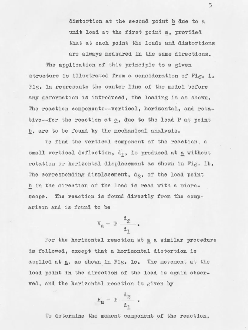
The application of this principle to a given
structure is illustrated from a consideration of Fig. 1.
Fig. la represents the center line of the model before
any deformation is introduced, the loading is as shown.
The reaction components--vertical, horizontal, and
rota-tive--for the reaction at a, due to the load P at point
b, are to be found by the mechanical analysis.
To find the vertical component of the reaction, a
small vertical deflection, d', is produced at a without
rotation or horizontal displacement as shown in Fig. lb.
The corresponding displacement, d2, of the load point b in the direction of the load is read with a
micro-scope. The reaction is found directly from the
comp-arison and is found to be
Va Cdi *
For the horizontal reaction at a a similar procedure
is followed, except that a horizontal distortion is
applied at a, as shown in Fig. lo. The movement at the
load point in the direction of the load is again
obser-ved, and the horizontal reaction is given by
d2
He
d (b) d b
[T~~~T
I I
I n7I7r7'
/
ci,(ol)
(c)
PRODUCED ay Q kEPORMevwER-p .6 777 77r) wr(a)
the support a is rotated through a small angle, defined
by the .value of d1 acting at a radius of unity, as shown in Fig. ld. The corresponding deflection, d2, at point b in the direction of the loading is measured. The moment is given by
Ma =P 2 dl
In this equation Ma is the bending moment that would be produced in a structure of the scale of the model. To convert this moment to the value for the full-scale structure, it is necessary to make allowance for the scale of the model as will be shown shortly.
Application of the Beggs Deformeter
The function of the Beggs Deformeter, Fig. 2, is to introduce at the support, or any section of the model, a given deformation. This deformation may be a pure
thrust, shear, or moment.
The gauge clamps of Fig. 2a are for the purpose of attaching the model to the table, and for producing the known distortion in the model. The deformeter con-sists of a.stationary member, A, screwed to the table, and a movable member, B, held to A by tension springs, but separated by the plugs. This is for the case of
reactions. If internal stresses are to be found the de-formeter is mounted on a frictionless bearing, and both gauge clamps are attached to the member at the section where the stresses are desired.
Spring P/u9 St4fionary gauqe P/ate
Wood screw0
0 80
Mvovb/e g9Qge C/am7P
Mode/c/amp Pin
(a)
Shear(b)
yy
)hr4s/ (C ) Adomen,' (d )distortions plugs. When the deformeter is attached to
the model normal (amber) plugs are used. The distortion
plugs vary from the normal plugs, and from each other
by a known amount, and produce distortions in the
direc-tion of the three biements of stress--shear, thrust,
and rotative. The removal of the normal plugs and
the insertion of the shear plugs, flattened on a face as
shown in Fig. 2b, produces a horizontal motionA,
without any vertical or angular motion. Similarly
the successive insertion of the small (white) and large
(red) plugs of Fig. 2c produces a vettical motion, 4Y., but does not allow vertical or horizontal motion. In
this manner known and controlled distortions of the
three stress elements are produced in the structure.
The deformation of the load point in the direction
of the loading is measured with a microscope. The
direction, sense, or sign of any stress component may be
noted by observation of the deformation of the model.
The microscopesemployed in measuring deflections are
optically inverting, so that the image in the microscope
moves in an opposite direction from the observed load
point. Accordingly, the following practical general rule
for determining the sense of any reaction or stress
comp-onent has been formulated: If the image of the load
point in the microscope moves in the direction of the
assumed load, the reaction component acts in the same
direction as the corresponding displacement of the
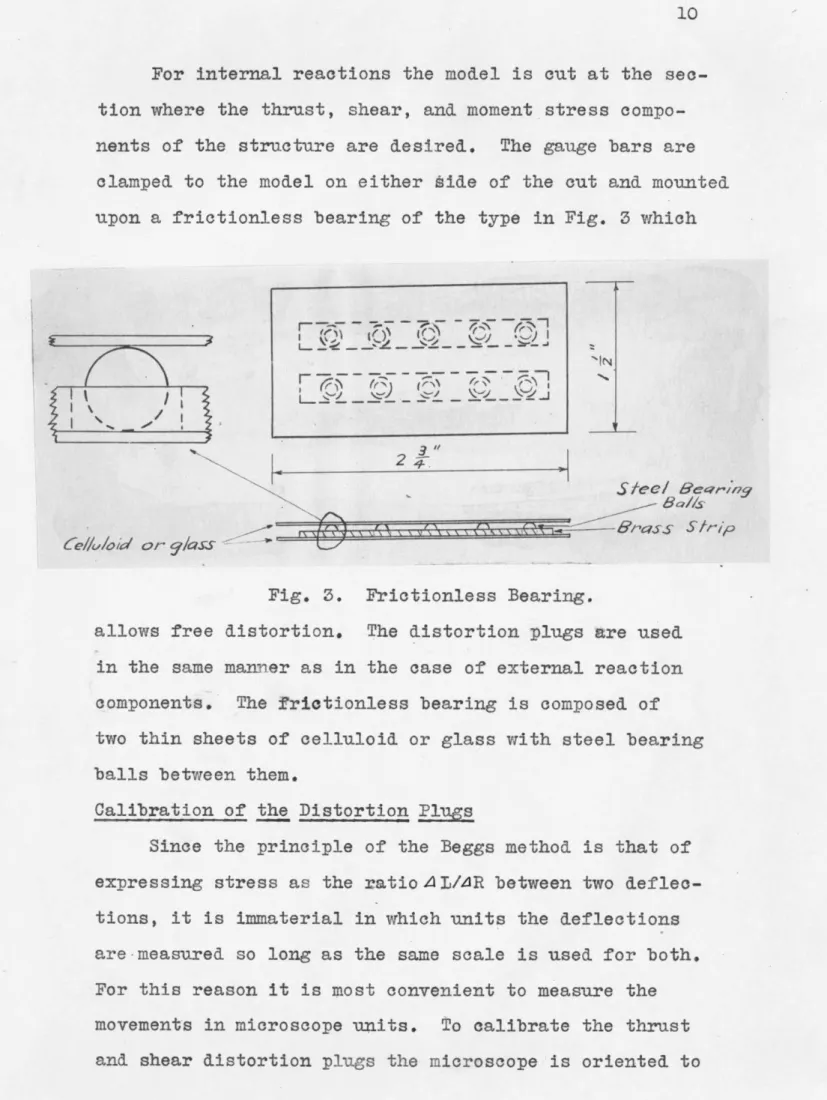
For internal reactions the model is cut at the
sec-tion where the thrust, shear, and moment stress
compo-nents of the structure are desired. The gauge bars are
clamped to the model on either iide of the cut and mounted
upon a frictionless bearing of the type in Fig. 3 which
"N
2 4
el6'rnss Strip
Fig. 3. Frictionless Bearing.
allows free distortion. The distortion plugs are used
in the same manner as in the case of external reaction
components. The frietionless bearing is composed of
two thin sheets of celluloid or glass with steel bearing
balls between them.
Calibration of the Distortion Plngs
Since the principle of the Beggs method is that of
expressing stress as the ratio AI/AR between two
deflec-tions, it is immaterial in which units the deflections
are-measured so long as the same scale is used for both.
For this reason it is most convenient to measure the
movements in microscope units. To calibrate the thrust
these movements the shear and thrust distortions plugs
are calibrated directly. The calibration can be checked by
direct calculation from the geometry of the gauges, and
the size of the distortion plugs. The size of the plugs
is converted to microscope units for this calculation.
Fig. 5b shows that the difference in the diameter of the
plugs, A, acts at fort* five degs to the direction of
the movement. Thus the movement is A/cos 45 degs or
1.414A.
The moment plugs cannot be calibrated directly. To
calibrate the moment plugs, attach a rigid arm, which
has several targets a given distance apart, to the
movable clamp as shown in Fig. 4. Orient a microscope
to read the several values of - as the rotation is
pro-duced by the movable clamp. The purpose of using several
targets is to obtain a good value of the rotation. From
these readings the calibration constant of the moment
pings is
d
If m is the number of microscope units per inch the
true angle is
Azz in radians = B 4A or m A =
.
md
The use of the calibration constant in practice involves
the scale of the model as shown by the following proof: To find the moment reaction at any point a in foot
A/ernq/e
wbde V Red' P/Mys - -c ~0 -- =.- - ~~~ N. 4 DETERM/NATION OF a AOR BEGG SMtMOMNr CONS TAv r APPA RA T-VS hi1I.4/44d ---
7--(a)
I.1-4 /4/44 /(b)
CAL C4'.A 7Opounds due to a load of one pound at any other point b, it will be necessary to find for the structure the
relation
Zab(ft. lbs.) zb (ft.) Jzz (radians)
This equation applies to the actual structure, and
to apply this to the model use primes to denote model
deflections, and if the structure is n times as large as
the model
zb(ft) 6nzb' (micro-Units)
m- .
12
The angular distortion at a for the structure will
be the same as that for the model and, from previous
equations,
e
A zz(radians) =m
Substituting, n-
Azb
(micro-units)
ba= 12Since n is the direct size rationof structure to model
in the same units, it will equal the inches of structure
per inch of model, or the scale of the model in feet per
inch is given by n/12. Therefore
Scale of model Movement of load point
Ft. lbs.
reaction in ft. per in. n model in micro-units j
'in structure
The Model
The rotation of all the elements of a member takes
place about the center of gravity of the active material
of the transverse section. Since the bending moments and
deflections are functidns of the coordinates, x, y, of
the centers of rotation of the elements in flexure, the
neutral axis of the model must be a scale representation
of that of the structure. Therefore, the first step in
making the model is to lay out the neutral axis to some
convenient scale. For concrete sections the entire
section is considered active.
Since the model represents the elastio properties
of the structure, the transverse dimensions at any point
on the model are not that of the structure to scale,
but depend upon the moment of inertia of the member.
The model is of a constant thickness, so the moment of
inertia is proportional to the cube of the depth. There
fore, the transverse dimension is
3 Depth = K I
in which K is the scale factor. This factor should be
selected so the model will be flexible.
The transverse dimensions of the members a're limited
by the size of the model clamp and by buckling-on narrow
members. The maximum size member that will fit in the
clamp is three-quarters of an inch. Members under one-quarter of an inch will be subject to buckling.
construo-tion of the model. The essential characteristic of the
material is that it will have a constant instantaneous
modulus of elasticity (E) within the small range of
stress produced by the deformations. Celluloid models
are subject to creep, but since the deformeter introduces
a given distortion the creep will have no effect upon
the elastic curve. The effect of creep is to lower E, but the rate of creep in the model will be uniform and E
will change uniformly.
Having determined the size of the members, the next
problem is to cut them to the proper transverse dimensions.
Precision is very necessary. For a one-half inch
trans-verse dimension an error of plus or minus one-hundredth
inch would produce a variation of about twelve per cent
in the moment of inertia of the member. The easiest way
to out the member is with the use of a circular table
saw. It is a simble matter to get the edges parallel,
but the difficulty lies in obtaining the proper dimension.
For this reason it is best to use the saw to cut the
depth closely to that desired, and make the exact
dimen-sion by hand work. This is done with a sharp plane or a
file. A vioe should be used that will not allow the
mem-ber to bend in the plane of the memmem-ber, for if bending
occurs the edges will not be parallel after cutting.
A micrometer is used to measure the dimension and to
obtain precision. By careful work the dimension may be
out very accurately. When the'transverse dimensions are
correct, out the members to the proper lengths. This
of the member should be in a plane.
For fabricating the structure, acetone is used. The
acetone will weld better if small particles of the
cellu-loid are dropped in the solution and allowed to dissolve.
Before welding the joints a full-scale drawing of the
model should be made. Attach the drawing to a drawing
board and place the members in their proper positions.
To prevent transverse movement of the members place
thumb tacks along the edges. Now, at the joint to be
welded, place several drops of acetone upon the surfaces
to be welded. Bring these surfaces carefully together
and place wtights upon the celluloid in order that no
member may move. Perform the same operation upon the
other joints, and allow the model to dry for one day.
In this manner the entire model may be fabricated in a
short time. Small pieces of paper should be placed under
any joint that is welded since the acetone will adhere
to the drawing as well as to the celluloid.
To find internal stresses the member must be cut.
Upon completing the analysis at this section obtain a
piece of the celluloid of the same width as the cut.
Then place several drops of acetone upon all surfaces to
be welded, put the piece of celluloid in the cut, and allow
sufficient drying time.
In order to allow correct distortion place the model
upon steel bearing balls on a horizontal surface. At
the points the balls are used place weights upon the model
three or four inches for a very flexible model.
Applying the Deformeter to the Model
For correct application of the Beggs Deformeter, but
one distortion, corresponding to one of the elements of
stress, should be produced by a given set of plugs. From
this it follows that the deformeter must be attached to
the model normal to the member, and that the center line
of the member must be located directly on the center line
of the movable clamp. When the gauge is attached to the
table some inclination will probably exist due to the
tendency of the screws to run in the grain of the wood,
and other unavoidable causes. When the clamp is at an
inclination to the member shear and thrust distortions
will be introduced simultaneously. This inclination
.must be determined.
To find the inclination insert the thrust plugs in
the deformeter and measure the horizontal deflection, A y, due to the inclination of the gauge as shown in Fig. 6.
hrust pla's pnser,'edI -I Shear p/u94 4 nser fed ravrge/ verte/ally - - - -over c/mp Fig. 6.
The thrust distortion, Zyy, is a known quantity.
deflection, . For any load the correction to apply for thrust will be Ayy/4 times the movement of the
load point due to shear distortion, and the correction
for shear will be 4 y/dyy times the movement of the load
point due to thrust distortion. The sign of the
correc-tion is determined by applying the general rule for the
sign, the correction being a negative factor.
No correction need be applied to the moment
compo-nent so long as the model is located accurately in the
center of the clamp since the movement is purely rotative,
and neither vertical nor horizontal movement occurs.
Large errors will occur if the member is not in the
center of the clamp since comparttively large vertical
deflections will be introduced.
The magnitude of the error will depend upon the
magnitude of the stress element. That is, if the thrust
is large a vertical movement when the shear distortion
is applied will cause considerable error if the deformeter
is not normal to the member.
Errors of Deformeter Technique
Even though the deformeter is correctly applied to
the model other errors are liable to appear. These are
the errors due to weakness of the tension springs of
the deformeter, and slippage between the model and the
clamps.
If the model is rigid the tension springs will not
have sufficient strength to overcome the resistance to
rotation necessary for moment distortion. Some external
distortion. A satisfactory way of overcoming the
resist-ance to rotation is to apply two small clamps and draw
the gauge bars together. This operation must be performed
carefully in order to produce the proper distortion.
When the resistance to distortion is large the
frictional resistance between the model and the gauge
might not be sufficient to prevent slippage. The member
must be fastened rigidly to the deformeter.
Producing deformation in a given member causes
dis-tortions in the other members of the model. In many
tests more than one set of deformeters is used on the
model at the same time. If the deformations produced by
a given deformeter cause slippage to occur in any other
deformeter the elastic curve of the model will be affected.
Slippage in any other deformeter occurs for the same
rea-sons as given above; namely, that the model is not tightly
attached to the deformeter, and that the tension springs
do not have sufficient resistance.
Some error will occur due to the manner in which the
deformeter grips the model for the case of internal
stresses. In theory deformations are applied at the point
the model is out, the whole being free to deform. Actually
a certain length is required to grip the model, and within
this length the member is prevented from deforming.
Microscope and Readings
Improper alignment of the microscope will cause the
same error as inclination of the deformeter to the
inclina-tion of the microscope to the correct direcinclina-tion. By
careful orientation of the microscope this will be
cor-rected. Care should also be taken to have the target fall
in the field of the microscope in order to prevent
parallax.
Targets are made by ink spots on a white background.
The spot used should not be the large ink dot, but
rather a very small speck. Care must be taken not to
lose the target, and it should be located by referenad
to a larger ink spot. Lighting should be produced by
a small light attached to the microscope and shining
directly on the target. Use a six or eight volt transformer
off a regular one hundred and ten circuit. A large light
on the model will produce temperature effects.
Summary
In the discussion many possible errors have been
pointed out. From this one can understand the necessity
of proper technique in the operation of the Beggs
Defor-meter. Careful application of the deformeter will give
ANALYSIS BY THE BEGGS DEFORMETER
Tests by the Beggs Deformeter were made on the four
story building frame of Fig. 7. The dimensions of the
model are given in the accompanying table. The material
used in the construction of the model was celluloid of
0.0645 inhhes thickness. The depth of the members was
made proportional to the cube root of the moment of
iner-tia of the full-scale sections. The neutral axis line
diagram of the model was at a scale of one inch equaled
two feet of the structure. Since the analysis was not
for an existing structure, the transverse dimensions
obtained by cutting the celluloid with a circular table
saw, as previously described, were used. In order to
obtain a simplified analytical solution, and to make
available checks on the mechanical analysis, the model
was made symmetrical. Acetone was used in the fabrication.
Calibration of the Deformeter
The calibration of the shear and thrust distortion
plugs was obtained by direct observations of the
move-ment of the movable clamp of th& deformeter. The
micro-scope used was a Spencer Micromicro-scope, number 202345.
Between the dark cross-hairs of the microscope four
hun-dred units on the vernier were measured. -A single unit
of the vernier equaled 0.0000375 inches.
%To find the moment constant,
e,
a rigid arm, with targets at one-half inch spacing, was attached to theI?
S
r
-/ - --- - - - Oil--- - ---- ---all pBi/
777 20' j 0"47;'
I
7- 70' 0" I-N7 -1 S~frn~At
7.
8ui/dn
9Frame
V /*
Cv~ I~?) N.PROPERTIES OF THE MEMBERS OF FRAME
Bar Width Relative I Relative I Length Rigidity Ratio
In. d3 I Feet min. E-F 0.750 0.4219 21.917 20 1.0958 F-G "T T I IT I-J " " t I J-K T IT T M-N I T TI I N-0 I T I" "T R-S 0.450 0.09112 4.734 0.2367 S-T " " " A-E 0.453 0.09296 4.829 11 0.439 B-F 0.766 0.44946 23.349 11 2.123 E-I 0.401 0.06448 3.350 13 0.258 F-J 0.623 0.2418 12.561 " 0.9662 I-M 0.339 0.03896 2.024 0.1557 J-N 0.453 0.09296 4.829 " 0.3715 M-R 0.268 0.01935 1.0 " 0.0769 N-S T IT TI
fastened to the table. The deflections of the targets,
A, produced by inserting the moment plugs were measured
for the four points on the rigid arm. From the measured
deflections the value of
e
was calculated in microscope units per inch.To obtain a check upon the calibration of the
dis-tortion plugs the sizes of the plugs were measured with
a micrometer, and from the geometry of the deformeter
the calibration constants were oaieuited. The values
accepted as the more accurate were the measured distortions
since the calculated values could not be obtained with
the refinement of the microscope.
The complete set of microscope readings and the
calculations of the constants are given in Appendix C.
The following are the calibration constants of the Beggs
Deformeter for the microscope used:
Movement of Shear Plugs =1360 micro units
Movement of Thrust Plugs =1376 " "
Moment Constant
e
=1849 T /in.Analysis for Reactions
The first tests made on the model were for the
re-actions. At the points A, B, 0, and D of the model
de-formeters were mounted. The end of each of the members
was fastened to the movable gauge bar, and the other gauge
bar was fastened to the table. Inserting the distortion
plugs in the deformeter, the shear, thrust, and rotative
reaction components were introduced at the reactions.
acting normal to the columns. By orienting the
micro-scope at the load point in the direction of the load the
deformations of the load point, produced by the
distor-tion plugs at the reacdistor-tions, were measured. Each
re-action component was calculated from one of the
follow-ing equations: V =Z lbs. dl H d2 lbs. d2 M = n- ft. lbs.
in which d2 was the movement of the load point in the
direction of the load produced by the distortion plugs
corresponding to the given reaction component, dl was
the equivalent distortion at the reaction, n the scale
of the model in feet perzInch, and
e
the moment constant. The symmetry of the structure was used in the analy-sis. Readings were taken for the load acting at bothpoints R and V. By theory, neglecting the direct stress
in the members, for the load acting at either side of the structure the two outside columns and the two interior columns will have reaction components of equal magnitude.
The results of the horizontal, vertical, and moment components of the reactions are shown in Fig. 8. The
mechanical solution is given in Appendix 0, and the anal-ytical solution is given in Appendix A.
Iv I-c vc 0. 7/q Ilbs. -0.72 Al o.7/87 n 0. 1/47 to~s o. //4f~7
1,6s.
- o./0? ii o. /157 n 0.825 /hs -0.8//0 0.7/03 i " 0.0/6 /b. Ve -0.00745' i -0.0//69iin 0.383 0. 374 0.88Q4-/hs. 'I 'I 2.885 //s. 4- 2.95 I 2. 7929 op 0.0342 /bs. Vc- 0.0 372 -0.01/69 0.3,8 16s H-0. 0.3843384
1/ f 2.8 '5 f /bs 4 - 2.8? o Fj 2. 7926 , n 0.676 V -0.682 0.7/87 0.1/02 Ho - 0 -019 0.1/57 0.7c/ 44-0.786 0. 7/03 COND/7~OAS OF LOADING WVinc lood a0 V W/1d load a / R 7YbeoreticQl VQ/ues by 8egs by 8egsfor u-/4d load a7 V
FiG. c. 0sc-- 4 OF I-YIosOs -oe R-,qcrovs MA k} I VA / 2 3 3 11D
V
lbs. 'I ,s. I ft / ,, I II I / 2 3"V J,
The two solutions by the Beggs method check closely.
The largest percentage differences occur for the vertical
reactions of the interior columns. This is due to the
small magnitude of these reactions. The most marked
difference between the mechanical and the analytical
solutions is also in the vertical reactions of the
in-terior columns. In this case the reaction by the two
solutions is of opposite sign. The absolute value of the
error is small since the center columns have a very small
direct stress.
robable errors may be contributed to neglecting
the direct stress factor in the theoretical solution,
application of the deformeter, incorrect readings of the
microscope, or some error in construction of the model.
For the interior vertical reactions the error in
sign must be attributed either to the model or the direct
stress in the members. Special care was taken in
micro-scope observation for these reactions, and also in the
application of the deformeter. Since the value of the
component was small the error of direction is not of
great importance. All other results check the
theo-retical solution within reasonable limits. The check
of statical equilibrium for the mechanical analysis
indicates that the solution was correct for the model.
The largest error of the equilibrium check was three per
cent.
Interior Stresses b B Deformeter
to the table, and the deformeter was applied at the
cen-ter of the girders of the outside bay. Only one
defor-meter was used. This deformeter was applied at the
cen-ter of the girder, and mounted upon a frictionless
bearing. In the application of the deformeter the
mem-ber was cut and the gauge bars were attached to the cut
ends. The stresses at the several sections were found
for the same loading as previously considered, again
using the symmetry of the structure as a check.
Since the model was cut for each girder it was
necessary to weld the member upon completion of the
analysis. This was a distinct disadvantage and caused
considerable delay because of the time necessary for drying.
Calculations of the stress components from the
ob-served deflections of the load points are given in
Appendix C, and the results are shown in Figs. 9 and 10.
The results for the internal stresses were not as
satis-factory as for the reactions. Using the equations of
statical equilibrium to find the reaction components at
D did not give results that checked the previous analysis.
The value of the moment component contained a very large
error. However, this may-be attributed to the length of
the lever arms to the upper girders. An error of
one-hundredth lb. in the direct stress of the top girder
would result in about a fifty per cent error in the moment
at D. For this reason it would be impractical to use
(0/25/) 0/072 0 /f (0. oS4c) 0./V Z (.0/5) 0,006-, (0. 0/65) 0.004 G
(
(2.5o72) 0.1/57 2. 2f57 ( -24s) 02(/0)
(1.344) /A" 9q (0. 2075 1. /757 (.43 q4) 1. 2518 (0./652 (0,. /co06) 0.1/420 /0')
)
4I
S//b.p
UN I TSSheoa- ond thl-ust
-AIMOm7en* -
a.
/bs. L A nalyfica/ Resul*s B0 ckes I./2, 0.,643O.ers 7 P 8E6G'S ANA 4 Ys/s
/,6s
-(2. 5072) 22?Ad 1?61 9~' (0. //356 .~ 'O. 2)5) 0. 2135 (.4344) qdo 4q 0 10.20) i0';9i) /. 4394) 1.322 0.172 AO 605) 0. /4 I4 (-WI T S Shea,' cnd /hruS/ -Aloments - f /bs.
t
/bs.A na/y ica/ Rewsus In
gracre.As
H 0. 6377 or /TEGGS ANALYS/s (0. O's*) 0.0 (0o/s) (0.0/65) 0 G F/G. /. Rx-svirsthe bearing upon which the gauges were mounted allowed
free movement, the microscope readings were not
consis-tent enough to insure correct results. This condition
was especially true for the top girder where the model
was not sufficiently rigid. The Beggs Deformeter did
not prove satisfactory for determining the internal
ANALYSIS BY THE M. I. T. MOMENT INDICATOR
The theory of the moment indicator is explained in
Appendix D.
Since celluloid creeps under a given load, the
defor-mations produced by a load would not occur instantaneously,
but considerable time would have to pass before the model
would stop creeping. The strains due to the creep are
proportional to the fiber stresses acting, and the effect
of the creepcorresponds to a lowering of the modulus of
elasticity (E). Although E of the celluloid changes with
time, the instantaneous value is constant. As a result
if a given deformation is applied to the model the elastic
curve will remain the same as for the condition of a
constant E. For this reason in the application of the
moment indicator a given deformation of the load point
in the direction of the load was applied.
Analysis for Column Moments
In the first tests on the model by the moment
indica-tor (Fig. 11) the instrument was applied to the columns
F S1 measered here for "A
Fig. 11.
of the second story across the entire frame. The equation
6EI&
M= ,
is a function of the moment of inertia, E of the member,
and the span of the moment indicator. By the use of the
indicator the relative values of the moment for two
sec-tions-of the member may be found. From statics, the
shear at the story times the distance between the
sec-tions at which the relative moments were found equals the
sum of the moments at the given sections. Therefore, to
solve the moments at the given sections' the indicator was
attached to each column symmetrically and the relative
moments at the sections were found. The sum of these
moments was equal to the shear in the story (one lb.)
times the span of the indicator expressed in the scale
of the structure. Since the relative values of the
moments and the sum of the moments were known, the moments
were calculated directly.
The indicator was attached to the model by two pins
on a transverse section. This caused some of the
defor-mation measured at points a and b of Fig. 11 to be shear
distortion. Correction for the shear distortion is given
by the expression
A =0.0636&9( 6a b
in which d is the depth of the section and A is the
cor-rection for shear distortion which is to be subtracted from
each reading. The proof of this is given in Appendix D.
From the moments at the measured sections the end
(2.34?4) 2. 235' /K
Its-2.48 (2.4375) ~beoa'e/l-a/ Resvll/s #* "0 m ne4 -, 8rqckretsOrdinates plotted on comprersrsn e dye
Fla.
/2
MOMENTS BY MOMENT /N/D/CATORI1 (0.8424) .?3 2 .0.045 (0e763) (2.3434) '3f I 2.445 (2.43 75) 0.8424) 1 0.9,: (0. 007c /m7 3) /47 I FY. /hr.
The results are given in Fig. 12.
The greatest discrepancy occured for the end moments
of the exterior columns. The model was not originally
constructed for use with the moment indicator, and the
outside columns were too narrow for accurate results.
Also the material was not sufficiently thick. The
in-terior columns were of greater depth and as a result
better results were obtained. Even though the model was
not well adapted to the M. I. T. Moment Indicator, the
largest error of the end moments was six per cent,
considering the theoretical correct.
The same tests as just described were performed with
a moment indicator of the type of Fig. 13. This indicator
attached to the neutral axis of the member and a
cor-rection of shear was unnecessary. The indicator has a
L
A S
Fig. 13.
magnifying device and the analysis is made for but one
section for a. given setup. This indicator was constructed
for rigid models and was not well adapted to the model
of the building frame.
The calculations of the moments from the readings of
the indicator are given in Appendix D, and Fig. 14 shows
(2.3434) 2.32 I 4 F 2.4? (2.43 75) Theo,-elfced/ Resu/&fs Moments: Ft /bs /;f 8rackels
Sl os : Ordnates l/tedoncongresson edge
AFo.4 O-VTS a K MOAeN-/- /NO/Cd4 rOR
f. 84 24) o. Ji// I IJ1 (2-3434) 2.38Q // o. 84 24) 0.O55 L E 0.8/9 (0.J763) 2.42 (2.4375) | C7 0. 77 (0.8763)
F1 C. / 4
six per cent in magnitude.
M. I. T. Moment Indicator with Spring Balance
For the moments in the girders there were no equa-tions of statics available to convert the relative-moments to absolute values. This was overcome by the use of the
spring balance which was developed in the M. I. T. Structu-ral Analysis Labratory. The theory and calibration of
the spring balance is given in Appendix D. The calibration was performed upon a cantilever beam. By the use of the calibration constant developed the moment at any section was measured directly from the distortions measured on the spring balance and the moment indicator. The spring balance was made out of the same material as the model in order to eliminate the creep factor.
The tests made on the model by the moment indica-tor with the spring balance were for the outside bay, the same as the solution by the Beggs Method. The moment indicator used was the one illustrated by the diagramatic sketch in Fig. 13. Moments at two sections on each girder were found in the analysis, and from these the end moments were calculated as given in Appendix D. The results are shown in Fig. 15. These results are much more satisfactory than those by the Beggs method. The largest discrepancy was in the top girder. The load was applied at the top girder, and the method of applica-tion of the load did not allow the frame to distort
/ 325 P.4 46 -T 0. 906e?1 - (1. 0S57) 00S-2.4653 (2.193.P) 2.1.?34 2.249 (2.1 29) .4/6 1.4 G4? I/i
(Tbhorebical
r-eSulis ?n brackets)Momeons
: F /,s.S1 ns :Ordn/es p/ / Med onconmp-essvO edg e
7G
/5.
Ao"E-Nrs By M/77'T
1.664
(/ 77/)
777
and the top girder was distorted by the weld from the Beggs analysis. These conditions were a decided handi-cap in the moment indicator solution.
The values of the end moments agreed very closely with the analytical solution. This close agreement
indicates that the the Beggs solution was in considerable error.
CONCLUSIONS
Comparison of the Moment Indicator and the Beggs Deformeter
The model used kt.ithis study was designed for
analysis by the Beggs Deformeter, and the analysis by
the moment indicator was made as a supplementary study.
The conditions for the moment indicator were not ideal.
First, the material of which the model was made was too.
thin for the indicator; second, the depth of the sections
was limited by the limitations of the deformeter and
some 6f the sections were very flexible-; and third, the
analysis was first completed by the Beggs method which
involved cutting the members, this causing discrepencies
in the model.
Even with these difficulties the M. I. T. Moment
Indicator gave more accurate results for the internal
stresses. The Beggs Deformeter did not give satisfaction
for these stresses.
The best use of the Beggs method is for external
reactions. Using the proper technique of operation the
deformeter presents a reliable method to obtain external
reactions. All three elements of stress are found from
one setup. For internal stresses the three elements of
stress are also found from one setup, but the member must be cut and the time for welding makes the method
impractical if the time of the analysis is of importance.
The deformeter may be applied to a member of any shape
The moment indicator presents a method of analysis
that is also simple and direct. For any one setup the moment is the only stress element that may be calculated, but the other elements -may be calculated from the moments.
Stress analysis of a structure would involve finding the
moments at all sections, and it is a simple matter to
find the shear and thrust at any section from the moments
and the laws of statical equilibrium. The indicator may
be applied only to straight sections, and if the moment
of inertia varies calculations will be necessary to find
the moments.
Results
The mechanical analysis presented results that were
in very close agreement with the theoretical slope
deflec-tion analysis. The major discrepencies that were present
have been accounted for in the body of this paper.
The use of the mechanical analysis is not of
advan-tage for structures that may be easily analyzed by the
classical methods of approach, but its use would be
BIBLIOGRAPHY
Beggs, G. E.
Coultas, H. W.
Coultas, H. W.
Lobban, C. H.
"An Accurate Mechanical Solution of
Statically Indeterminate Structures
by use of Paper Models and Special
Gages." Proceedings of the American Concrete Institute, Vol. XVIII. 1922.
"Design of Elastic Structures from Paper Models." ibid., Vol. XIX. 1923
"The Use of Models in the Solution of Statically Indeterminate Structures."
Journal of the Franklin Institute,
Vol. 203. March 1927.
"Experimental Structural Engineering." The Structural Engineer, Vol VIII No. 8. Aug. 1930
and Lawton, V. H. "An Example of the Mechanical Solution of a Statically
Indeterminate Structure." ibid,
Vol. VIII No. 10. Oct.1930. "Mechanical Methods of Solution of
Stresses in Frames." Institution of Engineers and Shipbuilders in Scot-land, Vol. LXXVII. Dec. 19, 1933.
McCullough, C. B. and Thayer, E. S. Elastic Arch Bridges. John Wiley and SbnmB,Inc.
Pippar and Baker The Analysis of Engineering Structures. Longmans, London.
Whitaker, H. A.
Wilbur, J. B.
"Mechanical Methods for the Analysis of Statically Indeterminate Structures. "
The Structural Engineer, Vol. XII, No. 12. April 1934.
"Model Analysis of Structures." Journal of. the Boston Society of Civil Engineers, Volume XXV, No. 1. January 1938.
V2 ' " 2nd
(liv# " d tM ab,'
(EF)
(2/AE *2" 2/4+
W,
)(ZEO,)
+/i~ (2 E,-)+
Z'/-EOE,) -&E(6E'!
9|-
/G
(6C
S) =0
(3
o66)(2 EVE) - '5(2E6,-)+0 2-0(2E8,)-2 437(6E01) - 2 2(6C)= 0.()
(2H +#2A2Ai,)2EG, ) ,/E K2E1 ) t/"2zE ee) +/,C2E)-f/f6E) - /r6 (6E9) =08 0/9(2EG,)+c. 252P(2[E) + /0 iZE6s) 0. /537(2E04)-0Z 5Pf6 E O$) - o /537 rE tP) O E7 2
(KI) (2W,+2/Kn 2/
fe)(2 Ey) *
he, (2 E9,)+AM (2 EG/+Kre (2Ee )
-/kZ,(6E Ys)-/f'e
(6 E 4)
02.65GP(2 E6) )+0. /557(2e) E 7, )c/ 5(2E,)+C76CE9,2E) )-o
/567(6E
s) ~00769 (6E/)=0 Eg 3(c')
(26e4 +2/es )(2E~e) + /fey~(2E~,k+/kesf2E~s) - /eu (6EVG) =0
0. 6 27Z(2L6& 40676726,e) -0 2367(2E6s) -0. 076(76E.) =a 4
(F) (2 /f -E + 2/1r', 2A,' F'-)2rs) KE( E')Kr 2~ ) -(E~s -e ( E--ta 6E )' 0
/.6574 (2E ) + 095Y(ZEQE2 -40. 7662 (2 E-0) -2. /2 7 (6 E)-0.9662 (6 E A= Eg 5 (J )
112ffv
4 Mr42re+2 e(E41Y'sv12E,)
0- 4AV(2E, ) e 2e +/rj'y (2E CO,) -/f ? A;r 6 E P2 1 0(?/544(2E6'J) -l0 94'(2OE,)
40662(2Eer)
4037/S(2E) -0
7662(6E-2)0-7/6E
,) =oEg
(IW (2/NM*Zk
rtZ/6$o
NO2KN5)(2E~g)
+iv(E~)
t+/6sj2E~j )'Ao(2
E8
0)
)+(r(E
2K>(E
-
/fas(6EV%)
6, 87S8(2Eyj
O/5J'(2Gbc+ 37/5(2EOs+20769(2EQs)-0 37/S(6EfPs) -Q6276'?(6E
G)
='0
Eg . 7
(5) (2se +,2/N +2r(2EQ) )+/sE (2E)s' s/(2E) +1sr(ZEr) -AsN 4 ) -0
PJfAop-y heighj+
EndAWonen/s=O
I/
4 2.634(2
E6r )
--l
7S6(6~
E/)
- /2. 78P(2 EOg-49
2/'6E
V2 =0
/8
2f2EWE/
(35 +29,
-6
02
-+
2E/I~-(38--3O.,
-6
Y
') jfO2
/3
#/
512OEj
-'+ 5~41/2E6',) y7c2(2E9G,)+5772 (2E,) -4
296gf6EV'
2)=
/3 2f2Eg 97,)-6E is- 2E/ (8$,+ ' me -1-=
/3
+ 0
98422E9EkO
734
2(2Ev)+,} 2.221(2E6,1b+ 222
4712E6) -z/'o'(6Eff)= =
13 2f2E/(4(3-M R-6)-2E/s/86 -6 4) =0
3 +0. 12 2P2Ee)+1 .0 46/*(2EG0m) 40. 46/4(2E46) -0 6/5~2(6E @4 ) =0
2 EOE
=-AO.
37
2
E- = 0, 6 316 2 E, 4.46o?3
2 E,, =0. 73 7 2 E04= 40. 9'5-2 EO. 40, 572 2EZe
=+ 2. 5-R6 2Ex = 0. ? 37 6 =+ /,19 5- 5' GEV2= +4 5396 EVg .+
/36
6EL
424
J26
Is f/or2ndf/wr
3rdf/cvr
41h4jcr
E
//
BENDING MOMENTS IN THE NEMBERS
Clockwise moments are positive
MA = 0.439 ( 0.337- 1.955 ) -0.7103 MB = 2.123
(
0.6396-1.955)
- 2.7926 0.439 ( 0.674- 1.955 ) -0.5623 MEF 1.0958(
0.674+ 0.6396 )= +1.4394 = 0.258( 0.674+ 0.4685- 4.539 )= -0.8763 MFE =1..0 9 5 8 ( 1.2792+ 0.337 )= +1.7710 MFB--2.123(
1.2792- 1.955 )- -1.4347 MFG= 1.0958 ( 1.2792t 0.6396 )= -2.1026 MFJ =0.9 6 6 2 ( 1.2792- 0.737- 4.539 )= *2.4375 MIEm -0.258 ( 0.9374+0.337-4.539 )= -0.8424 M Ij=1.0958 ( M.IMr-001557(
MJI - l.0958 MJF= 0.9662 ( MJ -- 1. 0 958 M JN' .3715 =0.1557 ( MICR1.0958 MMR=00769 MNm 1.0958(
MNJZ 0,3715 ( MNO= 1.0958(
MNS=0.0769 0.937t 0.737 )= +1.8344 0.937+ 0.858- 8.134) - -0.9873 06685 +1.474 )= 2.1286 1.474+ 0.6396- 4.539)= -2.3434 1.474+ 0.737 )= +2.4228 1.474+ 0.572 -8.136 )= -2.2624 1.716+0.4685-8.136 )= -0.9266 1.716+0.572 )= *2.5072 1.716t 2.586-24.826 )= -1.5783 1.144+ 0.858 )= +2.1938 1.144+ 0.737- 8.136 )= -2.3237 1.144t 0.572 )- + 1.8804 1.1441t0.937 -24.826 )= -1.7491- 0.0769 ( 5.172t0.858-24.826 ) = -1.4454 M RM MRS MSR MSN MST
DIRECT STRESS IN COLUMNS + is tension -- is compression Member MRS + MSR 20 0.12509 = 20 IE = 0.36014J+ M 20 0.55824 MEFl1 MFE 20 MST+ MTS- MRS-MSR SN- ;-20 BT - 2 -20 1.446+ 1.0557 -+ 0.12509 20 2.5072+2.1938 0.12509+ =+ 0.3601 20 1.8344+ 2.1286 0.3601+ = +-0.5582 20 1.4394+ 1.771 0.5582+ = +-0.7187 20 By symmetry YT - iTS 0.06654- 0.12509,=- -0.05855 Similar expressions are obtained for the
other interior columns
NJ = -0.05855 0.18804- 0.23505= -0.10556 0.2367 ( 5.172 -0.937 ) = +1.4460 = 0.2367 ( 1.874 +2.586 ) =
+1.0557
= 0.0769 ( 1.8741- 0.572 -24.826 ) = - 1.7210 = 0.2367 ( 1.874+ 0.937 )= +0.6654 RM MI EAJF = -0.10556 + 0.24228 - 0.19815 - 0.06143 FB =-0.06143-t 0.21 026 - 0.16052= - 0.01169 SKEAR IN COLUMNS Member MRp + MIA _ 1.445 +1.5783 13 = 0.2326 0.9266+- 0.9873 13 0.8424+-0.8763 13 0.5623-0.7103 11 1.7210 +1.7491 13 2.3237+ 2.2624 13 2.3434-+ 2.4375 13 = 0.1472 0.1322 = 0.1157 0.2669 = 0.3528 = 0.3678 1.4347* 2.7926 11 = 0.3843 RM -13 El FA SN NJ JF BF
APPENDIX B
MAXWEL'S LAW APPLIED TO THE BEGGS DEFORMETER
If, in the simple beam span (Fig.16 ), a 'mit vertical load be applied at any point a producing
moments mna throughout the length of the beam, the
vertical displacement of any other point b is given by
the expression
7 as
ba
mbma
where the term &ba is deflection of b due to a unit
load at a,
ia - the moment at any section of the beam due solely to the unit load at
point a, and
mb - the corresponding moment due solely
to a unit auxiliary load applied
at point b.
In the subscript notation used for the deflection
the first subscript defines the point at which the defledtion is to be measured, and the second subscript the position of the load.
If, now, the above load be removed and the beam reloaded with a unit vertical load at point b, the
vertical displacement of point a is given by the expres-sion
ds
ab
Un,' L od
b'
im " I lUni Momen jfb
lc. Uni* Load4
.- -FAG. /6. 4a~ Uni/ Load b I a147
-j"Z 0) A-."
ArrThe second term of the first equation is clearly
identical with the second term of the second equation,
and therefore
ba ab.
This expression is Maxwell's Law of Reciprocal
Dis-placements. Expressed in words this equation becomes:
The vertical displacement of any point a
in a beam or frame due to a unit vertical load
at any other point b is equal to the
correspond-ing vertical displacement of the second point
b for a unit vettical load applied at the first
point a.
If a reaction existed at a the deflection of a
due to a unit load at b would be 0. This can be expressed
by
ab Ra aa 0
from which
Ra ab
aa
By Maxwell's Law as proven above
ab ba
Then
R =ba aa
The Beggs Deformeter introduces a fixed distortion at a, by an unknown force Q. This creates a movement at a equal to Qfaa and a movement at b equal to Qba*
However, the value of Q is a constant for any instant,
and the value of Ra depends only upon the ratio of the deflections, and the ratio remains unchanged.
The principle also applies to rotative reactions
as well as linear. From Fig. 16, cc -
ds
ab - (1-0)b~ ba
EI
or expressed in words this becomes:
The angular displacement of any point a
in a beam or frame due to a unit vertical load
at any other point b is equel to the vertical
displacement of the second point b due to a
unit moment couple applied at the first point a.
In this case the distortions introduced by the
Beggs Deformeter are also produced by a force Q, but
this expression appears in all deflection terms. Again,
by the use of Maxwell's Law, the moment is found from
the distortion, and it is equal to of
ba ma -raa
in which Jaa is the angular distortion at a, andcFba
is the deflection of point b due to the angular distortion
APPENDIX C
THRUST Clamp Readings Reaction White 11.279 Red 8.463 White 11.273 Red 8.462 White 11.285 THRUST 1376 MOVEMENT SEAR Clamp Readings Reaction Left 9.218 Right 12.380 Left 9.219 Right 12.379 Left 9.220 SHEAR 1360 MOVEMENT Moment Constant, Q Clamp Movement of pt. Reaction A B C D Red-White 11.279 10.240 6.246 16.237 W-R 8.463 15.190 13.400 7.046 R-W 11.273 10.244 6.244 16.243 W-R 8.462 15.194 13.393 7.045 R-W 11.285 10.240 6.243 16.247 Average Difference 1017 1950 2952 3798
The method of calibration for 6 is shown in Fig. 4.
Calibration of Beggts Apparatus
Size of Plugs: White = 0.3069 in.
Red = 0.3428 in.
Shear =0.3428 in.
0.3069 in.
Unit of Microscope = 0.0000375 in.
Scale of Model: 1 in. = 210w
Calculation of Moment Constant e See Fig. 5. - 0.3428 - 0.3069 - 0.0359 in. 1.414A = 0.05076 in. 0.05076
8
= = 0.06768 0.75 0.06768 0 0 0.0000375 = 1805 mic. units/in.Calculation of Movement of Shear and Thrust Plugs The shear movement equals the thrust movement
Movement - 1.4144-= 0.05076 in.
"1 0.05076
=1354 microscope units
0.0000375
Cal MOVEMENT OF SHE AR PLUGS
MOVEMENT OF THRUST PLUGS MOMENT CONSTANT
e
culated Measured
1354 mCro fOnl;/s 1360
1354 " " 1376
REACTIONS BY BEGGS METHOD
Unit Wind. load at Pt. V
Clamp Reaction Reaction A B C D White 9.265 11.154 11.218 12.250 Red 11.453 11.166 11.166 10.096 W 9.257 11.147 11.212 12.246 Vertical R 11.446 11.169 11.164 10.086 Reaction W 9.259 11.153 11.212 12.249 Average Difference 990 17 49 957 Correction 0 5 2 0 Corrected Difference 990 22 47 957 Reaction 0.719 [ 0.016 0.0342J 0.696J Analytical 0.7187 -0.01169 -0.01169 0.7187 Left 10.917 10.275 10.198 11.191 Right 10.359 11.301 11.327 11.345 L 10.208 10.278 10.200 11.197 R 10.362 11.296 11.320 11.350 Horiz. Reactior L 10.205 10.280 10.199 11.203 Average 156 521 524 150 Difference Correction 0 0 0 0 Reaction 0.1147 0.383 0.385 0.1102 Analytical 0.1157 0.3843 0.3843 0.1157
Unit Wind. Load. at Pt. V
Check by Laws of Statics
2SH 2MA :2MD 0.735 =0.7232 0.9929= 1.0 49.774= 50.0 50.262= 50.0 Clamp / Reaction Reaction A B C D Red-White 11.220 14.219 14.197 12.248 W-R 9.259 7.348 7.370 10.311 R-W 11.229 14.208 14.192 12.230 Moment W-R 9.272 7.346 7.377 10.310 R-W 11.236 14.209 14.195 12.228 Average 763 2664 2620 727 Difference Moment