An Architecture Study of a
Byzantine-Resilient Processor
Using Authentication
byAnne L. Clark
Submitted to theDepartment of Electrical Engineering and Computer Science in partial fulfillment of the requirements
for the degree of Master of Science
at the
M
S
A
ENG_N
E
TTS
STITeTE
Massachusetts institute ofr Iecnnology
June 1994 © Anne L. Clark, 1994
All rights reserved
MASSACHUSETTS INSTITUTE
OF TECHNOLOGY
RkrlA
ail
Lak8*&Ia
The author hereby grants to MIT permission to reproduce and to I U@i''LtB:_
distribute publicly copies of this thesis document in whole or in par .- ''
Signature of Author
Anne L. Clark Department of Electrical Engineerin and Computer Science, May 6, 1994
Certified by
Certified b Stephen A. Ward Thesis Supervisor, Massausetts Institute of Technology
Approved by .
Richa'Yd E. Harper Thesis Supervisor, Charles Stark Draper Laboratory
fh,
Accepted
FRauate
Students
rajiuate StudentsAn Architecture Study of a
Byzantine-Resilient Processor
Using Authentication
byAnne L. Clark
Submitted to the Department of Electrical Engineering and Computer Science on May 6, 1994 in partial fulfillment of the
requirements for the Degree of Master of Science in Electrical Engineering and Computer Science. ABSTRACT
This architecture study provides the ground work for implementing a new generation of Byzantine resilient processors using authentication. The use of authentication allows a significant reduction in the theoretical requirements necessary for providing Byzantine resilience, or the ability to continue correct operation in the presence of arbitrary or even malicious faults. This decrease in requirements led to a goal of providing a system which combines the stringent standards embodied by Byzantine resilience with the lower costs necessary to make the system viable for more markets than previous Byzantine resilient processors.
A layering scheme is proposed which can be placed between the user and hardware. These layers consist of protocols which provide the basic building blocks of the
architecture. The proposed authentication protocol which provides the digital signatures used to verify the origin and contents of messages is a public-key protocol using 32-bit Cyclic Redundancy Codes (CRC's) to encode the message with 32-bit modular inverse key pairs to sign and authenticate the CRC. An interactive consistency protocol
responsible for correctly distributing single-source data between processors is built using the SM(m) algorithm from [LSP82] with improvements suggested in [Dol83]. A voting protocol responsible for generating a group consensus value guaranteed to be the same on
all nonfaulty processors suggests exchanging unsigned messages and then using a full-set majority vote choice() function to calculate the group consensus value. Finally, the proposed synchronization protocol needed to provide synchronized virtual clocks on all
nonfaulty processors is placed on top of a full message exchange (FME) known as a From_all exchange to read the clocks on other processors. A time adjustment is then
calculated using a technique suggested in [LM84]. Thesis Supervisor: Stephen A. Ward
Acknowledgments
I thank Dr. Richard Harper for his support and guidance throughout the writing of this thesis. A true Southern gentleman, Rick's clear sightedness and sense of humor kept everything moving in the correct direction and smoothed all of the rough spots. The last two years of working for him have been a true pleasure.
I thank Dr. Stephen Ward for his contributions. His supervision guaranteed that this thesis would be up to the high standards of MIT.
Many thanks to everyone else in the Fault-Tolerant Computer Group at CSDL: Jay Lala (even if your tie always found all of the problems), Carol (for the Saturday
conversations which made being at work on the weekend all right), Gail (for your patience in teaching me C and all of the Emacs short cuts), and Florie (for the scissors,
pens, stapler, typewriter, etc., and most importantly, the smile every morning).
Last but definitely not least, thanks to all of the people who made MIT such a fun experience: Ashok (the cutest and cuddliest), Chris (I would have gone crazy without the company and card games), Maria (did we really spend Friday nights doing the
recycling?!!), Rob (you still need to relax), Jeff and the rest of the Air Force crowd, and all of my friends in Edgerton Hall.
This thesis was prepared at The Charles Stark Draper Laboratory, Inc., under Internal Research and Development Project No. 521: Digital Signatures for Fault Tolerant
Computing.
Publication of this thesis does not constitute approval by Draper or the sponsoring agency of the findings or conclusions contained herein. It is published for the exchange and stimulation of ideas.
I hereby assign my copyright of this thesis to the Charles Stark Draper Laboratory, Inc., Cambridge, Massachusetts.
Anne L. Clark Charles Stark Draper Laboratory hereby grants permission to the Massachusetts Institute of Technology to reproduce and distribute this thesis in whole or in part.
1. Introduction ... 13
1.1. Problem Statem ent ... 13
1.2. Objective ... 14
1.3. General Approach ... 14
2. M otivation ... 17
2.1. O verview ... 17
2.2. Fault-Tolerance Requirem ents ... 17
2.3. Cost and Perform ance G oals ... 19
3. Fundamental Building Blocks ... .... 21
3.1. O verview ... 21 3.2. A uthentication ... 22 3.3. Interactive Consistency ... 24 3.4. V oting... 25 3.5. Synchronization ... 26 4. Authentication .. . ... 29 4.1. Overview ... 29 4.2. Authentication Requirements ... ... 29 4.3. A uthentication Protocols ... 34 4.4. Key G eneration ... 38
4.5. Cyclic Redundancy Codes (CRC's) ... 39
4.6. Protocol Im plem entation Results ... 44
5. Interactive Consistency ... 49
5.1. O verview ... 49
5.2. Interactive Consistency Requirements ... 49
5.3. Byzantine Agreement Algorithms ... 52
5.4. Interactive Consistency Design Issues ... 53
5.5. Final Protocol Design ... 59
6. Voting ... ... 73
6.1. Overview ... 73
6.2. Voting Requirements ... 73
6.3. Voting Algorithms and Design Issues ... 76
7. Synchronization ... 87
7.1. Overview ... ... 87
7.2. Synchronization Protocols ... 87
7.3. Synchronization Design Issues ... 90
7.4. Final Protocol Design ... 95
8. Conclusions and Recommendations ... 105
8.1. Overview ... 105
8.2. A Byzantine-Resilient Architecture using Authentication ... 105
8.3. Topics for Further Research ... 108
Appendix A 64-Bit Modular Inverses ... 111
Appendix B. B.1. B.2. B.3. Clock Synchronization Proof of Correctness ... 113
Overview ... 113
Schneider's Formal Model of the System ... 113
Formal Definition of our Clock Synchronization Protocol ... 115
A ppendix C. G lossary of N otation ... 119
LIST OF FIGURES
Figure 2.1 Information processing in a Byzantine resilient system ... 19
Figure 3.1 Architecture layers... 21
Figure 3.2 Detecting a "two-faced" clock ... 25
Figure 4.1 Evenly distributed signature and message spaces ... 31
Figure 4.2 Undetected fault with a non-host-specific signature ... 32
Figure 4.3 Detected fault with a host-specific signature ... 32
Figure 4.4 Undetected fault with a non-message-specific signature ... 32
Figure 4.5 Detected fault with a message-specific signature ... 33
Figure 4.6 Undetected fault with a non-time-specific signature ... 33
Figure 4.7 Detected fault with a time-specific signature ... 34
Figure 4.8 Approaches to private-key authentication ... 35
Figure 4.9 Example of CRC encoding [RG88] ... 39
Figure 4.10 LFSR circuit for the CRC-16 generator polynomial ... 42
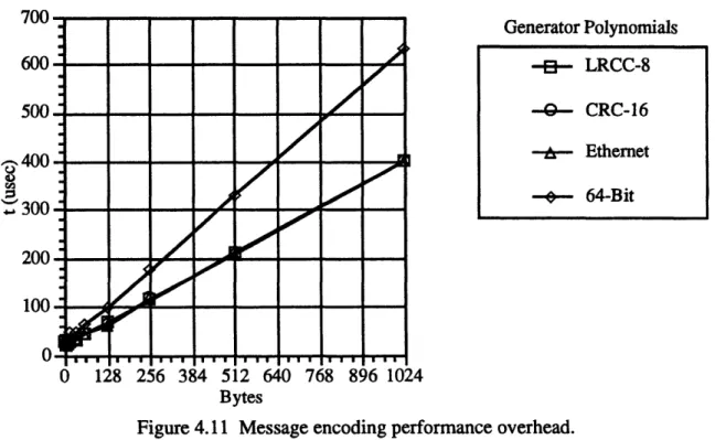
Figure 4.11 Message encoding performance overhead ... 46
Figure 5.1 Connectivity requirement ... 50
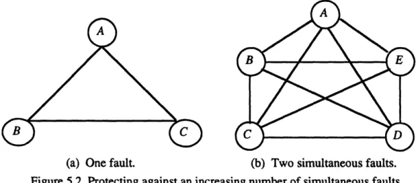
Figure 5.2 Protecting against an increasing number of simultaneous faults ... 51
Figure 5.3 Message passing using SM(m) ... 52
Figure 5.4 Using nested signatures to isolate faults ... 55
Figure 5.5 Generating nested signatures ... 57
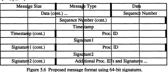
Figure 5.6 Proposed message format using 64-bit signatures ... 58
Figure 5.7 "Two-faced" clock with incorrect sequence number record keeping ... 59
Figure 5.8 Interactive consistency exchange buffers ... 61
Figure 5.9 From_a message passing and buffer space at end of rounds ... 62
Figure 5.10 From_all message passing and buffer space at end of rounds ... 66
Figure 5.11 Nested signature performance overhead ... 71
Figure 5.12 Broadcast message passing performance overhead ... 71
Figure 6.1 Minimal configuration fulfilling interactive consistency requirements ... 74
Figure 6.2 Examples of incorrect and correct choice functions ... 74
Figure 6.3 Example of a voting protocol ... 76
Figure 6.4 Voting exchange buffers ... 80
Figure 6.5 Voting message passing and buffer space at end of round ... 81
Figure 6.6 Comparison of voting performance overheads ... 85
Figure 7.1 An abstract picture of clock synchronization ... 88
Figure 7.2 Synchronization fault with authentication ... 92
Figure 7.4 Application and required synchronization frames ... 97
Figure 7.5 Message transmission delays and message delay error. ... 98
Figure 7.6 Comparing the different time references. ... 101
Figure 7.7. Virtual time- vs. task execution-based synchronizations ... 103
Figure 8.1 Layering scheme for the proposed architecture ... 106
LIST OF TABLES
Table 3.1 Theoretical requirements forf-Byzantine resilience ... 23
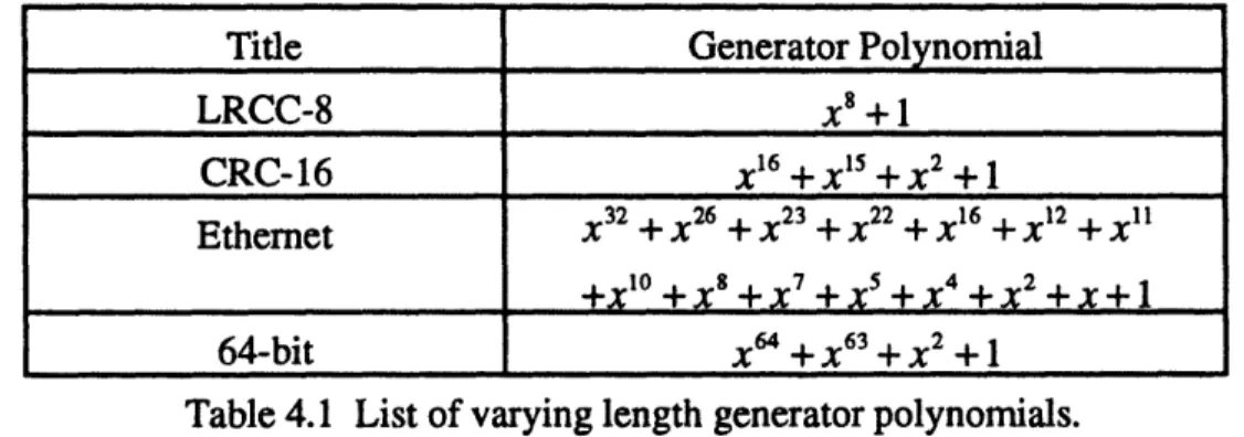
Table 4.1 List of varying length generator polynomials ... 45
Table 4.2 Implementation properties of CRC initialization ... 45
Table 4.3 Signing/authenticating performance overhead ... 47
Table 6.1 Interactive consistency vs. voting requirements ... 75
Table 7.1 Comparison of convergence functions [Sch87] ... 93
Table A. 1 List of 64-bit modular inverses used in the implementation ... 111
Table A.2 List of other 64-bit modular inverses ... 112
1. Introduction
1.1. Problem Statement
Mission- and life-critical computing systems are demanding increasing levels of reliability. Current allowable failure probabilities range from 10-4 to 10-6 per hour for mission-critical functions and 10-6 to 10-10 per hour for vehicle-critical and crew-safety functions [HL91]. As a result, the traditional method of designing fault-tolerant
processors using a failure modes and effects analysis (FMEA)-based approach has become extremely costly and time-consuming. To guarantee a certain reliability, these systems not only have to show that the probability of a modeled fault occurring is within parameters, but that the chances of an unpredicted fault is also within bounds. An alternative to this technique avoids making a priori assumptions by allowing faults to act in any manner, up to and including malicious and intelligent behavior. Such a system is called "Byzantine resilient," or capable of withstanding Byzantine faults.
Making an architecture Byzantine resilient provides the ability to mask, or continue operation in the presence of, a specific number of faults. The requirements for such fault-masking involve lower bounds based on the number of faults that the designer wishes to protect against. These bounds determine how many processors must be in the system, what the connectivity between the processors must be, and how many times information must be exchanged between processors. An additional requirement that the individual processors be synchronized to within a known skew prevents one processor from deadlocking the system.
Theoretically, af-Byzantine resilient processor which uses an authenticated protocol (i.e., a protocol where messages are signed with digital signatures to allow the detection of certain faults) has definite advantages over those using unauthenticated protocols. These advantages include a decrease by a factor off in the number of processors, the ability to eliminate of voting of entire messages, and a reduction in required message passing and connectivity. The problem is that these advantages do not necessarily translate into a faster, more efficient architecture when implemented. For example, the increased message length due to signatures could seriously affect latency.
Before a processor providing Byzantine resilience using authentication can be designed and implemented, a study is required to investigate the fault-tolerance issues involved in such a computer architecture, to identify and propose solutions for the main functional blocks needed for implementation, and then to implement sections of the architecture to make decisions based on performance issues and to pinpoint areas needing optimization.
1.2. Objective
There are certain practical issues relating to an architecture's Byzantine resilience and multiprocessing which must be resolved: authentication, interactive consistency, voting, fault-tolerant clock synchronization, and the performance of the proposed
architecture. The proposed architecture is centered around a method of signing messages that provides unforgeable signatures which (1) allow detection of any alteration of the message's contents and (2) can be authenticated by any processor in the system. A cryptographic scheme must be chosen to balance the needs of data integrity against performance. Interactive consistency (a process where all nonfaulty processors agree on a vector, y) between the processors must be provided through a fault-tolerant distributed decision algorithm. A voting protocol is needed to check for faults by exchanging
congruent information, that is, data which are the same on all nonfaulty processors. Fault tolerance issues require that the clocks on all nonfaulty processors be synchronized to within some known skew in order to guarantee termination of tasks [FLP83]. Finally, performance issues involved in all of the proposed solutions (i.e., added latency due to message signatures) must be taken into account. The objective of this thesis is to identify and evaluate solutions to these problems.
1.3. General Approach
The first step in any computer design is to examine the motivations behind developing the architecture. These motivations heavily influence any decisions which must be made and therefore need to be thoroughly understood. Their relative importance to each other must be clearly stated in order to settle any tradeoffs which appear during the design process. Most importantly, any conflicts must be resolved before any other work is done.
Once the motivations behind designing the system are understood, the architecture needs to be split into its functionality blocks (i.e., interactive consistency,
synchronization, etc.). These functionality blocks provide abstract layers which are the interface between the user and the system's hardware. The requirements for each block must be outlined and then a thorough study of the theoretical work in each specific area done. Once a solid foundation has been achieved, a selection process is performed in order to choose algorithms that not only fit the problem being studied, but are also
realistically implementable. The tradeoffs involved in actually implementing the protocols must then be examined in the context of the rest of the system.
Once the individual blocks are designed, an implementation needs to be done to get a more accurate picture of how the architecture performs. Any design tradeoffs that remain within the architecture can be tested to show the performance advantages and disadvantages of each side of the issue This information can be combined with the individual capabilities of each choice to make a final decision. These measurements can then be compared to other Byzantine resilient processors to give a clear idea of what will be gained and what will be lost if the architecture is later consummated.
2. Motivation
2.1. Overview
The Charles Stark Draper Laboratory has been heavily involved in fault-tolerant computing since digital computers first began to become a vital part of guidance, navigation, and control systems. Starting with the Fault-Tolerant Multi-Processor (FTMP), a project sponsored by NASA in parallel with the software-implemented fault-tolerance (SIFT) program, Draper Laboratory began investigating the issues associated with designing fault-tolerant computers to be used for controlling aircraft [HLS87]. A number of generations of processors have followed the FTMP in providing highly survivable systems. These systems were specially developed to provide extremely reliable, real-time embedded capability for critical operations. The architecture proposed
in this thesis encompasses the next step in this progression.
This processor plans to provide the same high level of fault-tolerance and to support the same type of applications as its predecessors. The main difference comes from the use of authentication and the corresponding decrease in the requirements
necessary to provide the required reliability. These savings have been extended into an attempt to cut the costs involved in such a specialized piece of equipment without seriously impacting performance.
2.2. Fault-Tolerance Requirements
The traditional method of designing fault-tolerant systems is to use a failure-mode and effects analysis (FMEA)-based approach. This technique analyzes likely failure modes of the system, predicts the probability of their occurring, and then designs the system to protect against those that are found to be likely to appear. The reliability of such a system is based on the probability of an unanticipated fault occurring. With reliability requirements of life- and mission-critical systems falling to less than 10- 9 per hour, this approach has become both extremely expensive and unrealistic. A way of mathematically proving that a system will continue to operate in the presence of faults is needed.
The need for fault-masking protocols was reaffirmed when certain strange and totally unanticipated failure modes were observed. At least one in-flight failure of a triplex digital computer system was traced to an apparently Byzantine fault and the lack of architectural safeguards against such faults [MG78]. Also in circuit-switched network
studies at Draper, a failure mode was observed in which a faulty node responded to commands addressed to any node [HL91]. Finally, a failed processor sending different information to other processors was observed in the SIFT computer [Pal87]. Such faults occurring in a system which is not designed to withstand them would be catastrophic.
The realization that designers could never protect against all possible failure modes resulted in what has become known as the Byzantine General Problem. The terminology and the theoretical foundation for work in this area comes from a paper by Lamport, Shostak, and Pease [LSP82] where they state:
Reliable computer systems must handle malfunctioning components that give conflicting information to different parts of the system. This situation can be expressed abstractly in terms of a group of generals of the Byzantine army camped with their troops around an enemy city. Communicating only by
messenger, the generals must agree upon a common battle plan. However, one or more of them may be traitors who will try to confuse the others. The problem is to find an algorithm to ensure that the loyal generals will reach agreement.
The generals correspond to processors while the messengers represent interprocessor links. [LSP82] and papers that followed [Dol83, DS83, DDS84] provide a set of requirements (lower bounds and protocols) which if obeyed make a system f-Byzantine resilient, guaranteeing correct operation in the presence off arbitrary faults.
These requirements are necessary to guarantee the correct dissemination of single-source information, vital for the operation of the overall system. Internal tasks such as synchronization depend on the assumption that a certain set of the collected information is accurate. Information taken from external interfaces comes from redundant sources to prevent a single point of failure and must be utilized by the system. Figure 2.1 illustrates a common example of information processing used for controlling an aircraft. Redundant sensors A, B, and C deliver data such as wind speed and altitude to each of the processors in the system. The processors then use a fault-tolerant exchange protocol to distribute the input information so that each nonfaulty processor now has a correct set of the sensor readings. Each processor performs any required filtering and computations before performing a second fault-tolerant exchange to decide which command to deliver to the redundant system effectors. If the guidelines are followed, there is no way forf or fewer faults to corrupt the flow of information between the remaining nonfaulty processors.
Fault-Tolerant Input Exchange Sensor A Sensor B Sensor C Fault-Tolerant Computation _ __o-" / Fault-Tolerant Output Exchange EffectorA EffectorB Effector C
Figure 2.1 Information processing in a Byzantine resilient system.
2.3. Cost and Performance Goals
The previous Byzantine resilient systems at Draper have mainly been designed as hard real-time embedded systems to be used on aerospace vehicles. Hard real-time systems are characterized by the presence of hard deadlines where failure to meet a deadline must be considered a system fault [SAE91]. This requirement places very specific performance demands on the system. These demands must in turn be balanced with the need to keep the system small so that it can be placed in the tight space of the vehicle. Since the systems were built mostly for military or space projects, a premium
was placed on achieving high-throughput combined with fault-tolerance instead of reducing costs. This need for high performance resulted in architectures which
implemented as much functionality as possible in hardware, often times proprietary, and were highly optimized for a specific platform.
In this generation of processor, an attempt is being made to lower the cost of our system and thus make it available to a wider customer base. Authentication is used in the architecture because of its ability to lower the requirements in the amount of hardware needed to make the system Byzantine resilient. For example, the number of processors needed to protect against one Byzantine fault drops from four to three. These changes are discussed in more detail in Chapters 3 and 5, but reducing the number of processors by
even one is a huge improvement. A secondary goal is to build the system with multi-platform capability. If the system runs on a variety of different processors, the user can
then choose a package depending on the amount of money they are willing to spend and the level of performance desired.
These goals place a number of constraints on the structure of our architecture. Any use of specialized and/or proprietary equipment must be avoided due to both their high cost and compatibility problems. In fact, as much as possible of the system's functionality should be implemented in software. If the individual protocols needed to implement the required fault-tolerance are written in a high-level programming language and placed as layers between the user and hardware, porting the system from platform to platform is greatly simplified. One of the important purposes behind this thesis is to examine the effect that these policies have on the overall system.
Each protocol has a number of different design options which must be examined to find the one which fits the best with these goals. A great deal of throughput is often sacrificed when functions are done by software instead of hardware. Different solutions to problems need to be tested to determine which helps the system's performance the most. Once all of the design issues are resolved, the resulting architecture must be studied to find the sections which should be optimized, either by writing processor-specific assembly code or adding additional hardware.
3. Fundamental Building Blocks
3.1. Overview
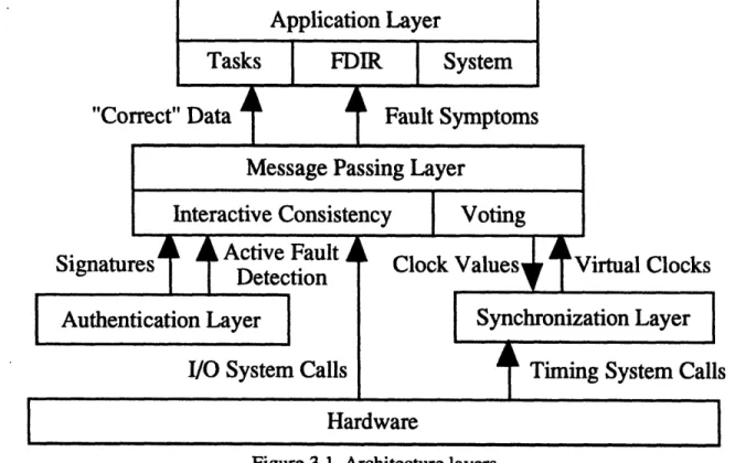
The proposed architecture has been designed using the concept of layers. The layers serve as an interface between the user and hardware which provide the desired Byzantine resilience. The use of software to implement the needed functionality removes any dependence on specific hardware to build the system. The only contact that the layers have with the hardware is through system calls which manage the reading of physical clocks and I/O for sending and receiving messages. Each layer consists of one or two protocols which are responsible for sending all necessary information to the user. Figure 3.1 provides an abstract view of how these layers fit together.
Figure 3.1 Architecture layers.
The layer placed directly beneath the Application Layer is responsible for all communications between the individual processors. Two protocols are implemented in this Message Passing Layer. The interactive consistency protocol oversees the exchanges
used to distribute single-source information in a manner which masks possible faults. At the end of an interactive consistency exchange, all nonfaulty processors have a
The voting protocol is used to gather and compare sets of data in order to reach a group consensus value which is the same on all nonfaulty processors. This layer depends on
system calls to hardware to process messages and information garnered from the lower layers.
There are two layers found below the Message Passing Layer. The first is the Authentication Layer which provides the digital signatures to be appended to the end of all messages. The authentication protocol within this layer directs the signing and verifying of messages and is responsible for detecting active faults which affect the contents of a message. The second layer is the Synchronization Layer which provides virtual clocks, built on top of the system's hardware clocks, which are synchronized to within a known skew. The clock synchronization protocol found in this layer is
responsible for starting synchronization intervals and adjusting the system's virtual clocks to keep them synchronized. The protocol uses the Message Passing Layer to read the virtual clocks on other processors and system calls to read a processor's own hardware
clock while fulfilling its functions.
The protocols found within these layers are the building blocks which form this architecture. Each one must be completely specified and designed before any
implementation work can begin. The rest of the sections in this chapter give a general outline of each protocol. Chapters 4, 5, 6, and 7 then give an in-depth description of each problem and the final proposed solutions for each.
3.2. Authentication
Authentication forms the foundation upon which the rest of the architecture is built. All of the other protocols are affected in some way by its presence. The
restrictions on the types of undetected faults which authentication provides allow a reduction in the requirements necessary for interactive consistency. The presence of signatures provides a new method of achieving group consensus. However, the need for all data to be signed before it can be sent to other processors constrains the options available for synchronization. The authentication protocol must therefore be the first one to be designed.
Authenticated protocols were developed when the need for secure computer communications first became apparent. Users realized that they required an efficient method of verifying the identity of those sending them messages. Protocols were
designed to provide a wide-range of services from the establishment of secure interactive communications between principals on different machines to authenticated one-way
communications for mail systems and signed communications where the origin and contents of a message could be authenticated by a third party [NS78]. Uses for this last function were seen from the very beginning of work in the field of Byzantine resilience.
The first Byzantine resilient algorithm using authentication appeared in [LSP82]. The authors realized that the ability to append a signature to the end of all messages and allow the receiver to verify the original sender and contents of the message made certain powerful assumptions about faults possible. Faults can be classified as either passive or active. Passive faults have no effect on the contents of the message and usually involve messages being delayed or blocked. Active faults are directly connected to the contents of the message. For example, a processor trying to masquerade as another processor or a noisy link corrupting messages are active faults. The use of authentication allows the designer to assume that all active faults are detected through checking the signatures and therefore do not need to be masked by a separate message passing protocol (i. e., an interactive consistency protocol). This assumption makes a drastic reduction in the complexity of Byzantine resilient systems possible.
Unauthenticated Protocols Authenticated Protocols
Number of processors [LSP821 3f + 1 2f + 1
Connectivity [Dol83] 2f + 1 f + 1
Communication Rounds [DS83] f + 1 f + 1
Messages [DS83] O(n') o(nf)
Voting Required [LSP82, DS83] Yes No
Synchronization [DDS84] Yes Yes
Table 3.1 Theoretical requirements forf-Byzantine resilience. The use of digital signatures allows a reduction in both the hardware and communications necessary to provide Byzantine resilience. Table 3.1 compares the theoretical requirements for unauthenticated and authenticated protocols as a function of f, the number of faults which the system protects against. The number of processors and
the connectivity between them is reduced by a factor off. The same amount of communication rounds are needed, but the number of messages which are sent within each round has fallen. The final difference is that the processors no longer have to perform a vote on the entire message since the signatures provide an encoded version which can be compared instead. The effect these changes have on a Byzantine resilient architecture is the main motivation behind this thesis.
3.3. Interactive Consistency
An architecture's claim of Byzantine resilience depends on the protocol used to provide interactive consistency. This protocol is utilized whenever data appears on only one processor. Such single-source information must by exchanged using fault-tolerant message passing techniques to provide congruent copies, or data which is the same, on all nonfaulty processors. Common examples of single-source data are a reading from one redundant sensor or the value of a processor's local clock. A more exact definition of interactive consistency is a set of processors agreeing on a piece of information
originating from a single source in such a way that the following Byzantine Agreement conditions are fulfilled:
Agreement: If any nonfaulty processor decides value V, then all nonfaulty processors decide V.
Validity: If a nonfaulty processor starts with an initial value V, then V is the only allowable decision by all other nonfaulty processors.
Termination: All nonfaulty processors decide on a value V within a known amount of time.
The value V which is agreed upon by all nonfaulty processors is considered to be "consistent." If the processors perform the same operation on this consistent data, they are considered to be operating "congruently."
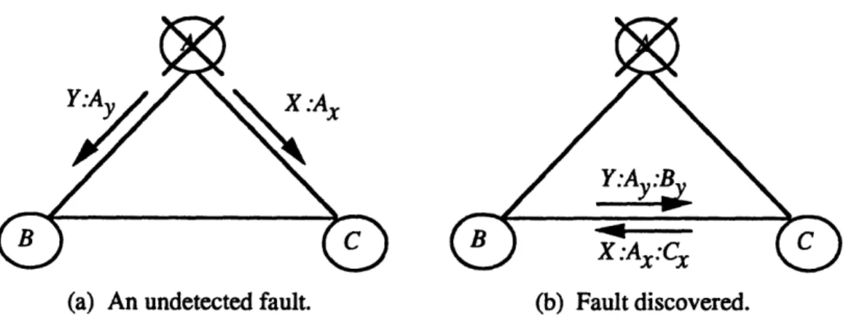
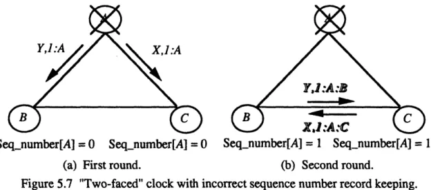
Obtaining interactive consistency in the absence of faults is a trivial problem since the sender simply has to transmit its data to the other processors. Once Byzantine faults are introduced, the process becomes much more complicated. Figure 3.2 illustrates our problem in the presence of a commonly discussed Byzantine fault, a "two-faced" clock.
In this scenario, a faulty processor sends a different value to each of the other processors. In Figure 3.2(a), faulty processor A sends signed messages containing conflicting data to
the nonfaulty processors B and C. Authentication does not help to discover this fault since the two varying messages correspond to their signatures. If the protocol were to stop at this point, B and C have no way of realizing that they have inconsistent, or differing, information. The second round of message passing shown in Figure 3.1 (b) is needed between B and C in order to discover the problem. After the second round, B and C each have a set of two different messages which have verified as originating from A and therefore, upon noticing a disagreement, each chooses the same default value.
X.Ax
(a) An undetected fault. (b) Fault discovered.
Figure 3.2 Detecting a "two-faced" clock.
A protocol must be designed to implement the required message passing and provide interactive consistency in the presence of Byzantine faults. It is vital for the architecture to guarantee that after an exchange, the information on nonfaulty processors is consistent. If a fault were to occur that caused conflicting data to be accepted on nonfaulty processors, the actions of the processors could diverge, causing a failure of the entire system.
3.4. Voting
The second protocol in the Message Passing Layer is known as the voting protocol. This protocol is responsible for calculating a group consensus value which is guaranteed to be the same on all nonfaulty processors. Periodic exchanges are performed when processors are expected to be acting congruently, or performing the same
operations on identical data. The goal of these exchanges is to gather a set of values containing an element from each processor to be used in calculating the group consensus value. These voting exchanges are employed mainly by Fault, Detection, Isolation, and Recovery (FDIR) tasks to detect faults.
Voting exchanges result in a set of data with elements from each processor and a group consensus value. Since the processors are expected to be acting on congruent information, the data from nonfaulty processors should be the same as the group
consensus value. FDIR tasks generate fault symptoms by comparing the group consensus value to every element in the data set and marking every processor which provided noncongruent data as faulty. Voting exchanges are also used just before an output to filter any computational faults.
The voting protocol is designed after the interactive consistency protocol because it is constrained by interactive consistency requirements. The fault tolerance claims of the entire architecture rest on the correctness of the interactive consistency protocol so the voting protocol must be structured to fit with the other protocol. Also, any requirements added by the new protocol are not allowed to come into conflict with the interactive consistency requirements. The design of the voting protocol must be done to complement the interactive consistency protocol.
3.5. Synchronization
One of the most important and complicated requirements for reliable real time systems is the need for synchronized processors. In fact, Fischer, Lynch, and Paterson show in [FLP83] that it is impossible to make an asynchronous system resilient against even one fault. If one processor stops sending messages, the rest of the system could deadlock. The other processors have no way of deciding whether the faulty processor has
failed or is simply far behind the rest. The normal solution to this problem of using time-outs implies, by it very presence, some form of synchronization.
Other technical problems were discovered in the advanced fighter technology integration (AFTI) F-16 program [Mac88]. The digital flight control system (DFCS) was designed so that the three computers in the triply redundant system were not
synchronized. The designers believed that computer synchronization introduced a single-point failure caused by electromagnetic interference (EMI) and lightning. The AFTI F- 16 program found that the asynchronous aspect of the architecture introduced errors in the inputs due to time-skewed sampling by the different processors. An even more serious problem became apparent in the verification process. The system became untestable in that testing for each of the possible time relationships between individual processors was impossible. This attempt at asynchronous operations only served to reinforce the need for synchronization.
Synchronization requires that each nonfaulty processor have some idea of "real" time within a known skew of all other nonfaulty processors. A clock falling outside of this skew bound is considered a processor fault. Fault containment considerations make it necessary for each processor to have its own local independent clock. Using one global clock makes synchronizing the processors trivial, but also introduces a single-point failure. The problem is that no matter how accurate the individual clocks are, they still tend to drift apart over time. Clock synchronization protocols are used to correct for this drift.
Clock synchronization protocols implement virtual clocks in a way which should be invisible to the user. The method used to synchronize the clocks must be chosen based on the overall characteristics of the architecture. Another important consideration is the amount of overhead introduced by the protocol. In the SIFT computer, twelve out of sixty-six slots in each major frame were dedicated to clock synchronization and
redundancy management, an overhead of 18% [PB86]. A protocol which avoids a large amount of overhead when the system is busy is preferred.
4. Authentication 4.1. Overview
The Authentication Layer provides a service upon which the rest of the
architecture rests. Its authentication protocol uses digital signaturing techniques to allow a recipient to verify the authenticity of a received message with high probability. These signatures are used by the protocol to isolate the many types of active faults which can occur within the system. There are requirements, both theoretical and practical, which must be fulfilled by these signatures. The technique used to calculate the signatures must
also be flexible and comprehensive enough to detect events varying from messages arriving late and outside real-time constraints to an intermediate processor repeatedly transmitting a message. On the other hand, latency is added to message processing every time a message is signed and verified, adversely affecting performance. The signaturing function must therefore be chosen carefully to meet all requirements while accounting for these problems.
Authentication protocols are defined by the type of signaturing scheme which is employed. The most common types of protocols are based on methods using key-pairs to sign and then verify a message. These protocols are classified into two groups, private-key authentication and public-private-key authentication. In private-private-key authentication, a sender generates signatures using a private-key; any receiver which wants to verify the
message's authenticity must also have access to the private key. On the other hand, public-key authentication makes use of key-pairs where the sender signs the message using a private key, while the receiver applies a public key related to the private key to verify authenticity. Designing the final authentication protocol for this thesis involves analyzing the advantages and disadvantages of these two protocol types, selecting the best for this architecture, and incorporating a signaturing scheme which fulfills all of the requirements mentioned in the next section. Finally, the machinery necessary for signing and verifying messages needs to be build in order to investigate the performance issues involved in authentication.
4.2. Authentication Requirements
Before work on designing the authentication protocol can begin, the many requirements which must be met by the signatures need to be examined in detail. The
individual signatures determines the reliability of the entire system, since the architecture may not protect against undetected active faults which have defeated the authentication protocol. Such an undetected active fault could cause a catastrophic system failure. At the same time, attempts to make the scheme more robust often result in poorer
performance. There are two main issues which need to be investigated with these factors in mind. The architecture's claim of being Byzantine resilient depends heavily on
theoretical assumptions about signatures. Decisions about how strictly these assumption will be upheld must be made. Also, these assumptions need to be translated into
implementation requirements for the signatures.
All Byzantine resilient algorithms using authentication assume the ability to generate signatures such that
Al: A sender's signature cannot be forged by another process. A2: Any alteration of the sender's message can be detected.
A3: The receiver can readily verify the authenticity of a sender's signature-message pair.
These assumptions can never be totally guaranteed in an actual implementation due to the structure of digital signatures. Digital signatures consist of a finite number of bits which can always be generated randomly by a processor. The signaturing scheme must be
optimized to provide the needed amount of security without affecting the rest of the system.
Even though assumption Al cannot be ensured, it is possible to make forging the signature extremely difficult. The probability of a processor forging a sender's signature by random attempts decreases as the number of bits in the signature increases. For example, if we assume that a processor generates messages at the rate of 106 per hour, and a probability of system failure of 10-10 per hour is desired, then the probability of forging a signature needs to be 10-16 per message. The signature would need to consist of at least 53 bits to provide a probability of forgery of 10-16. This is only a lower bound for the number of bits in the signature since this assumes random attempts to forge a
signature. Assuring unforgeability to malicious attempts may require a greater signature length.
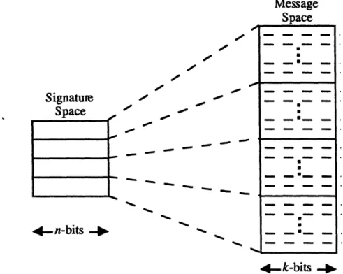
Similarly, assumption A2 cannot be guaranteed with unity probability since the generation of an n-bit signature for a k-bit message, where n<k , implies that there exists a signature which corresponds to at least two messages (and probably even more). Thus, a processor may change the contents of a message with a finite probability that the
changed message's signature is identical to the original message's signature. If we assume that the signaturing scheme uniformly distributes signatures over the message space, that is for all signatures v in the signature space Q, vi is the signature for exactly
2*-" messages, we can estimate the probability that a processor can undetectably corrupt a message, leaving the signature unchanged, to be 2-". Figure 4.1 shows an example of such a distribution. If a 2-bit signature is appended to an 8-bit message, there are only 22, or 4, signatures to represent the 28, or 256, possible messages. If a message is corrupted, there is a 2-2 (14 ) probability that the new message falls into the message
space corresponding to the same signature. To provide a probability of undetectable corruption of 10-16 per message would again necessitate a signature of 53 bits and a
"spectrally white" signaturing scheme.
Message Space Signature
-Space
_
_
--a,_
_ _ - - - -_4. n-bits
-4-k-bits
-I.
Figure 4.1 Evenly distributed signature and message spaces.The security required by signatures is determined by the level of intelligence we are willing to attribute to faults. For many applications, we can assume that faulty processors may exhibit malicious behavior, but not to the extent of a malicious
cryptoanalyst, particularly in cases in which we are using authentication to protect against random hardware failures in fast hard real-time applications. Therefore, our signaturing scheme need not be cryptographically secure but only robust against randomly malicious
a a a m - m mm _ _ _m _ _m _ _ _ U _ . _ro _ _ o _ m _m _m _U _m _ m_ _ : · _ lm _m _mmm l m m _m _ _m _ _ m : m[m _ _*_ m_ ____ _mmm _ __m m m [e _ _ _m _ i
behavior. Due to the malicious nature of some hardware failures we still need to exercise some caution in determining a signaturing scheme.
Considerations other than the security of the signatures must be taken into account in designing a signaturing scheme. Certain information must be provided in all
signatures to vitiate the many different types of active faults. First of all, signatures must be host-specific to prevent one processor from masquerading as another. In the flawed example shown below, processor B pretends to be processor A and sends "A says go", signing it with S. If the signatures are not host-specific, processor C would accept the message as coming from processor A.
Figure 4.2 Undetected fault with a non-host-specific signature.
Host-specific signatures keep a processor from being tricked as to the origin of the message. Replaying the above scenario with host-specific signatures, if B sends the message "A says go" and appends Sb to it, C will realize that the message did not originate from A.
Figure 4.3 Detected fault with a host-specific signature.
Also, signatures must be message-specific in order to prevent an intervening processor from corrupting a message and then appending a correct signature to it. In the
flawed example shown below, processor A sends "A says go" and signs it with Sa. If the signatures are not message-specific, processor B could corrupt the message to "A says stop," append Sa to it, and C would accept the corrupted message as authentic.
Message-specific signatures keep a processor from copying another's signature and appending it to a corrupted message. Replaying the above scenario with message-specific signatures, if B corrupts the message from "A says go" to "A says stop" and attempts to append Sa to it, C will detect that the signature and the message do not match and discard the message.
Figure 4.5 Detected fault with a message-specific signature.
However, even with host- and message-specific signatures, an intermediate processor can still erroneously and undetectably repeat a message-signature pair. In the flawed example shown below, processor A sends "A says go" followed by "A says stop." Processor B can erroneously save the first message and transmit it twice, absorbing the
second message without C being any the wiser, since both messages received by C authenticate.
Figure 4.6 Undetected fault with a non-time-specific signature. To eliminate this possibility, a monotonically increasing sequence number can be attached to each message by the sender. The sequence number introduces a varying message component which ensures that a relaying processor cannot undetectably replay a saved copy of a message. Such replays would be rejected by the receiver because they have identical sequence numbers. Sequence numbers also ensure that, when a source intentionally transmits two identical messages, the signatures will differ because the signature, which is calculated with respect to the message and the sequence number, has a spectrally white dependence on both the message and the sequence number.
A says go, 1,
A says stop, 2
1 A says go, 1, Sa,2
, says go, 1, Sa, 1
Figure 4.7 Detected fault with a time-specific signature. 4.3. Authentication Protocols
Authentication protocols are responsible for the mechanics of signing messages at the sender and verifying their authenticity at the receiver. There are two basic approaches to authentication used by such protocols, private-key authentication and public-key
authentication. Private-key authentication is the traditional type of cryptosystem which has been used for centuries where anyone who wants to verify a message needs to know the key used by the signer. On the other hand, public-key authentication is of more recent origin (at least within this century), first suggested by Diffie and Hellman in [DH76]. Diffie and Hellman proposed using key pairs where one key is utilized to sign the message and the other key is used to verify both the sender and the message itself. There are advantage and disadvantages to both types which need to be weighed before the final protocol can be designed.
4.3.1. Types of Authentication Protocols
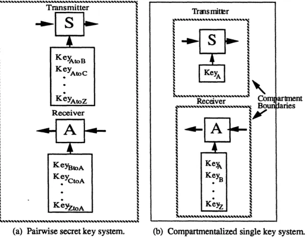
The approach for an authentication protocol implementing private (secret) keys uses a signaturing function, v = Sk (M), which generates a signature v for the message M based upon a key k. Every participant that wishes to authenticate messages from a sender must possess k, the key the sender used to sign the message. A receiver i verifies a message from a sender j by computing Sk (M) using the sender's key and comparing that signature with the signature appended to the message. One problem with private key authentication is that the authentication key must be identical to the key used to sign the message. Hence a receiver which is able to authenticate a message from a sender j is also able to forge outgoing messages with j's signature. Two methods may be used to prevent this scenario from occurring.
The first method is to use pair-wise common keys. Each sender j has a different key for each other node in the system. A receiver i has the key that each sender uses to sign messages sent to i. (See Figure 4.8(a).) Thus in the worst case, a faulty node can
only forge messages to itself. This solution creates a number of key management problems and precludes the ability to broadcast information to all participants without
attaching a separate signature for each potential recipient.
The second method to prevent a receiver from forging a message is to
compartmentalize the receiver from the transmitter (See Figure 4.8(b).). By this, we mean that the designer must insure that no propagation of key information from receiver to transmitter is possible through the use of hardware isolation/protection mechanisms. One method for doing this would be to only allow the transmit key to be set on power-up. Again, this method creates a number of key management problems; however unlike the previous method, it does allow a node to broadcast messages without attaching a separate signature for each potential recipient.
artnent laries
(a) Pairwise secret key system. (b) Compartmentalized single key system.
Figure 4.8 Approaches to private-key authentication.
In public-key cryptosystems each participant i has an encoding function which generates a n-bit representation of the message, M, as well a signing function Di and an authenticating function Ei with the following properties:
Transmitter Receiver '4 '4 '4 '4 '4 '4 '4 '4 '4 '4 '4 '4 '4 '4 '4 '4 '4 '4 Transmitter k, 1~~~~~~~~~~~~~~~~~4 4. N~~~~~~~~~~~~~~~~' k N Receiver
t'4''' ''''vx'x''''4s
ComBouwX
L.4~~~""~~~~~""~~~~~~"`~~~~~""·""4~~~~~~~~%
i
-00 i P P ri
BI: E(Di(M#)) = M#.
B2: Both Ei and Di are easy to compute.
B3: Dicannot not be inferred from knowledge of Ei with any reasonable effort.
The nomenclature for the functions may be confusing, but it comes from the original public-key proposal in [DH76] which envisioned the public keys being used to send (and therefore encode) messages which could only be read (and therefore decoded) by a receiver with the private key. We have renamed the functions to correspond to their uses in our design, but have kept the original symbols. To apply the public-key cryptosystem scheme to a public key authentication system, sender i encodes the message M, such that M, is a n-bit number representative of M,,e,. The spectrally white encoding function
is common knowledge; computation of a CRC over the message is an acceptable algorithm. The sender then uses its private signing function Dion M# to calculate the signature. The receiver uses the authenticating procedure E, which is common knowledge for all i, to verify the message. To be specific, for processor A to send a
message to processor B, the following steps are taken:
1. A computes M# = Encode(M,ext).
2. A computes the signature SA = DA(M#).
3. A sends (Mtext,S,) to B.
4. B computes M# = Encode(Mx,). 5. B strips off SA and computes EA(SA).
6. If EA (SA) = M#, then the message is authentic.
While public-key signature systems do not need secret keys, and broadcasts are possible, they do require the availability of suitable functions Ei and Diwhich possess properties Bl-B3. The public-key authentication method does eliminate the problems associated with key management and allows efficient broadcasts.
4.3.2. Proposed Protocol Design
The decision about which type of authentication protocol to employ needs to be made based on how authentication will be used by the system. This protocol is placed in a low level layer beneath the message passing protocols. It is necessary for the
processors to be able to broadcast message to the other processors without incurring performance hits. Also, remember one of the goals behind this architecture is to
implement as much as possible, if not all, of the functionality in software in order to cut costs. Avoiding problems with key management or the need for hardware
isolation/protection mechanisms is therefore desired. These factors made public-key authentication the obvious choice for this system.
The final proposed protocol is a public-key cryptosystem based on Cyclic Redundancy Codes (CRC's) and modular inverses. CRC's provide a spectrally white means of encoding the message which is relatively simple to either code in software or build in hardware. From the evaluation discussed previously in Section 4.2, the number of bits necessary to make the probability of forgery adequate for our applications
necessitates a CRC of greater than 53 bits. For ease of implementation, this would require a CRC length of 64 bits (the closest multiple of a byte to 53). The signing and authenticating functions use modular inverse keys which are two numbers, P and P- (P inverse), for which P P-' mod 2" = 1 is true where 2" is a very large number. P acts as the private signature key while P-l is the public signature key. Several examples of modular inverses are:
13.5mod2 5= 1 1033 569mod2 1n = 1
9294586028090703467 350969587744990515 mod 2 = 1.
The signing function, Di(M#), is P M# mod2" while the authenticating function, Ei(Si) is Si P-' mod2" where 2" is the number of possible signature configurations (and n is the number of bits in the signature) and M# is a n-bit representation of the message. B 1 from the previous section is fulfilled since
Ei(Di(M.)) = (P M# mod 2" ). p-i mod 2" = M#, (P. P-' mod 2") = M#
(Please note that (x mod 2")mod 2" = xmod 2").
B2 is also upheld because both Ei and D, contain only n-bit multiplication and modulus functions. The steps necessary to infer Di from E, are discussed in the next section, but do require a large amount of effort, satisfying B3.
The protocol uses a combination of these functions to provide its signatures and then authenticate its messages. When processor A sends a message to processor B, the following steps are taken:
1. A computes M# = CRC(Mext).
2. A computes the signature SA = DA (M#) = P M# mod 2'.
3. A sends (M,e,, SA) to B.
4. B computes M# = CRC(Mext).
5. B strips off SA and computes EA(SA) = SA P-' mod 2.
6. If EA (SA) = M#, then the message is authentic.
4.4. Key Generation
The signing function Di and the authenticating function Eirequire a pair of modular inverse keys, P and P-', for each processor in the system. P is used by Di as the private key and is assigned to only one processor. P-' acts as the public key for Ei and a
table of all public keys is maintained on every processor. The only key management required by these pairs is at compilation time when the private key initialization routines for each individual processor are placed in separate files to ensure isolation.
The key pairs are generated using an extended version of Euclid's algorithm found in [Knu69]. Euclid's algorithm is a famous method for finding the greatest common denominator (gcd) of two numbers, u and v. Knuth extended it to calculate two more integers, u' and v', such that
u-u'+v v'= gcd(u,v),
(4.1)
at the same time gcd(u,v) is being found. In order to use this algorithm, we note that if
P P-'mod2 n =1 (4.2)
(the definition of modular inverses), then by the definition of the mod function,
P P-' = 2 v' + 1, or (4.3)
p. p-
1+ 2
nv'= 1
(4.4)
where v' is some constant. Therefore if 2" is substituted for v and a prospective n-bit private key is chosen at random for u, Knuth's algorithm solves
If gcd(P,2") • 1, then we know that P is not co-prime with respect to 2" and must try another key. Also, we must discard P-' if it is negative. Otherwise, we may use the key pair, P and P-'. Appendix A contains a list of 64-bit modular inverses generated with this technique.
4.5. Cyclic Redundancy Codes (CRC's)
Cyclic Redundancy Codes, or CRC's, provide the encoding function which is a vital part of our public-key authentication protocol. Encoding functions are responsible for calculating a message-specific sequence of bits which are spectrally white and can be
used to detect errors within the actual message. CRC's are a fast and efficient method which are well known for their ease of implementation, both in hardware and software. While not cryptographically secure, the probability of a faulty process randomly forging the correct signature decreases as the CRC length increases, at a rate of 2-n for a n-bit CRC.
CRC's come originally from finite field theory. Sequences of bits are defined as binary polynomials, where each bit represents a coefficient. For example, the five-bit sequence, 10101, would be associated with the fourth order polynomial,
r(x) = 1+
0
.x + 1 x 2+ O .X3+ 1 .X4 = 1+ x 2+ X4. When a message is represented by such a polynomial, the CRC of the message is defined as the remainder of the modulo-two division of the message polynomial by a particular CRC generator polynomial [Gal90]. Figure 4.9 shows an example of how a CRC is generated. The CRC-16 generator polynomial, g(x) = 1 + x2+ x15+ x16, is used to encode the message 101011. The remainder of the modulo-two division, s(x), is 0111110100000000 which becomes the CRC. xS x2+ x x16+x1 5++2 1 [ x2 1+x2 0+ +x18 ++x1 6x21 + x20 +
+ x7+ x
5 X1 8 + X16 + X7 + X5 x1 8 +x1 7 +x4 +x x1 7+x1 6 + + X5 + 4 +x2x
17+x
16+
x
3+
x
x7+ x5 +x4+ x3+ x2+x S(X)= x7+x5+ x4+x3+x2+xThe following sections are a condensed overview of the CRC techniques used for this protocol. If the reader wishes a more in-depth look into the subject, an article by T. V. Ramabadran and S. S. Gaitonde, titled "A Tutorial on CRC Computations," [RG88] is highly recommended. The most important component in implementing CRC's is the generator polynomial since this polynomial solely determines the error detection properties of CRC's. A detailed explanation of these capabilities and how a 64-bit generator polynomial was derived is found below. This is followed by a description of possible implementation techniques.
4.5.1. Error Detection and Generator Polynomials
The error detection capability of a CRC is controlled by the choice of generator polynomial. The issues involved can be better understood if a corrupted message is represented by the (n + k)" order polynomial, r(x) = v(x) + e(x), where v(x) is the original message of k bits of data with a n-bit signature and e(x) contains the bits in error (e(x) = 0, if the message is uncorrupted). The message is examined for errors by
dividing r(x) by the generator polynomial, g(x), and checking for a zero remainder. The only way errors can go undetected is if the error polynomial, e(x), is also divisible by g(x).
Generator polynomials can be specifically tailored to detect certain kinds of errors. Consider a single error pattern represented by e(x) = x' for some i,
0 < i < n + k -1. If g(x) has more than one nonzero term, it does not divide e(x) evenly and therefore detects all single bit errors. More errors can be detected by using a
generator with (1 + x) as a factor. The resultant CRC's will then also have (1 + x) as a factor which always leads to an even number of terms. If g(x) and v(x) have even parity,
all odd number errors are detected. Now, consider a double error pattern
e(x) = x' + x = x(l + xi-') for some i, O i n + k - 2 andj, i +1 < j < n+ k -1. If g(x)
does not have x as a factor and if it does not evenly divide [1 + xi-'] for 1 < j- i < n + k -1, we can detect all double errors.
Another class of important errors is known as burst errors. A burst error of length b is any error pattern for which the number of bits between the first and last error is b. Let the generator polynomial be of the form g(x) = 1 + g1x+...+gn_x" -1 + xnwhere the
coefficients g,g 2,...,g,, can be either 0 or 1. In other words, g(x) has a degree of n and
is not divisible by x. Any burst error of length n or less can be represented as
can be either 0 or 1. Such a polynomial is not evenly divisible by g(x), and therefore a burst of n bits can be detected. Now consider a burst error of length (n + 1) represented by e(x) = x(1 + elx+...+en_lx,_l+ ex"). Of the 2-' possible error patterns of this form, only one, e(x) = x'g(x), is undetectable. Therefore, the probability of an undetected burst error of length (n + 1)is only 2- n-1) . A similar analysis finds that the fraction of
undetected burst errors of length greater than (n + 1) is 2 - .
The above description covers only one of the many capabilities that CRC's can provide. Generator polynomials can also be chosen to allow certain errors to actually be corrected. The problem is that deriving these error-correcting codes becomes very complicated and time-consuming when expanded to a large number of bits. CRC's normally do not go beyond 32 bits (16 bits is the most common length). In order to test the viability of using 64-bit signatures for the reliability reasons mentioned in Section 4.3.2, a 64-bit generator polynomial needs to be derived. Since the only purpose for CRC's in this proposed architecture is to detect errors and thus active faults, determining the generator polynomial concentrated only on error detection properties. The optimal structure of such a n-bit generator polynomial is
s(x)
=(x + 1)(1
+pix+...+pn_x
-),
(4.6)
where the (1 + pIx+...+p_, x-' ) term is a primitive polynomial. A polynomial of degree m is primhitive if and only if it divides Xn -1 for no n less than q - 1 and is an
irreducible polynomial in that it is not divisible by any polynomial of degree less than m but is greater than zero [PW72]. The (x + 1) term allows the polynomial to detect all odd number errors while the (n - 1)"' order primitive polynomial increases the size of
messages for which double errors can be detected. E. J. Watson in [Wat62] compiled a list of primitive polynomials of degree n, 1 < n < 100. The primitive polynomial of degree 63 multiplied by (x + 1) gives the following generator polynomial:
s(x) = (x + 1)(1 + X63) = 1 + x2 + X6 3 + X64. (4.7)
4.52. CRC Implementation Techniques
One of the main advantages of using CRC's to encode messages is the ease of implementing the function. Traditionally, CRC's have been done in hardware using a
found handling the message on a byte- or even word-level to be easier and faster. This section gives a simplistic description of how to compute CRC's in hardware. A much more in-depth look into the issues involved in hardware implementation can be found in [Gal90] or [Lee81]. Software CRC algorithms are then covered in more detail since the proposed architecture involves one of these choices.
Generating CRC's in hardware can be done using very basic, low-level circuitry. The computation of CRC's involves the modulo-two division of the message by a generator polynomial in order to calculate the remainder. The hardware equivalent of a modulo-two division is a linear feedback shift register (LFSR). Figure 4.10 shows the LFSR circuit for the CRC-16 generator polynomial. To encode the message, the circuit is first initialized with a seed value, usually all zeros or ones for error detection purposes. The message is then fed into the register from the right, bit by bit. The bits remaining in
the register when the message has gone completely through are the CRC. Decoding operates in the same manner, with the message and appended CRC being entered into the register. If the remainder is zero, no errors have occurred. The biggest advantage of using hardware for calculating CRC's is in performance. Messages can be encoded by a shift register "on-the-fly", or in parallel with other processing, causing little extra delay. The problem is that specific hardware dedicated to generating CRC's goes against our design and cost goals of providing a software-based architecture.
g(x) =16 +X15 + 2 + Message for encoding
Message + CRC for decoding Figure 4.10 LFSR circuit for the CRC-16 generator polynomial.
The technique used by a LFSR to process the message bit by bit is easily performed in software. The problem is that the sequential nature of software prevents generating the CRC with computation on-the-fly. A delay is present, adding to performance overhead, whenever a message is signed and verified. Even worse, this delay increases as the size of the message grows. This latency has caused software
algorithms to move away from processing data bit by bit to handling it as bytes or even words. Generating CRC's in larger blocks speeds up performance by decreasing the number of times CRC operations are needed.
Using bytes and words instead of bits removes a number of unnecessary steps in finding a CRC, but the calculations that are left still take time. A faster alternative is to precompute the values for different seeds and place them into a CRC lookup table. The largest timing overhead is therefore moved to a one-time delay during initialization.
Once the table values have been computed, the CRC for a message is calculated using constant size blocks with the following steps:
1. Initialize a CRC register the size of the desired digital signature to all zeros.
2. EXOR the input block with the value in the register.
3. Shift the CRC register once to the right for each bit in the input block. 4. Look up the value corresponding to the block in the CRC register and
EXOR the CRC register with it.
5. Repeat steps 2 to 4 until the end of the message is reached.
This technique requires only shifts, a table lookup, and two EXOR's for each block of data.
The different options for using CRC lookup tables balance performance requirements against storage capabilities. The number of entries in the lookup table depends on the block size used by the algorithm, requiring 2' entries for a e-bit block. A bytewise table algorithm requires twice as many lookups as an algorithm using short
words (16 bits), but only needs 256 (28) entries versus 65,535 (216) entries. If memory is a definite restriction, a reduced lookup table can be used. The reduced lookup table contains an entry for each bit in a data block where that bit equals one and the other bits are zeros. The values found in the full tables are then calculated using sums of the entries in the reduced table, depending on which bits are set in the seed. This method requires e entries for a e-bit block, but utilizes additional operations to calculate the CRC, meaning performance suffers.
With the fall in the price of memory, cost constraints no longer solely determine how much memory is available in systems. In the proposed architecture, the main limiter on the amount of memory is the small space requirement associated with embedded
systems. This change in emphasis has allowed designers to balance performance issues against memory requirements, instead of concentrating solely on saving memory. Of the