An Architecture for Secure Resource Discovery
by
Matthew Burnside
Submitted to the Department of Electrical Engineering and Computer Science in
partial fulfillment of the requirements for the degree of Master of Engineering in
Computer Science and Engineering at the
MASSACHUSETTS INSTITUTE OF TECHNOLOGY
February 11, 2002
Copyright @ 2002 Massachusetts Institute of Technology. All rights reserved.
MASSACHUSETTS'ITTUTEOF TECHNOOGY
JUL 3
1 2002
LIBRARIES
A uthor ...
Department of Electrical Engineering and
C.)
Certified by...
....
... Computer Science February 11, 2002 .... ...Srinivas Devadas
Professor
Thesis SupervisorAccepted by ...
....
Arthur C. Smith
Chairman, Department Committee on Graduate Theses
An Architecture for Secure Resource Discovery
byMatthew Burnside
Submitted to the Department of Electrical Engineering and Computer Science on February 11, 2002, in partial fulfillment of the requirements for the degree of
Master of Engineering in Computer Science and Engineering.
Abstract
Resource discovery systems are an integral part of many computer networks, and they will become even more important in the future. This thesis describes an architecture specifically for secure resource discovery. The system features authentication for all resources using a SPKI/SDSI-based authorization protocol. It allows for private, encrypted communication be-tween all resources, and it features fine-grained, easily maintained access control. It allows configuration-free startup for any resource, and it supports a heterogeneous network environ-ment. The result is a system that is secure, easy to deploy, and will scale well into the future.
Thesis Supervisor: Srinivas Devadas Title: Professor
Acknowledgments
Many thanks to my advisor, Professor Srinivas Devadas, for his advice and input while I was working on this thesis. Thanks also Todd Mills and Ali Tariq who had many great ideas and lots of suggestions when we first started talking about resource discovery, and thanks to Dwaine Clarke, Willa Ng, and Morris Tao for proofreading this document and giving me lots of helpful comments. Thanks most of all to my parents, Michael and Sylvia, for their great advice and their support during all my years at MIT.
Contents
1 Introduction 1.1 Motivation . . . . 1.2 Definitions . . . . 1.3 Related Work . . . . 1.3.1 Salutation . . . . 1.3.2 Jini Network Technology 1.3.3 Universal Plug and Play 1.3.4 Secure Service Discovery 1.4 Organization . . . .(UPnP) . . . . Service (SSDS)
2 Background
2.1 Cricket Location-Support System 2.2 Project Oxygen: K21 Badge . . . . . 2.3 Intentional Naming System . . . . . 2.3.1 INS Architecture . . . . 2.4 SPKI/SDSI . . . . 2.4.1 Name Certificates . . . . 2.4.2 Authorization Certificates . . 2.4.3 Access Control Lists . . . . . 2.4.4 Certificate Chain Discovery . 2.4.5 Certificate Chain Verification
2.4.6 Certificate Revocation . . . . 7 11 12 13 14 14 14 15 16 16 17 17 18 19 19 21 22 23 24 24 25 25
3.2 Resource-Proxy Protocol . . . . 3.2.1 Shell Account Server . . . . . 3.2.2 Remote Shell Account Server
3.2.3 Project Oxygen: K21 Badge . 3.3 Proxy-Proxy Protocol 3.4 3.5 3.6 3.7 3.8 Resource-Proxy Bootstrapping Proxy Discovery . . . . ACL Maintenance . . . . Example Session . . . . Design Discussion . . . . 4 Implementation 4.1 Event Hierarchy . . . 4.2 Resource Module . . . 4.3 Proxy Module . . . . . 4.4 NameResolver Module 4.5 Analysis . . . . 4.6 Sample Applications 4.6.1 Mobile Audio 4.6.2 Nearest Printer 5 Conclusion R References 8 28 28 29 30 30 30 33 34 35 35 36 39 39 40 40 41 41 42 43 43 45 49
. . . .
List of Figures
2.1 2.2 2.3 2.4 3.1 3.2 3.3Cricket Location-Support System Architecture . . . . Intentional Naming System Architecture . . . . Example INS Name . . . .
Example SPKI/SDSI Group . . . . Proxy-Based Architecture . . . .
Proxy-Proxy Protocol . . . . Resource-Proxy Bootstrap Procotol . .
18 20 21 23 29 32 34 4.1 Event Hierarchy . . . . 40 9 . . . . . . . .
Chapter 1
Introduction
Pervasive computing trends are responsible for a rapid increase in the number of computing resources in our environment. These resources range from lightweight hardware appliances to supercomputers, and from web applets to databases. Groups of resources may be networked using low-bandwidth wireless radio frequency, Ethernet, infrared, or other means, and the com-munication protocols used within each group may be different. Further, in dynamic, mobile networks, resources may enter and leave the networks rapidly and independently.
The goal of a resource discovery system is to determine the global state of this decentralized system and to maintain in either a centralized or distributed database a list of all online resources and (possibly) their state. But, because of network and resource failures, as well as arbitrary delays, it is impossible to determine the exact global state. If a resource changes state, it will take time to communicate that information to outlying segments of the system. During the propagation, those outlying segments will have incorrect information. The combination of these issues presents significant challenges when attempting to add security to a resource discovery system. But security is essential as computing facilities become more common and our dependence on them increases. We must be able to trust that malicious entities cannot interfere with our computers.
In any dynamic system there are, at a minimum, three issues that must be addressed if the system is to operate securely:
Authentication The process by which you verify that someone is who they claim they are is
called authentication. In a resource discovery system, it must be possible for a resource to authenticate other resources with which it is communicating. If Alice wishes to send a top secret document to a printer, there must be a way to check that the printer is authentic. Otherwise, a malicious entity could join the system and claim that it is a printer. If Alice does not authenticate its claim before sending her document, the entity could steal the document.
Privacy There are a number of different forms of privacy. If Alice does not wish others to view the document she is printing, then she has to encrypt the communication between herself and the printer. One must remember, though, that with encrypted communication comes a non-trivial set of problems surrounding the distribution of the encryption keys. In addition to privacy of communication, Alice may also wish to keep her network location, and possibly the network location of any resources which she administers, private. Access control The mechanism for deciding whether someone or something has permission to
use a resource is called access control. If Alice owns a printer, there must be some way for her to express who else may use it.
There are a number of public-key infrastructures which address the above issues, but it is often the case that the necessary cryptographic algorithms are CPU-intensive.1 It is likely that in a real-world environment, some resources may be running much less powerful processors. (During testing, I used of a number of devices with 8-bit microcontrollers running at 1-4 MHz.) Thus, a successful system must take these lightweight devices into account, while still addressing the above issues.
1.1
Motivation
As computational resources become more pervasive, moving into the home, into vehicles, and into the office, requirements for their automatic network configuration and reconfiguration have become more stringent. This has caused a proliferation of resource discovery systems. However, little research has been done with respect to securing these systems.
1A common public-key algorithm such as RSA using 1024-bit keys takes 43ms to sign a message and 0.6ms
1.2. DEFINITIONS
We interact with more and more computing resources every day, so the trustworthiness of those machines is increasingly important. Resource discovery systems are a primary mechanism effecting the networking of resources into our environment. It is imperative that the network be secured at every layer, specifically including the security of the resource discovery network itself. This thesis describes the architecture for such a secure resource discovery system.
1.2
Definitions
The terminology in this field is not standardized. This section defines some terms as they will be used throughout this thesis.
Device The term device covers a wide variety of hardware. It can range from personal com-puters and handheld devices (like the Compaq iPAQ [4] or Project Oxygen's K21 [15]) to network-enabled printers, digital cameras and speakers. A device must be network-enabled to interact with a resource discovery system.
Service A service is, effectively, a software device. Services provide some useful functionality to others on the network.
Resource A resource is any device or service that participates in the discovery process. A single device can provide multiple services which independently participate in resource discovery. A resource can also make requests on other resources.
Proxy A proxy is a software representative of a resource. It is the single point of contact for a resource to communicate with any other resource. All communication to and from a given resource must, by design, pass through its proxy.
Discovery Discovery is the process by which a resource advertises the facilities it provides. It is a spontaneous process; it occurs without human interaction. The result of a successful
discovery operation is that the resource will have registered its advertisement with some
database. Other resources may perform lookup operations on that database to search for resources providing needed facilities.
1.3
Related Work
There are several discovery protocols in the public domain that provide discovery services. This section gives a short overview of several. Each section summarizes a resource discovery system and gives a short analysis of the design.
1.3.1
Salutation
The Salutation protocol [16, 17, 25] is used by a consortium of companies, including Hewlett-Packard, IBM, Xerox and America Online. The protocol is based on SunRPC [26] and its architecture is divided into three components: client, services, and the Salutation manager.
Services use local broadcast to identify and register themselves with a nearby Salutation manager and clients make SunRPC calls on the manager to query for desired services. A feature unique to Salutation is that it can be implemented with or without a directory service (the Salutation manager). In the case where there is no directory service, clients and services locate each other directly using local broadcast. This allows Salutation to work correctly with no administration at all, since there is no need for the creation and maintenance of a directory service in these small-scale instances.
Salutation's naming system is handled with a specific record format for describing services and their properties. Services register their name with one or more Salutation managers, and clients locate services by sending service requests that are used with a pattern matching algo-rithm to find suitably matching candidates.
Using SunRPC may be a liability for Salutation. The only multicast available is broad-casted remote procedure calls, and security is weak, since SunRPC does not provide strong cryptographic support.
1.3.2
Jini Network Technology
Sun Microsystems' Jini network technology [27, 28] is a Java environment that supports resource discovery. It is tightly bound to the Java environment and the protocol consists primarily of exchanges of serialized Java objects via Java Remote Method Invocation (RMI) [29].
1.3. RELATED WORK
begins the discovery process with a multicast UDP/IP query to locate an instance of the lookup servers. When a client locates a nearby lookup service, it downloads an RMI stub which contains an interface to the service. All future communication with the server takes place through the use of this RMI stub.
Servers advertise the services they provide by registering their own RMI stubs with the lookup service. Clients locate services by making requests that are matched to the stubs with basic template matching on the Java objects. When a client locates a particular service, the lookup server delivers to the client a Java RMI stub that can be used to access that service. This allows clients to load "device driver" code at runtime, which means clients can interact seamlessly with services they have never met previously.
The discovery process is based on leases. Services must periodically renew their leases or be removed from the lookup service database. A service that fails will be unable to renew its lease and will therefore be removed from the database when its lease expires.
The Jini protocol depends exclusively on the use of Java RMI stubs, so all resources have to implement a Java Virtual Machine. Thus, hardware requirements must take the virtual machine into account. This also implies that Jini is only as secure as the (minimally secure) Java Virtual Machine.
1.3.3
Universal Plug and Play (UPnP)
Microsoft Corporation has designed Universal Plug and Play [14] as a standard for resource discovery. UPnP is similar to Salutation, but it uses the eXtensible Markup Language (XML) for service descriptions and queries. Resources are discovered through a simple advertisement process and, when successful, discovery returns an IP address or a URL for an XML file which
contains a detailed description of the resource.
Since resource descriptions are written in XML, the XML file can contain a complete descrip-tion of the device, including the type of service provided, the interface necessary to communicate with the resource, and the resource's current state. XML's flexibility means that almost any kind of information can be included in the description (including pictures, diagrams of user interfaces, etc.). After discovery, all XML messaging passing is done using a subset of HTTP.
UPnP depends on IP, HTTP and XML, so the software footprint is large. It also has no 15
specific security features, but rather depends on the existing world-wide web security infrastruc-ture.
1.3.4
Secure Service Discovery Service (SSDS)
The SSDS is a component in UC Berkeley's Ninja research project [5, 11]. It is similar in many respects to other discovery protocols but it features much stronger security than those systems previously described. Like Jini, SSDS is implemented in Java, but it uses XML for service descriptions rather than Java objects. This is a powerful combination, given the portability of Java and the expressiveness of XML.
The SSDS model has clients, services, Secure Discovery Service servers, certificate authorities and capability managers. Clients search for and identify services by using the Secure Discovery Service servers to match XML-based service descriptions. Certificate authorities issue creden-tials that bind a service descriptions to the service's public keys. The capability manager is a centralized service, similar to the certificate authority, which issues "capabilities."
Capabilities are like certificates, but they bind client names to service names, rather than binding names to keys. A capability proves that a particular client is allowed to access a particular service. A service contacts a capability manager and lists all clients that are allowed to access it. The capability manager then creates and signs all necessary credentials and stores them for later distribution to the indicated clients. This mechanism allows for capability-based access control, wherein the existence of a service can be hidden, in addition to allowing or disallowing access. However, access management is not as clean as, for example, the system described in this thesis.
1.4
Organization
The rest of this thesis is organized as follows. I describe a number of systems that assist the resource discovery system in Chapter 2, the architecture in Chapter 3, the implementation in Chapter 4, and conclude in Chapter 5.
Chapter 2
Background
There are a number of systems which support the secure resource discovery system described in this thesis. They are not strictly necessary for resource discovery, but they enrich the environ-ment and increase both usability and security. This chapter gives an overview of those systems and short technical background on each one.
2.1
Cricket Location-Support System
The Cricket Location-Support System [18, 19] is designed for in-building, mobile, location de-pendent applications. It allows applications running on mobile and static nodes to learn their physical location by using listeners to hear and analyze information broadcast from beacons spread throughout a building. Cricket features several design goals which make it particularly useful to the system described in this paper.
User privacy Cricket is a location-support system, rather than a location-tracking system. That is, rather than tracking all entities (including users) in a central database, each client determines its own location and makes all decisions regarding the dissemination of that information.
Decentralized administration The "owner" of a space in a building can locally configure and install location beacons that announce the identity of that space, and each beacon will seamlessly integrate with the remainder of the system.
Room A Room B Cricket beacon
Cricket beacon
Cricket listener
Figure 2.1: Architecture of the Cricket Location-Support System. A Cricket listener determines its location based on distance measurements to Cricket beacons. The beacon broadcasting Room A information is closer, and thus, the listener decides it must be in Room A.
Cost Each component in the Cricket system can be built for less than US$10.
Room-sized granularity Spatial regions can be determined to within one or two square feet, allowing demarcation of boundaries between rooms.
Cricket uses a combination of radio frequency and ultrasound to provide location support. Wall-and ceiling-mounted beacons are spread throughout a building, broadcasting location informa-tion on a radio frequency signal. The beacon transmits an ultrasonic pulse simultaneously with each radio frequency advertisement. The listeners receive these radio frequency and ultrasonic signals, correlate them, and estimate distances to the different beacons using the difference in radio frequency and ultrasonic signal propagation times, thereby inferring their current space. See Figure 2.1 for a diagram of the Cricket Location-Support System.
2.2
Project Oxygen: K21 Badge
Project Oxygen is a pervasive computing initiative headed by the MIT Laboratory for Computer Science. The K21 badge [15] was designed as part of this initiative; it is designed to be worn by an individual. It features a Cricket listener to determine the individual's location, and a wireless communicator running the resource-proxy protocol described in Section 3.2. The badge measures 43mm x 102mm, and it runs on a 3V lithium battery. The badge has an Atmel
2.3. INTENTIONAL NAMING SYSTEM
ATMega103L CPU (an 8-bit CPU running at 4MHz), 128Kb of Flash memory, 2Kb of RAM and 512b of EEPROM. The primary goal of the K21 badge is to operate as a repository for its owner's security credentials. Because it is a repository for cryptographic keys, the K21 serves to identify its owner to Project Oxygen [6, 24].
2.3
Intentional Naming System
The Intentional Naming System (INS) [1] is a resource discovery system for dynamic and mobile networks of devices and computers. It is designed to handle both node mobility, where the network location of a resource changes (for example, from a wired Ethernet to an 802.11 radio frequency network) and resource mobility, where the network address of a resource does not change, but the end-nodes mapping to a resource change because of a change in the attributes sought by the client. That is, if a client performs a search for "the printer with the shortest
queue, " INS dynamically adjusts its response to the query as the various printer queue lengths
change.
INS uses a simple language based on a hierarchy of attributes and values for its names, which allows applications to describe what they are looking for (their intent) rather than where to find something (a hostname or IP address). In INS, clients use an intentional name to request a resource without explicitly listing the end-node that will ultimately serve the request. This indirection allows applications to seamlessly continue communicating with resources even though the mapping from name to resource may change during a session. INS's support for dynamic, mobile networks and its ability to handle an intentional naming scheme combine to make it an ideal supporting layer for the system described in this document.
2.3.1
INS Architecture
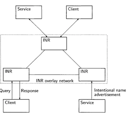
INS uses a decentralized network of intentional name resolvers (INRs) to discover names and route messages (see Figure 2.2). These resolvers self-configure into an application-level overlay network and resources can use any of them to resolve requests and advertise services. When a message arrives at an INR, it is resolved on the basis of the destination name and then forwarded, along with the associated application data, directly to the end-node. In addition, a client can 19
Service Client
NR
INR INR
INR overlay- -network
---Query Response Intentional name advertisement
Client Service
Figure 2.2: Architecture of the Intentional Naming System. A client makes intentional name-based queries on INRs, while services periodically advertise their intentional names to the INR overlay network.
specify metrics (such as "least-loaded" or "shortest queue") which will be incorporated into the message forwarding decision.
INS Naming
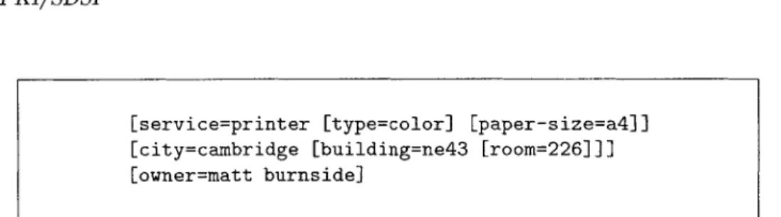
An intentional name is a hierarchy of attributes and value pairs. The hierarchy is arranged such that an attribute-value pair that is dependent on another is a descendent of it. For example, [city=boston] is dependent on [state=massachusetts] so it is denoted [state=massachu-setts [city=boston]]. In addition, when comparing names, INS allows wildcard matching of values using the wildcard token (*). Thus, [state=massachusetts [city=bostonl] and [state=massachusetts [city=*]] are considered a match. See Figure 2.3 for an example of a full INS name.
2.4. SPKI/SDSI
Figure 2.3: An example of a name in the Intentional Naming System. This name describes a specific printer which happens to be a color printer that prints on A4-sized paper. The name also gives the exact location of the printer, as well as its owner. Note that paper-size and type are both dependent on exactly what service is being provided, so they are both descendents of service (paper size has no meaning if the service is, for example, a digital camera).
Name Discovery
Resources periodically broadcast their intentional names to the INS system to describe what services they provide. Each INR listens on a well-known port, which allows it to discover nearby resources. INRs form an overlay network among themselves over which they send soft-state [20] updates of valid names as they are identified.
When a client makes a request for name resolution, INRs use the information obtained using resource advertisements plus the soft-state updates from other INRs for resolution. Using the wildcard matching described previously, a client can lookup particular types of names, or all known names, by specifying the resolution of a broadly matching name. This is useful for clients to bootstrap in a new environment.
Like traditional routers, INRs transfer information between each other using a routing pro-tocol that includes periodic updates as well as triggered updates between neighbors. Periodic updates are used to refresh entries in neighboring INRs and to reliably disseminate names. Trig-gered updates occur when an INR receives an update from one of its neighbors (either an INR or a resource) that contains a new name.
2.4
SPKI/SDSI
Simple Public-Key Infrastructure/Simple Distributed Security Infrastructure (SPKI/SDSI) [8, 9, 10] is a novel public-key infrastructure emphasizing naming, groups, ease-of-use, and flexible authorization. It is these features which made it an ideal security infrastructure on which to
[service=printer [type=colorl [paper-size=a4]] [city=cambridge [building=ne43 [room=2261]] [owner=matt burnside]
base the system described in this document. This section gives an overview of the SPKI/SDSI system, including descriptions of the various certificate formats and an overview of the access control system.
There are two types of certificates in the SPKI/SDSI system: name certificates and autho-rization certificates.
2.4.1
Name Certificates
A SPKI/SDSI name certificate defines a name in the certificate issuer's local namespace. A name certificate has four parts:
issuer The public key that signs the certificate. The issuer is the principal defining the name. identifier An identifier is a single word over some standard alphabet, such as Alice, Bob, or
Friends.
subject A subject is a public key or a single public key followed by one or more identifiers. validity specification The validity specification can take several forms: One possibility is it
can be a range over time (t,
t
2) during which the certificate is valid (i.e., from time t, totime t2, inclusive). The validity specification can also take the form of an online check,
wherein some server address is specified and that server may contain either a whitelist or a blacklist which must be consulted before the certificate is validated.
A name certificate binds local names to public keys and the notation is of the form Ka Bob -+ Kb.
This indicates that the issuer Ka binds the local name Ka Bob to the public key Kb.
Each principal (key pair) can issue name certificates; thus each principal has its own local namespace consisting solely of the names it has defined. This local namespace architecture helps make the infrastructure scalable; a user does not have to ascertain that the names he defines are unique in a global namespace. He can define names which are meaningful to him, which he can easily remember and recognize.
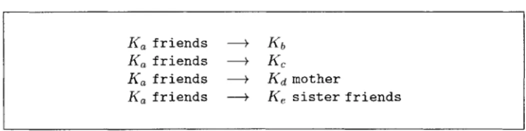
A SPKI/SDSI group is defined by binding a local name to multiple subjects. A group definition explicitly references the members of the group, or it may reference other groups (which could even be defined in another namespace). Figure 2.4 is an example of a SPKI/SDSI group.
2.4. SPKI/SDSI
Ka friends - Kb
Ka friends - K,
Ka friends - K mother
Ka friends -+ K, sister friends
Figure 2.4: An example of a SPKI/SDSI group. Alice (Ka) has defined a group of friends which includes Bob (Kb), Charles (K,), Daniel's mother (Kd mother), and the group consisting of Edward's sister's friends (Ke sister friends). Alice issues these certificates to the respective members of the group. Thus, at a later date, say, Daniel's mother can use the above certificate, Ka friends -+ Kd mother, to prove she is one of Alice's friends.
The ability to define groups is one of the key notions of SPKI/SDSI. This feature facilitates the management of access control lists in the secure resource discovery system, which will be
described in Section 3.6.
2.4.2
Authorization Certificates
An authorization certificate grants a specific authorization to perform a set of operations from the certificate's issuer to the certificate's subject. An authorization certificate has five fields:
issuer The public key that signs the certificate. The issuer is the principal granting the autho-rization.
subject The key or group that is receiving the authorization.
tag A tag represents a set of requests. It specifies the exact operations which the subject is allowed to perform.
delegation bit A bit indicating whether the certificate's subject is allowed to extend the au-thorization defined in this certificate to other principals.
validity specification This is the same as the validity specification described in Section 2.4.1.
An authorization certificate is written Ka -*S El. This means the issuer Ka is granting the authorization in tag T to subject S, with the delegation bit set to true. If the delegation bit is set to false, the certificate is denoted KaE -+S FO.
To keep the SPKI/SDSI infrastructure simple, a single certificate cannot both define a name and grant an authorization. That is, each certificate is either strictly a name certificate or an authorization certificate.
2.4.3
Access Control Lists
An access control list (ACL) protects a resource. It is a list of entries defining who can access the resource and exactly what operations they are allowed to perform. Each entry in a SPKI/SDSI ACL is an authorization certificate where the issuer is, implicitly, the owner of the ACL. That is, each entry has the representation Self M -y+S
l
if the delegation bit is true, or Selfl
-V+Sl
if the delegation bit is false.2.4.4
Certificate Chain Discovery
The certificate chain discovery algorithm [7] constructs chains of certificates leading from an entry on an ACL to a principal's public key. For example, imagine Alice, (Ka), wishes to print to Charles' printer which is protected by an ACL containing the following entry:
Self d Print)Ke friends E (2.1)
This entry says that Self (Charles) allows all members of the group K, friends to print. Alice must prove that she is one of Charles' friends (K, friends) if she is to print. Let's say that Alice is one of Bob's coworkers, and all of Bob's coworkers are Charles' friends:
Kb coworkers -+ Ka (2.2)
K, friends -+ Kb coworkers (2.3)
These two certificates are stored in Alice's certificate cache, along with the many other certifi-cates she has accumulated. It is the function of the certificate chain discovery algorithm to search through the certificates in the cache and identify the specific chain of certificates lead-ing from K, friends to Ka. More specifically, the certificate chain discovery algorithm takes as input the ACL from the resource (Charles' printer), Alice's public key (Ka), Alice's set of
2.4. SPKI/SDSI
certificates, Alice's request (represented as a tag), and a timestamp. If it exists, the algorithm returns a chain of certificates which proves that Alice's public key is authorized to perform the operations specified in the tag, at the time specified by the timestamp. If the algorithm is unable to generate a chain because Alice does not have the necessary certificates, or if her key is directly on the ACL, the algorithm returns an empty certificate chain. In this particular example, the algorithm will return certificates 2.2 and 2.3 which prove that Alice is a member of K, friends.
2.4.5
Certificate Chain Verification
Certificate chain verification is the simple complement of certificate chain discovery. Given a certificate chain, it is the function of the certificate chain verification algorithm to determine whether the chain does, indeed, prove that the client's public key is authorized to perform the operations specified in the tag. That is, it verifies that there is a chain of authorization from an entry on the ACL to the client's key, via the given chain of certificates.
2.4.6
Certificate Revocation
Certificate revocation is a difficult issue in public-key infrastructures. SPKI/SDSI allows several different forms of revocation. Firstly, a principal may publish a list of all his revoked certificates (i.e. a certificate revocation list). This is a commonly used scheme, but does not scale well. Additionally, if the principal does not publish the certificate revocation list frequently, the recipient of a certificate must make decisions about the validity of the certificate based on what may be an out-of-date revocation list.
Revocation in SPKI/SDSI can also take place through use of an online check. Each SPKI-SDSI certificate contains a validity specification (as described in Section 2.4.1) and that may contain the address of a server which stores a whitelist or blacklist (revocation list). With appro-priately distributed robust validity servers, online checks can scale much better than certificate revocation lists.
The final form of revocation, the form encouraged by SPKI/SDSI, is the use of short validity periods. Rather than storing an online check, a validity specification can identify a time period over which the certificate is guaranteed to be valid. When the certificate expires, a new one is issued, again with a short time period. With suitably short time periods, revocation simply 25
Chapter 3
System Design
This chapter discusses the overall design of a secure resource discovery system, based on the idea of supporting all communication with a proxy-based architecture. There are a number of goals which this design attempts to meet:
" Identification and authentication of all resources. It must be possible for any resource to authenticate any other resource with which it communicates.
* Secure communication between resources. This implies a secure mechanism for distributing encryption keys.
" Usage/access permissions for all resources. The administrator for each resource must have fine-grained control over access to all resources he administers.
" Easy ACL maintenance. In traditional public-key infrastructures, maintenance of ACLs is non-trivial.
* Configuration-free startup. The system must bootstrap with a minimum of user or ad-ministrator interaction.
" Support for a heterogeneous networking environment. The system must provide support for a wide variety of hardware and software resources.
The system described in this chapter achieves each of these goals successfully, and with a mini-mum of overhead.
3.1
Proxy-Based Architecture
Each resource in the system has a proxy [2] that runs on a computationally powerful machine
(e.g. a desktop or handheld computer). There is a one-to-one correspondence between resources and proxies; every resource has one proxy, and each proxy represents one and only one resource. This feature allows the division of communication within the system into two sets of protocols. There is one set of protocols for communication between proxies, and one set for communication between a resource and its proxy.
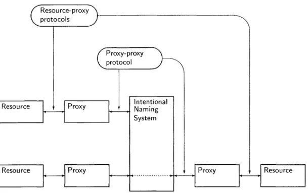
With this in mind, we can fix the proxy-proxy protocol to be a single, well-known protocol. If the proxy-proxy protocol is fixed, the resource-proxy protocols can be varied between resources. In fact, each resource can use a different protocol. This is particularly powerful since the variety of resources is large (ranging from computationally lightweight devices like light bulbs, all the way up to desktop computers). There is not necessarily one single protocol that is suitable for all resources. Figure 3.1 is an overview of the proxy-based architecture.
In addition to providing a "translation service" between the proxy-proxy protocol and the resource-proxy protocol, a proxy also serves as a repository for the security credentials of its resource. It stores the resource's SPKI/SDSI certificates, any ACLs that govern access to the resource, and any symmetric keys necessary for enacting the resource-proxy protocol. It acts as a guardian deciding, based on the stored ACLs, which other resources may make use of its resource. Because the proxy provides these services, it must run on a computer that the resource's administrator trusts, since running it on an untrusted computer implies that its security credentials (e.g., private keys) would be compromised.
The proxy also serves as the focal point for the discovery process. After its creation (the bootstrap process is described in Section 3.4), it provides a client to the Intentional Naming System, representing its particular resource. Thus, all discovery functions can be filtered by the access control lists stored on the proxy.
3.2
Resource-Proxy Protocol
The resource-proxy protocol depends on the type and network location of the resource. That is, a computationally lightweight device must use a lightweight protocol, while a desktop computer
3.2. RESOURCE-PROXY PROTOCOL protocols Proxy-proxy protoc 3e2.1 Se l A n SIntentional ThR ipeshesource Namin System
Resource Proxy Prroxy Resource
Figure 3.1: Architecture of the proxy-based system. Communication between proxies uses one global protocol, while the protocol for communication between a proxy and its resource may take many forms.
can use a sophisticated asymmetric key protocol. Below are examples of a number of different
protocols and situations in which they might be useful.
3.2.1 Shell Account Server
The simplest case for the resource-proxy protocol is one in which the proxy is running on the same physical machine as the resource. This is the case with a shell account server. A user (a user is simply another "resource") logs onto his shell account using the proxy-proxy protocol. The proxy then passes information to the shell server directly by making the appropriate function calls. Since the security credentials are being passed from one program to another directly, through a function call, it is clear there is no need for any further security between the proxy and the resource. Remember, we assume that the proxy is running on a trusted computer. If the computer were not trusted, it would become necessary to place the proxy on another machine.
3.2.2
Remote Shell Account Server
This situation is identical to Section 3.2.1 except that the shell server is running on a remote computer. It is no longer possible for the proxy to make function calls directly on the shell server, so it becomes necessary to secure the protocol between them. However, both the proxy and the shell server are running on desktop computers, so the protocol can be quite sophisticated. In fact, an excellent candidate would be one which duplicates the proxy-proxy protocol because it gives both server and client authentication.
3.2.3
Project Oxygen: K21 Badge
The K21 badge [15] is a lightweight circuit board designed to be worn by an individual as a badge (for more information, see Section 2.2). It communicates with its proxy using a custom radio frequency protocol. Since its sole processor is an Atmel ATMega103L, any encryption performed
on the device must be lightweight. This generally excludes asymmetric encryption (i.e. public-key cryptography). Instead, we use a hashed message authentication code (HMAC) [13] based on MD5 [22] for authentication and use the RC5 [23] cipher for encryption. Both of these algorithms can be implemented in small code space, and neither is computationally intensive.
The K21 badge and its proxy share two 128-bit keys. Every packet passed between the K21 badge and the proxy is signed (authenticated) with one key, using HMAC-MD5, and then encrypted with the other, using RC5. The result is a lightweight protocol capable of being tunneled over the radio frequency communication used by the K21 badge.
3.3
Proxy-Proxy Protocol
The proxy-proxy protocol is based on SPKI/SDSI, a public-key infrastructure. Some details and background on SPKI/SDSI are given in Section 2.4. When one proxy sends a request to another, we say the requesting proxy is the client proxy (referred to as Alice) and the destination proxy is the server proxy (referred to as Bob). Each has a public-private key pair (Da, Ea and
Db, Eb), and Bob possesses an ACL that governs access to his resource. The protocol consists of four steps:
3.3. PROXY-PROXY PROTOCOL
2. Bob checks his ACL for Ea (the public key corresponding to Da). If he finds Ea on the list, he immediately performs the request, and the protocol is complete. If he does not find it, he returns the ACL to Alice.
3. If the protocol did not complete in the previous step, Alice performs certificate-chain discovery (Section 2.4.4) in order to find a chain of certificates between her public key and one of the keys on the ACL. She returns this chain to Bob, along with a copy of her original request,
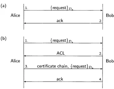
{request}D.-4. Bob verifies the chain by using the certificate-chain verification algorithm (Section 2.{request}D.-4.5). If it is valid, he performs the request and sends an acknowledgment. Otherwise, he refuses. Figure 3.2 is a graphical representation of this protocol. This protocol is similar to the protocol described in [3] for use with HTTP, but it is generalized beyond HTTP; it allows for generic message passing. This protocol, as described, addresses the issue of providing client access control. It does not ensure confidentiality, authenticate servers or provide protection from replay attacks from the network.
The Secure Socket Layer (SSL) protocol is the most widely used security protocol today, and the Transport Layer Security (TLS) protocol is its successor. Principal goals of SSL/TLS [21] include providing confidentiality and data integrity of traffic between the client and server, and providing authentication of the server.1 The SPKI/SDSI proxy-proxy protocol can be layered over a key-exchange protocol like TLS/SSL to provide additional security. TLS/SSL currently uses the X.509 PKI [12] to authenticate servers, but it could just as easily use SPKI/SDSI. In addition to the previously stated features, SSL/TLS also provides protection against replay attacks from the network and protection against man-in-the-middle attacks.
SSL/TLS authenticates the server proxy. However, it does not determine whether the server proxy is authorized to accept the client's request. For example, imagine that the client proxy wants to print a 'top secret' document and only certain printers should be used to print top secret documents. With SSL/TLS and the SPKI/SDSI proxy-proxy protocol described so far, if the client proxy goes to a given printer and attempts to print, it will be able to determine that the public key of the server proxy is bound to a particular network address, and the server
'There is support for client authentication, but it is optional.
(a) 1. {request}D. Alice Bob ack 2. (b) 1. {request}D, ACL 2. Alice Bob
3. certificate chain, {request}D ,
ack 4.
Figure 3.2: Proxy-proxy protocol. In case (a), Alice's key is directly on Bob's ACL, so Bob honors the request immediately and responds with an acknowledgment. In case (b), Alice's key is not directly on Bob's ACL, so he returns his ACL. Alice performs certificate chain discovery in an attempt to find a chain of certificates that proves she is allowed to access the requested resource. When she finds it, she returns the chain, along with a copy of the original request to Bob. Bob verifies the chain and honors the request.
proxy will know that the client proxy is authorized to print to it. However, the client proxy will still not know if the server proxy is actually authorized to print top secret documents. If it sends the top secret document to be printed, the server proxy will accept the document and print it, even though the document should not have been sent to it in the first place.
To resolve this problem, we extend the proxy-proxy protocol so that the client requests authorization from the server and the server proves to the client that it is authorized to handle the client's request (before the client sends the document off to be printed). To extend the protocol, the protocol described in Section 3.3 is run from the client proxy to the server proxy, and then run in the reverse direction, from the server proxy to the client proxy. Thus, the client proxy will present a certificate chain proving that it is authorized to make its request, and the server proxy will present a certificate chain proving that it is authorized to accept and perform the client's request.
3.4. RESOURCE-PROXY BOOTSTRAPPING
3.4
Resource-Proxy Bootstrapping
When a new resource is introduced, it must be possible to create and attach a proxy in a secure fashion. However, a brand new resource has, in general, no security credentials and no knowledge of network topology. To resolve this issue, we assume that all users of this system will wear a K21 badge, and then introduce the idea of a root proxy.
A root proxy is associated specifically with a user; it is the proxy for that user's K21 badge. All resources must be initialized by a specific user (i.e., the administrator for that resource). When the resource turns on for the first time, the administrator places his K21 badge in physical contact with the resource. At this time, a four step protocol takes place:
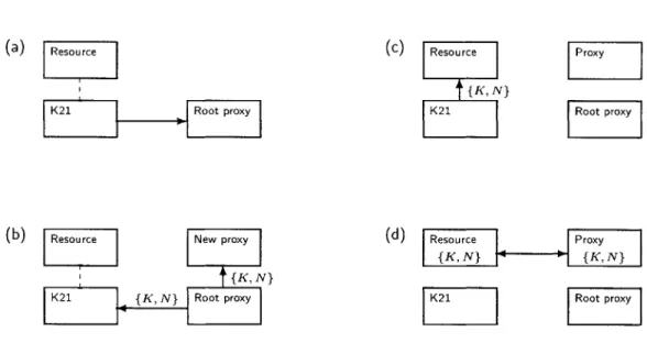
1. The K21 badge sends a message (using the secure resource-proxy protocol) notifying its proxy (the root proxy) that a new resource is being introduced. (Figure 3.3a.)
2. The root proxy creates a fresh set of security credentials and spawns a new proxy, giving it the necessary portions of these new credentials. It then sends the complementary portion of the credentials2 and the network location of the new proxy back to the badge (again, using the secure resource-proxy protocol). (Figure 3.3b.)
3. The badge then uploads, over the physical connection between it and the new resource, the security credentials and the network location of the new proxy. (Figure 3.3c.)
4. The resource uses this information to securely initiate communication with its freshly spawned proxy. It can, at this point, upload information such as its intentional name. (Figure 3.3d.)
At the conclusion of the above protocol, the new device has a proxy with which it shares a set of security credentials, and at no time has any critical information been left in the clear. Also, note that when the new proxy is spawned, the root proxy installs it with some pre-defined default ACL which will remain in place until modified by the administrator.
2
1n the case of symmetric key encryption, the "complimentary" portion of the credentials is simply a copy of the keys. This is not necessarily the case with asymmetric cryptographic protocols.
(a) Resource
K21 Root proxy
(b) Resource New proxy
{K, N} K21 {K, N} Root proxy (c) Resource {K, N} K21 I Proxy Root proxy (d) Resource Proxy { K, N} _J {. fK, N} K21 Root proxy
Figure 3.3: The resource-proxy bootstrapping protocol. Initially, in (a), the K21 is placed in physical contact with the new resource. The K21 notifies its proxy that a new resource is being added. In
(b), the K21's proxy has created a new set of cryptographic keys K and a new network location N, and spawned a new proxy with those keys at that location. It returns this information to the K21. In
(c), the K21 uploads {K, N} to the resource. Finally, in (d), the resource uses K and N to initiate a resource-proxy protocol session with the new proxy.
3.5
Proxy Discovery
Once a resource has been assigned a proxy, the next step is to identify and communicate with other resources (through their respective proxies). This discovery takes place through use of the discovery facilities of the Intentional Naming System, as described in Section 2.3.1.
When a proxy comes online, it begins to periodically advertise its name (i.e. the name of the resource it represents) to the INS system. If a nearby INR hears these periodic announcements, it will recognize the reception of a new name and will add it to its internal database. The name will also be propagated throughout the INS overlay network, so within a short period of time, all INRs will be aware of its presence. At that point, other resources can make queries for this particular resource.
3.6. ACL MAINTENANCE 35
3.6
ACL Maintenance
One of the most useful features of this system is the ease with which it allows ACL maintenance. The power is derived primarily from the underlying use of SPKI/SDSI. In fact, it is often the case that adding a user to an ACL or removing him from it can be done without editing the ACL at all.
Imagine Alice is the administrator for a computer cluster of twenty computers at company XYZ and each computer has the following access control list:
Self
E
Login ' Ka ] (3.1)Self Login K, Ka coworkers
El
(3.2)This ACL says that Alice, Ka, and Alice's coworkers, Ka coworkers, have permission to log in to each computer. Now imagine Bob, Kb, joins company XYZ. In a traditional access control structure, if Alice wished to give Bob access to the computer cluster, she would have to go to each computer individually and add his name to that machine's ACL. With SPKI/SDSI, on the other hand, Alice's job is much easier. She can issue the following name certificate to Bob:
Ka coworkers -+ Kb (3.3)
This certificate proves that Bob is one of Alice's coworkers. When he presents this certificate to any cluster computer, along with a request signed by his key, Kb, the computer will allow him to log on. Revoking access to a resource is just as easy. Rather than having to go to each computer and remove Bob from the ACL, Alice can simply revoke his certificate [3].
3.7
Example Session
Alice has just purchased a brand new printer, and she wishes to install it and print a document. This section will explore the steps that must take place. The initial players in the system are Alice (Ka), her K21 badge, and the K21 proxy with a default ACL: Self
El
,+KaEl
(Where '*' is a wildcard, implying Alice can perform all actions).Alice sets up the new printer and plugs it in. Initially, it has no proxy so there is no way to print to it. Alice initiates the resource-proxy bootstrap protocol by placing her K21 badge in physical contact with the printer and indicating to the badge that she is introducing a new resource. The badge then contacts its proxy with this information. The proxy generates a fresh set of security credentials for the new resource and spawns a new proxy with those credentials and a copy of the default ACL. The proxy returns the security credentials, along with the network location of the new proxy, to the badge. The badge uploads this information to the printer over the physical connection.
The printer now has the means to communicate securely with its new proxy. If Alice wishes to print a document, she instructs her proxy to send a request to the printer's proxy:
{print foo.doc}Ka. The printer's proxy checks its ACL and discovers that indeed Ka is on there,
so it immediately prints foo.doc.
Now Alice wants to allow her friend Bob, Kb, to print to her printer. She adds the following entry to the ACL on the printer: Self
El
Print Kafriends
,
and issues a certificate to Bob indicating that he is, in fact, her friend: Ka friends - Kb.Bob attempts to print a document by sending {print bar.doc}Kb to the printer's proxy. The printer's proxy examines its ACL and sees that Kb is not on it. It rejects the request and sends its ACL to Bob's proxy. Bob's proxy uses the certificate chain discovery algorithm which discovers the certificates that prove Bob is Alice's friend, and that Alice's friends are allowed to print to the printer. Bob's proxy returns this information to the printer's proxy which verifies it and prints the document.
3.8
Design Discussion
This system, as described, features client and server proxy authentication, fine-grained access control, and private communication. It does not, however, defend the Intentional Naming System against attacks from masquerading resources. That is, if a resource makes false claims about its attributes, INS will not recognize this fact. The result is that responses to INS queries may contain invalid resources. This may not strictly be a problem for end-users since any attempt to use these invalid resources will fail during the server authentication stage of the proxy-proxy
3.8. DESIGN DISCUSSION
protocol. It is certainly a potential problem for the Intentional Naming System since it can result in a number of attacks, including denial of service. Resolving this issue is an area of
active research.
There are also a variety of questions surrounding the use of access control within the resource discovery protocol. Imagine Alice makes a query for a list of nearby printers. She receives a response containing a list of ten printers. She attempts to print to the first printer and if that attempt fails, she moves on to the next printer on the list. It is entirely possible that she is not on the ACL for the first nine printers, so her first nine attempts would fail, and she'd finally succeed on the tenth printer. This is clearly inefficient and it would be desirable for the response she receives to only contain the one printer to which she has access. Improving the efficiency of this mechanism is an area of active research. Additionally, there are situations where it might be desirable to introduce a resource into the system but not to allow some users to know of the
existence of that resource. That is, that resource can only be returned in a query to specifically
chosen users. This is also an area of active research.
Chapter 4
Implementation
To test the principles discussed in this document, a simple version of the system was implemented in Java. In order to simplify testing and analysis, a simpler resource discovery system was designed and built, rather than making use of INS. The implementation consists of four primary modules: Event, Resource, Proxy, and NameResolver.
4.1
Event Hierarchy
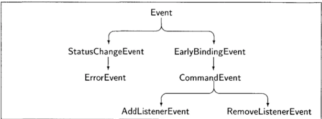
Inter-proxy and proxy-name resolver communication is performed using packets that are part of the Event hierarchy. An Event is simply a message with an origin. An EarlyBindingEvent inherits origin from Event and adds a destination. From these descend a variety of events, including a CommandEvent and a StatusChangeEvent. Figure 4.1 details the event hierarchy.
An event-based communications mechanism is useful because it makes a number of compu-tations more efficient. In particular, it is often desirable to know when a particular resource has changed state (a lightbulb has turned on, a computation has finished, etc.). The naive solution is to repeatedly poll the resource; from a networking standpoint it is much more efficient for the resource to generate an event and notify all listeners when its state has changed.
Event
StatusChangeEvent EarlyBindingEvent ErrorEvent CommandEvent
AddListenerEvent RemoveListenerEvent
Figure 4.1: Part of the event hierarchy. At the root of the tree is an Event class from which descends a variety of other events. Note that early-binding events such as CommandEvent must have an origin and a destination, while late-binding events, such as StatusChangeEvent do not.
4.2
Resource Module
Each instance of the Resource module is custom software written for the specific device. The front end of the module implements the resource-proxy protocol, and the back end implements other device-specific functions. For instance, a Resource module for a speaker implements the resource-proxy protocol, and uses the
j
avax. sound. * package for speaker output. The Resource module may also provide support for updating its proxy with Cricket location information, if the resource is so equipped.4.3
Proxy Module
The Proxy module has a very simple interface: it only presents four primary functions.
Proxy. send(Event event) Sends event to the nearest NameResolver to be routed to its des-tination (i.e., event. getDest inat ion) ).
Proxy. event0ccurred(Event event) This is a call-back method which is called whenever a message (an event) arrives at the proxy.
Proxy. start 0 This function brings the proxy online and begins the resource discovery process. The proxy begins advertising for a NameResolver.
4.4. NAMERESOLVER MODULE
Proxy. stop() This function brings the proxy offline and ends the resource discovery process. It stops advertising its resource.
The Proxy module also stores all security credentials for the Resource and has a corresponding set of functions with which to operate on those credentials. It implements the proxy-proxy protocol described in Section 3.3. The Proxy module also accepts plugins for application-specific behavior. It features a simple API for installing plugins, which allows the user to customize the proxy's behavior in response to each type of message it receives.
4.4
NameResolver Module
NameResolvers give a subset of the functionality provided by INS. Their presence is simply for ease of testing, analysis and debugging. A NameResolver multicasts periodic advertisements on a well-known UDP/IP multicast channel. Any proxies which receive this advertisement respond with a resource description (i.e., their intentional name). This information is treated as soft state [20] and used to update the rest of the NameResolvers.
NameResolvers themselves participate in the discovery system. Thus, each NameResolver is aware of the presence of all other NameResolvers. A special set of ServerUpdate events is used for naming updates between resolvers. Each NameResolver is kept updated with the names of
all resources in the system.
4.5
Analysis
The discovery process used by this implementation is efficient. It uses little bandwidth and state inconsistencies are kept to a minimum. A NameResolver broadcasts an advertisement periodically, every u time units, at times Po...., and it takes some delay d for it to receive a resource description back from a proxy:
d = rto + c + rti (4.1)
Where rto is the advertisement's one-way travel time from the name resolver to the proxy, c is processing delay on the proxy and rti is the resource description's one-way travel time back to
the name resolver.
Imagine a proxy comes online at time to and goes offline at time ti. In the worst case:
to = Po+rto+e (4.2)
t = P+rtic+cE (4.3)
assuming rto rti < u. That is, the proxy comes online some infinitesimal time
E after
the most recent advertisement has gone past, and goes offlineE time units after sending a
resource description. The name resolver spends to - Poa
rto time units with the mistakenunderstanding that the proxy is offline, when in fact it is online, and t, - P., rti + c time
units with the understanding that the proxy is online when, in fact it is offline. The total error time is rto + rti + c = d. Thus, the name resolver is mistaken for, at most, d time units.
The result is that in some rare cases, invalid state can be returned in response to a query. In one case, a client makes a query for a resource that is online but has not yet completed the discovery process. The client will receive a response packet containing the next-best match and will simply use that resource instead. In the other case, the client makes a query for a resource that has gone offline, but the NameResolvers have not recognized this fact. In this case, the client will receive that non-existent resource in the response packet. When the client attempts to connect to the resource and fails, it can simply repeat its query, or perform a query for the next-best resource.
The implementation does not necessarily use network bandwidth in the most efficient manner. With n proxies on a given UDP/IP multicast channel, each NameResolver advertisement results in n resource descriptions. On average, a NameResolver will receive ! resource descriptions perU
second. Thus, for large
n
or small u, the NameResolver network stack may overflow. One solution is to dynamically adjust u as n varies; varying u as n changes can maintain a constant frequency of incoming resource description.4.6
Sample Applications
To test this implementation, we built several sample applications. This section discusses two of them.