Publisher’s version / Version de l'éditeur:
Optical Interference Coatings, OSA Technical Digest, 2010, TuB, p. TuB2,
2010-06-10
READ THESE TERMS AND CONDITIONS CAREFULLY BEFORE USING THIS WEBSITE. https://nrc-publications.canada.ca/eng/copyright
Vous avez des questions? Nous pouvons vous aider. Pour communiquer directement avec un auteur, consultez la première page de la revue dans laquelle son article a été publié afin de trouver ses coordonnées. Si vous n’arrivez pas à les repérer, communiquez avec nous à PublicationsArchive-ArchivesPublications@nrc-cnrc.gc.ca.
Questions? Contact the NRC Publications Archive team at
PublicationsArchive-ArchivesPublications@nrc-cnrc.gc.ca. If you wish to email the authors directly, please see the first page of the publication for their contact information.
NRC Publications Archive
Archives des publications du CNRC
This publication could be one of several versions: author’s original, accepted manuscript or the publisher’s version. / La version de cette publication peut être l’une des suivantes : la version prépublication de l’auteur, la version acceptée du manuscrit ou la version de l’éditeur.
Access and use of this website and the material on it are subject to the Terms and Conditions set forth at
Optimum Phase for Thin Film Synthesis by Fourier Transforms
Verly, Pierre G.
https://publications-cnrc.canada.ca/fra/droits
L’accès à ce site Web et l’utilisation de son contenu sont assujettis aux conditions présentées dans le site LISEZ CES CONDITIONS ATTENTIVEMENT AVANT D’UTILISER CE SITE WEB.
NRC Publications Record / Notice d'Archives des publications de CNRC:
https://nrc-publications.canada.ca/eng/view/object/?id=8abfd276-a3c0-4055-831a-94d2c6bace03 https://publications-cnrc.canada.ca/fra/voir/objet/?id=8abfd276-a3c0-4055-831a-94d2c6bace03Optimum Phase for Thin Film Synthesis by Fourier
Transforms
Pierre G. Verly
National Research Council of Canada, Institute for Microstructural Sciences, 1200 Montreal Road, Ottawa, Canada ON, K1A 0R6 Pierre.Verly@nrc.ca
Abstract: An optimum phase is developed for rugate reflector design by a simple Fourier
Transformation. Surprisingly good solutions are obtained for arbitrary spectral curves by phase shaping alone.
© 2010 Optical Society of America
OCIS codes: (310.0310) Thin films; (310.1620) Interference coatings; (310.6805) Theory and design; (310.5696)
Refinement and synthesis methods
Thin film synthesis techniques can generate solutions from much more elementary starting designs than conventional refinement. This is an appreciable advantage because the demands on filter performance increase continuously. One of the first practical synthesis approaches, proposed several decades ago but still of interest in particular for rugate filters, establishes an analytical relationship between a refractive index profile n(x) and its transmittance T(σ) through a Fourier transform [1,2]:
σ σ φ π σ σ π )] ( exp[ ) ( ) , ( ~ ) ( ln 0 i T Q i T Q i FT n x n = ⎯ ⎯ → ← ⎟⎟ ⎠ ⎞ ⎜⎜ ⎝ ⎛ (1)
In this equation x is twice the centered optical thickness (see the figures), n0 is a constant, T the transmittance and
σ=1/λ the wavenumber or inverse wavelength. Losses and dispersion are ignored in the original theory but there are indirect ways of introducing them in the calculations.
The complex function in Eq.(1) is known as the Q-function. Unfortunately the analytical forms of the Q-magnitude Q(T) proposed in the literature lose their accuracy as the reflectance R=1-T increases. Q is approximately equal to R1/2 when R is small. The Q-phase φ(σ) is usually unknown and has to be generated in the synthesis process. Additional errors are often introduced, for example when n(x) is forced to fit within prescribed thickness and refractive index limits.
) , ( ~T σ
Q
Many efforts have been made to improve the Q-function, either by numerical iterations or analytically [3-7]. Most of the efforts concentrated on the magnitude Q(T). Much less has been said on the phase except in rare situations where it is specified, or to recognize that it has a profound effect on the shape of the refractive index profile [8, 9]. Multiple filter solutions of essentially the same reflectance in the region of interest but different phases are frequently possible, from which the most suitable for fabrication can be selected.
This work concentrates on the phase φ(σ). An interesting phase first applied to thin films by Druessel and recently implemented by Cheng for the design and fabrication of complex rugate filters is known as the SWIFT phase [7,10]: σ η ν ν ν ν ν ν π σ φ σ η 0 0 0 2 0 2 0 1 ( ) ) ( 2 ) ( x d d Q d Q x x + − =
∫∫
∫
∞ (2)In this equation, x0 and x1 are thickness limits defining a region where the refractive index modulation is uniformly
distributed. The slope dφ/dσ is gradually adjusted so that different spectral regions are mapped to non-overlapping regions of the system in order to avoid the build up of excessive refractive index amplitude [tilting the phase shifts
n(x) along the x axis]. This approach is excellent for chirped wide-band reflectors. It does not work as well for
narrow bands because it is more difficult to avoid the overlap of refractive index contributions arising from different spectral regions.
Arbitrary reflectance bands are easily handled when the SWIFT phase (or any other phase) is optimized. This is an interesting exercise. In this work the optimization is performed with an upgraded version of the approach described in Ref.[6]. The new version has analytical gradients of the type:
a147_1.pdf
OSA / OIC 2010
TuB2.pdf
... , 2 , 1 , = ∂ ∂ ∂ ∂ = ∂ ∂
∑
n i k n M M i k i i k φ φ (3)where M is a standard merit function characterizing the reflectance error (desired – calculated). ni= n(xi) and
φk=φ(σk) are points on the x and σ grids used in the calculations. The derivative ∂n/∂φ is obtained from Eq.(1) and
∂M/∂n is the same as in Ref.[11]. A Quasi-Newton algorithm minimizes the merit value by varying the phase. The magnitude of the Q-function can be adjusted in a similar way. Analytical gradients and the way they are calculated make a significant difference in terms of accuracy and computation speed. The results of the phase optimization are surprisingly good and shed new light on the Fourier Transform Method in thin films.
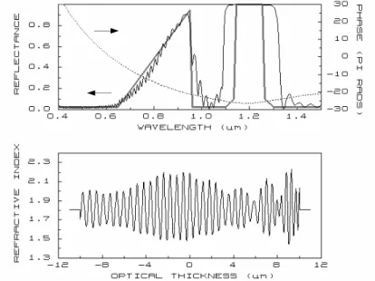
Figure 1: Fourier Transform design generated by the plotted SWIFT phase. Thick grey line: reflectance target. Solid black lines: refractive index profile and its reflectance.
Figure 1 illustrates the design obtained when Q-function [3,4]
⎟ ⎟ ⎠ ⎞ ⎜ ⎜ ⎝ ⎛ − − =ln 1 1 1 8 T T Q (4)
and the SWIFT phase represented by a dotted black line are substituted in Eq.(1). The spectral target represented by a thick grey line consists of a linear ramp from 2% to 95% reflectance and a narrow band of 99.9% reflectance. Elsewhere the reflectance should be < 2%. Light is at normal incidence. The refractive index profile represented in the lower part of the figure has an optical thickness of 20μm, essentially what is needed for the narrow reflectance band alone. For simplicity the system is immersed in a medium of average index (1.8). The specified index limits are 1.45 and 2.25.
The calculated refractive index modulation is chirped and relatively well distributed in the prescribed thickness and refractive index spaces. The index spread along the thickness axis (and the related SWIFT phase curvature) is adjusted by means of the x1-x0 term in Eq.(2). The calculated reflectance is reasonable, especially for wavelengths
below 0.95μm, considering the high-reflectance limitations of the Fourier Transform theory and the limitations of the SWIFT phase for narrow reflectance bands. The beats in the index modulation reveal that the contributions from the two reflectance bands overlap, violating the SWIFT phase conditions. Nevertheless this result constitutes a good start for phase refinement.
Figure 2 shows the optimized solution. The reflectance plotted on two different scales is considerably improved. There is also a large change in the Q-phase and the refractive index profile. A Fourier analysis reveals that the index modulation responsible for 2nd reflectance band is essentially a wavelet (apodized sinusoid [12]) spread over the whole available thickness. The index contribution from the triangular band is mostly concentrated on the right hand side of the system in the region of the largest index beats.
The increased Q-phase curvature across the 2nd reflectance band stretches the index profile further by comparison to Fig.(1). It is easily verified that the excess index modulation generated by Q(T) still exists but it is shifted out of the allowed thickness range and is thus not included in the design. Interestingly, the results are quite
a147_1.pdf
OSA / OIC 2010
TuB2.pdf
insensitive to the accuracy of Q(T) as long as this function is able to generate enough reflectance. Several other published forms of Q(T) also worked. This phase shaping procedure is remarkably efficient. Introducing Q(T) in the optimization does not improve the solution much. Clearly the optimized Q-phase is not unique and multiple solutions of nearly the same reflectance are possible.
Figure 2: Modified design after Q-phase refinement. The initial and final Q-phases are shown.
It is interesting to note that related work exists in laser pulse technology [13]. However the height of the pulses does not have to be fitted accurately and the implementation is totally different. To my knowledge the application of this phase-only design approach to thin films is new. This work further stresses the importance of the phase in thin film synthesis by Fourier transforms.
References
1 L. Sossi, "A Method for the Synthesis of Multilayer Dielectric Interference Coatings", Eesti NSV Tead. Akad. Toim. Fuus. Mat. 23, 229-237
(1974). An English translation is available from the Translation Services of the Canada Institute for Scientific and Technical Information, National Research Council of Canada, Ottawa, Ontario, Canada KlA 0R6.
2 J.A. Dobrowolski and D. Lowe, "Optical thin film synthesis program based on the use of Fourier transforms", Appl. Opt. 17, 3039-3050
(1978).
3 B. G. Bovard, "Fourier transform technique applied to quarterwave optical coatings", Appl. Opt. 27, 3062-3 (1988). 4 Walter J. Wild, "Analytic improvement of Sossi's Q function", Appl. Opt. 28, 3272-3 (1989).
5 P. G. Verly and J. A. Dobrowolski, "Iterative correction process for optical thin film synthesis with the Fourier transform method", Appl. Opt.
29, 3672-84 (1990).
6 P. G. Verly, "Fourier transform technique with refinement in the frequency domain for the synthesis of optical thin films", Appl. Opt. 35,
5148-54 (1996).
7 Xinbin Cheng, Bin Fan, J. A. Dobrowolski et al., "Gradient-index optical filter synthesis with controllable and predictable refractive index
profiles", Opt. Express 16, 2315-2321 (2008).
8 R. Szipocs and A. Kohazi-Kis, "Theory and design of chirped dielectric laser mirrors", Applied Physics B: Lasers and Optics 65, 115-135
(1997).
9 Pierre G. Verly, A. V. Tikhonravov, and A. D. Poezd "Multiple solutions to the synthesis of graded index optical coatings", in Inhomogeneous
and Quasi-Inhomogeneous Coatings, (SPIE -The International Society for Optical Engineering, 1993), Vol. 2046, pp. 9-16.
10 Jeff Druessel, Jeff Grantham, and Peter Haaland, "Optimal phase modulation for gradient-index optical filters", Opt. Lett. 18, 1583 (1993). 11 P. G. Verly, A. V. Tikhonravov, and M. K. Trubetskov, "Efficient refinement algorithm for the synthesis of inhomogeneous optical coatings",
Appl. Opt. 36, 1487-95 (1997).
12 W. H. Southwell, "Using wavelets to design gradient-index interference coatings", in Inhomogeneous and quasi-inhomogenous optical
coatings, (SPIE -The International Society for Optical Engineering, 1993), Vol. 2046, pp. 46-59.
13 Martin Hacker, G. Stobrawa, and Thomas Feurer, "Iterative Fourier transform algorithm for phase-only pulse shaping", Opt. Express 9,
191-199 (2001).
a147_1.pdf
OSA / OIC 2010