Publisher’s version / Version de l'éditeur:
Journal of Power Sources, 196, 22, pp. 9097-9106, 2011-07-26
READ THESE TERMS AND CONDITIONS CAREFULLY BEFORE USING THIS WEBSITE. https://nrc-publications.canada.ca/eng/copyright
Vous avez des questions? Nous pouvons vous aider. Pour communiquer directement avec un auteur, consultez la
première page de la revue dans laquelle son article a été publié afin de trouver ses coordonnées. Si vous n’arrivez pas à les repérer, communiquez avec nous à PublicationsArchive-ArchivesPublications@nrc-cnrc.gc.ca.
Questions? Contact the NRC Publications Archive team at
PublicationsArchive-ArchivesPublications@nrc-cnrc.gc.ca. If you wish to email the authors directly, please see the first page of the publication for their contact information.
NRC Publications Archive
Archives des publications du CNRC
This publication could be one of several versions: author’s original, accepted manuscript or the publisher’s version. / La version de cette publication peut être l’une des suivantes : la version prépublication de l’auteur, la version acceptée du manuscrit ou la version de l’éditeur.
For the publisher’s version, please access the DOI link below./ Pour consulter la version de l’éditeur, utilisez le lien DOI ci-dessous.
https://doi.org/10.1016/j.jpowsour.2011.06.098
Access and use of this website and the material on it are subject to the Terms and Conditions set forth at
A review of accelerated conditioning for a polymer electrolyte
membrane fuel cell
Yuan, Xiao-Zi; Zhang, Shengsheng; Sun, Jian Colin; Wang, Haijiang
https://publications-cnrc.canada.ca/fra/droits
L’accès à ce site Web et l’utilisation de son contenu sont assujettis aux conditions présentées dans le site LISEZ CES CONDITIONS ATTENTIVEMENT AVANT D’UTILISER CE SITE WEB.
NRC Publications Record / Notice d'Archives des publications de CNRC:
https://nrc-publications.canada.ca/eng/view/object/?id=4d19bec5-723e-4ecc-aecf-1337abbc6a37
https://publications-cnrc.canada.ca/fra/voir/objet/?id=4d19bec5-723e-4ecc-aecf-1337abbc6a37
JournalofPowerSources196 (2011) 9097–9106
ContentslistsavailableatScienceDirect
Journal
of
Power
Sources
j ou rn a l h o m e pa g e :w w w . e l s e v i e r . c o m / l o c a t e / j p o w s o u r
Review
A
review
of
accelerated
conditioning
for
a
polymer
electrolyte
membrane
fuel
cell
Xiao-Zi
Yuan,
Shengsheng
Zhang,
Jian
Colin
Sun,
Haijiang
Wang
∗InstituteforFuelCellInnovation,NationalResearchCouncilCanada,4250WesbrookMall,Vancouver,BC,CanadaV6T1W5
a
r
t
i
c
l
e
i
n
f
o
Articlehistory:
Received27May2011
Receivedinrevisedform28June2011 Accepted29June2011
Available online 26 July 2011
Keywords: Conditioning Pre-conditioning Activating Commissioning Break-in Incubation
a
b
s
t
r
a
c
t
Anewlyfabricatedpolymerelectrolytemembrane(PEM)fuelcellusuallyneedsaso-called break-in/conditioning/incubationperiodtoactivateitandreachitsbestperformance.Typically,duringthis activationperiodthecellperformanceincreasesgradually,andthenreachesaplateauwithoutfurther increase.Dependingonthemembraneelectrodeassemblies,thisprocesscantakehoursandevendays tocomplete,whichconsumesaconsiderableamountofhydrogenfuel,leadingtoahigheroperatingcost. Toprovideforacceleratedconditioningtechniquesthatcancompletetheprocessinashorttimeperiod, thispaperreviewsestablishedconditioningprotocolsandreportedmethodstoconditionPEMsingle cellsandstacks,inanattempttosummarizeavailableinformationonPEMfuelcellconditioningandthe underlyingmechanisms.Varioustechniquesarearrangedintotwocategories:on-lineconditioningand off-lineconditioning.Foreachtechnique,theexperimentalprocedureandoutcomesareoutlined.Finally, weaknessesofthecurrentlyusedconditioningtechniquesareindicatedandfurtherresearcheffortsare proposed.
Crown Copyright © 2011 Published by Elsevier B.V. All rights reserved.
Contents 1. Introduction... 9097 2. On-lineconditioning... 9098 2.1. Traditionalbreak-in... 9098 2.1.1. Currentcontrol... 9098 2.1.2. Potentialcontrol... 9099 2.1.3. Temperaturecontrol ... 9100 2.2. Hydrogenevolution/pumping ... 9101 2.3. COoxidativestripping... 9102 2.4. Airbraking... 9102
2.5. Otheron-lineconditioningmethods... 9102
2.6. Combinationofstressors... 9103
3. Off-lineconditioning... 9103
3.1. ElectrochemicalconditioningoftheMEA ... 9103
3.2. Steamingorboilingtheelectrode... 9103
3.3. Componentconditioning... 9104
3.3.1. Membrane... 9104
3.3.2. GDL ... 9104
4. Arapidbreak-inforPBIfuelcells... 9104
5. Reconditioning/cellmaintenance... 9104
6. Concludingremarks... 9105
References... 9105 1. Introduction
Anewlyfabricatedpolymerelectrolytemembrane(PEM)fuel cell usually needs a so-called break-in/conditioning/incubation
∗ Correspondingauthor.Tel.:+16042213038;fax:+16042213001.
E-mailaddress:haijiang.wang@nrc.gc.ca(H.Wang).
period tobeactivatedand reachits bestperformance [1]. This break-inperiodisnecessarytotestandconditionthemembrane electrodeassemblies(MEAs)andotherassembledcomponentsfor operationandtoensurethestackisperformingaccordingto spec-ificationsbeforeassemblingtheentirefuelcellsystem.Typically, duringthisbreak-inperiodthecellperformanceincreases gradu-ally,andthenreachesaplateauwithoutfurtherincrease,e.g.,the powerdensityismonitoreduntilthecurrent densityatagiven
0378-7753/$–seefrontmatter.Crown Copyright © 2011 Published by Elsevier B.V. All rights reserved. doi:10.1016/j.jpowsour.2011.06.098
voltagestopsincreasing.Atthispoint,thebreak-inprocedureis thoughttobecompleteandthecellisbrokeninandreadyto oper-ateundernormal useconditions. Depending ontheMEAs, this processcantakehoursandevendaystocomplete,ifnospecial measuresaretaken.Withtoday’scell/stacktechnology,abreak-in periodof24hisnotuncommon.Thisnotonlyconsumesa con-siderableamountofhydrogenfuel,butalsotakesupsignificant time,resultinginahighcostforoperatingthefuelcell.Thus,MEA conditioningandtestingtechniquesarerequiredtosignificantly reducethebreak-inperiod[2].Ideally,notonlywouldoneliketo havethehighest possiblepowerdensityafterthebreak-in pro-cedure,but onewould also liketominimizethetime toreach thispoint[3].TheUSDepartmentofEnergy(DOE)hasproposed researchprojectsinanattempttoeitherconditiontheMEAbefore stackassemblyandtherebysignificantlyreducetheprocess dura-tion,ordevelopnoveldesignconceptsthateliminatetheneedfor conditioningsteps[4].
Toourknowledge,noin-depthinvestigationshavebeenmade intothecausesforthisconditioningprocess.Thiscanbeattributed toboththelackofdiagnostictoolsavailabletoanalyzetheresults andthelackof experimentaldesignstoexploretheunderlying mechanisms.Toshortenthetimeforelectrodeactivationand max-imizefuelcellperformance,severalmethodshavebeenexamined
[5].Thespecificconditioningorbreak-inprocedureusedamong practitionersvaries,rangingfromperforminganumberof polar-izationcurvesonthenewlyassembledcell/stack,orapplyingan externalloadtothecellandholdingthevoltageorcurrent con-stantforafixedtimeperiod,tosteamingorboilingtheelectrode forashorttime.TheUSFuelCellCouncil(USFCC)hasestablished cellbreak-inprotocolstostandardizetheprocess[6].However, nostandardmeasurementhasbeenestablishedtodeterminethe effectivenessofabreak-inorconditioningprocedure.The follow-ingmethodswererecommendedbyMurthyetal.[3]bymonitoring afuelcell’soutputcurrentdensityat0.6Vandrecordingitasa functionoftimeduringtheapplicationofagivenbreak-in proce-dure.Afterbreak-incompletion(18h),thepowerdensityat0.6Vis extractedfromthepolarizationcurve.Thispowerdensitycanthen beusedasameansofcomparisonbetweencellsthathavebeen conditionedwithvariousprocedures.Additionally,tomeasurethe break-intime,twovaluesarecalculatedfromtherecorded cur-rentdensityat0.6Vversustime.Thefirstisthetimerequiredto reach75%ofthecurrentdensityachievedat18h.Thesecondis thetimerequiredtoreach90%ofthecurrentdensityachievedat 18h.Apparently,betterbreak-inorconditioningprocedureswill giveshortertimes.
Understandingthefundamentalsoftheconditioningprocess helpstoestablishmanufacturingproceduresthatpermit
acceler-atedbreak-inofthecellstack[7].Possibletheorieshavebeenput forwardtoexplainconditioningphenomena:
(i) The activation of thefuel cellhas advantageouseffects on thecatalyst,e.g.,removalofimpuritiesintroducedduringthe processofmanufacturingtheMEAandthefuelcellstack, acti-vationofacatalystthatdoesnotparticipateinthereaction, andcreationofatransferpassageforreactantstothecatalyst
[8].
(ii) Themembranesof a newly assembled fuel cellstack typi-callyneedanincubationphase,aperiodofstackoperationto “break-in”themembranes.Onetheoryisthatthemembranes mayincludecatalystresiduethathinderstheirperformance. Anothertheoryisthatthemembranesareinitiallydry, hinder-ingthestackperformanceuntilthemembraneshydrateduring theincubationperiod[9].
(iii) ToimprovePEMfuelcellperformance,electrodestructures have evolved from polytetrafluoroethylene (PTFE)-bonded electrodes [10] to Nafion-impregnated PTFE-bonded elec-trodes[11]andNafion-bondedelectrodes[12].The introduc-tionofNafionelectrolyteintothecatalystlayers(CLs)extends theelectrodereactionzone,improvescatalystlayerionic con-ductivity,andthusincreasescatalystutilization.However,the initialperformanceofanewMEAwithNafion-bonded elec-trodesusuallyimproveswithtime,astheelectrolytecontained in theelectrodesneedshydration toensurethepassageof hydrogenions.
Fromthesetheories,itisclearthatoneofthemostimportant requirementsforsuccessfulactivationofthefuelcellstack isto controlthewatercontentatacertainlevel.
To provide for accelerated conditioningtechniques that can completetheprocessin ashorttime period,aswellaspresent anunderstandingofthemechanismsbehindthebreak-in meth-ods,this paper reviewsvariousmethods toconditionPEMfuel cells/stacks,includingon-lineandoff-lineconditioningtechniques. 2. On-lineconditioning
2.1. Traditionalbreak-in 2.1.1. Currentcontrol
Investigationshaveindicated thatforcedactivationatvaried currentscanactivatetheMEA[13].Someexamplesthatapply cur-rentcontroltoconditionthecellarelistedinTable1.
Aconstantcurrentdensityof1Acm−2hasbeenappliedbyXie
etal.[14] toactivateacell,usingthefollowingprocedures.The
Table1
Comparisonofconditioningprotocolsundercurrentcontrol.
Testcellconditions Additionalapproach Availableprotocols Authors Reference 25cm2cell,80◦C,NafionNRE-211membrane,
0.40mgPtcm−2forbothelectrodes
Shortcircuitforafewminutes 1Acm−2drawnfromthecellfor6h Xieetal. [14]
65◦
C,Nafion111membraneandPt/C electrodeswithPtloadingsof0.3and 0.5mgPtcm−2ontheanodeandcathode
Open-circuitoperationfor2h A25hMEAconditioningprocedureby controllingthecurrentdensityandholdingfor 5hat50,200,500,800,and1000mAcm−2,
respectively
Bi [15]
50◦C – Firststep:100,200,300,and400mAcm−2for
10min,respectively,followedby500mAcm−2
for30minandarestperiodfor15–20min. Secondstep:holdingthecurrentat 500mAcm−2for10min,thenat800mAcm−2
for40min,followedbyarestperiodfor 15–20min.
Thirdstep:repeatthesecondstep4–6times
Shanetal. [16]
DMFC,25◦C,Nafion®117,Pt/Cforthecathode
andPtRu/Cfortheanode
X.-Z.Yuanetal./JournalofPowerSources196 (2011) 9097–9106 9099
singlecellwasconnectedtotheteststationandheatedto80◦C
withoutgasbeingsuppliedtothecell.Aftertheanodeandcathode humidifierswereheatedto80◦Candthegassupplyinletlineswere
heatedto83◦C,theanodewaselectricallyshortedtothecathode
forafewminutes,andhydrogengaswasthensuppliedtotheanode. Afterremovaloftheshortingleads,humidifiedO2wasintroduced
tothecathode.Whenanopencircuitvoltage(OCV)of∼1.0Vwas reached,aDCloadwasappliedtothecelland1Acm−2wasdrawn
fromthecellfor6h.Thepotentialstabilizedafter∼3h.Attheendof theconditioningperiod,thevariationinthesteadystatepotential was<+1mV.
Followingopen-circuitoperationfor2hforcellwet-up,a 25-hMEAconditioningprocedurebycontrollingthecurrentdensity andholdingitfor5hat50,200,500,800,and1000mAcm−2was
accomplishedbyBi[15]intheprocessofstudyingPt/Cdissolution and depositionin Nafionelectrolyte. The catalyst-coated mem-brane(CCM)wasNafion111membraneandPt/CelectrodeswithPt loadingsof0.3and0.5mgcm−2ontheanodeandcathode,
respec-tively.Celloperatingconditionswere65◦Cwithfullyhumidified
anodeandcathodegasesatatmosphericpressure.
Asimilar procedureofcontrolling currentssequentiallywas patentedbyShanetal.[16].Theentireconditioningprocess con-sists of three steps. The first step includes 100, 200, 300, and 400mAcm−2for10mineach,followedby500mAcm−2for30min
andarestperiodof15–20min.Thesecondstepincludesholding thecurrentat500mAcm−2for10min,thenat800mAcm−2 for
40min,followedbyarestperiodof15–20min.Thenthesecond stepisrepeated4–6times.
Applyinga constantcurrenttoconditionafuelcellwasalso studiedwithdirectmethanolfuelcells(DMFCs).Kim etal.[17]
investigated the effect of an MEA conditioningmethod onthe performanceofaDMFC(Pt/CforthecathodeandPtRu/Cforthe anode)usinganimpedancetechnique.Thefuelcellwasfedwith amethanolsolution(2M,5mLmin−1)andoxygen(250sccm)at
90◦Cand1atm.Temperature(25or90◦C)andaconstantcurrent
of100mAcm−2(appliedornot)wereselectedasvariablesduring
theconditioningperiodtostudytheireffectsontheDMFC’s perfor-mance.Cellperformancewasmeasuredevery6or12hduringMEA conditioning.Immediatelyaftercellperformance measurement, animpedancemeasurementwastaken.Theresultsshowedthat theMEAat25◦Cwithconstantcurrent(100mAcm−2)appliedhad
thebestperformance,andtheresistancedecreasedgraduallydue tohydrationoftheproton-conductingmaterialduringtheentire conditioningperiod.
Otherconditioningprocessesundercurrentcontrolaremoreor lesssimilartotheaboveprocedures.Techniquesrelatedtocurrent controlthatareusedforotherpurposesmightalsobeintroduced totheconditioningprocess.Ahigh-frequencyripplecurrenthas reportedlybeenusedforanagingtest[18].Thecurrentrippleis pro-ducedbysubmittingtheoutputfuelcellcurrenttoahigh-frequency switch.Theripplecurrenteffectsonthefuelcellarethenstudied usinganexperimentalripplecurrentagingtestona220cm25-cell
stackandcomparedwithareferenceagingtest.Thestackisrunin nominalconditionsbutanaccomponentisaddedtothedcload. Theaccomponentisa5kHztrianglewithanamplitudeof∼20%of thedccomponent,tosimulateaboostwaveform.Theresultsshow thatthedegradationslopesofthehigh-frequencyripplecurrent testaremuchhigherthanthoseofthereferencetest.Althoughthis methodisintendedforadegradationtest,itmaywellbeconsidered asaconditioningapproach.
2.1.2. Potentialcontrol
Inadditiontocurrentcontrol,manydifferentbreak-in proto-colsfornewmaterialswithinthefuelcellindustryarerelatedto potentialcontrol,withvariationsinduration,loadcycle,andcell conditions.
Fig.1. Asequentialvoltageprofileforcellconditioningunderpotentialcontrol[8].
2.1.2.1. Potentialcycling. Potentialcyclingisoneofthemost com-monlyusedmethodstoconditionaPEMfuelcell.Atypicalinitial celloperatingconditionatGoreforGoreCCMsisasfollows.Thecell iscycledbetween0.6V,0.3V,andOCV,witheachsetpointheldfor 30–90s,andthecycleisrepeateduntilnofurtherincreaseincell performanceisobserved.Generally,6–8hofbreak-inarerequired. Theoperatingconditionsorinitialsetpointare:Tcell=70◦C,with
100%RHhydrogenat1.2× stoichiometricflowatambientpressure, and 100% RH air at 2.5× stoichiometric flow at ambient pres-sure.UsingGore/PRIMEA®Series5510MEAswithanactivearea
of100cm2andacatalystloadingof0.8mgcm−2,Wengetal.[19]
performedcellconditioningbasedontheGoreprotocol.TheMEA conditioningwasrepeated5–6timesormoreuntiltheperformance reachedarelativelysteadystatebyholdingaconstantvoltageof 0.6Vfor30min,0.4Vfor30min,andthenOCVfor1min.Asimilar cyclingmethodwasalsopatentedbyLee[20]:holdingatOCVfor 2min,0.6Vfor30min,andthen0.4Vforanother30min,at55◦C.
Limetal.[8]patentedamethodofapplyingsequential volt-agestoactivateafuelcell.ThevoltageprofileisshowninFig.1. Aftersupplyinghydrogenandair(oxygen)toafuelelectrodeand anairelectrode, respectively,apredeterminedloadsequenceis applied to the fuel cell under predetermined operating condi-tions. The activeload sequence maybeapplied inthree steps: (1) cellvoltageis increasedfrom100mVto900mVand main-tained for 2minat each increase of 100mV; (2) cell voltageis increasedupto1000mVandmaintainedfor30min;and(3)cell voltageisdecreasedfrom900mVto100mVandmaintainedfor 5minateachdecreaseof100mV.Thesamepatentgivesanother example:theloadissequentiallyappliedintheorderof(1)OCV (15min),(2)600mVcell−1(75min),(3)850mVcell−1(20min),and
(4)600mVcell−1(30min),withsteps(3)and(4)repeated3times.
Murthyetal.[3]fromGorealsorecommendedintheirpatent amethodtoapplyduringthefirst24hofoperation,or alterna-tivelyafter24hofoperation,toimprovetheperformanceofafuel cell:applyingafirstexternalloadtoproduceafirstvoltage(around 0.6V)thatislessthanOCV,forlessthanabout20min(or15min); removingtheexternalloadforlessthanabout2min(or1min);and applyingasecondexternalload(around0.3V)toproduceasecond voltagethatislessthanOCV,forlessthan20min(or15min).This processshouldberepeatedatleasttwice,possiblythreetimes,at acelltemperaturebetween60and90◦C.Anadditionalstepmay
alsoincluderemovingtheexternalloadforbetween5and120s. Theyhavediscoveredthattheuseofsuchaconditioningregime improvespowerdensityat0.6Vanddecreasesbreak-intime, giv-inga75%break-intimeoflessthanabout2handa90%break-in timeoflessthanabout4h.
Basically,thesemethodscontrolthevoltageindifferentsteps atvariousfrequencies,allowingthecell,onandoff,toworkunder
Table2
USFCCcellbreak-inloadsequence[6](TablecourtesyofUSFCC).
Testcondition Steptime(min) Cumulativetime(h) Initialstart-up Asrequiredto
warmupto80◦
C Cyclingstep1(performonce)
0.60V 60 1.0
Cyclingstep2(perform9times)
0.70V 20
0.50V 20 7.0
Constantcurrentoperation
10amps 720 19.0
dutyandtorelax.Therearealsomethodsthatcombinecurrent controlandvoltagecontroltoactivatethecell.Forexample,Ion Powerrecommendedthefollowingconditioningprocess: (1)Whilethecellisstillatroomtemperature,controlthecurrent
to0.15Acm−2.
(2)After5min,changetheloadtovoltagecontrolat0.2Vwithout changingthegasflowratesattheoutlet,andallowthecellto drawasmuchcurrentasitcan.
(3)Holdthisvoltagefor5min.
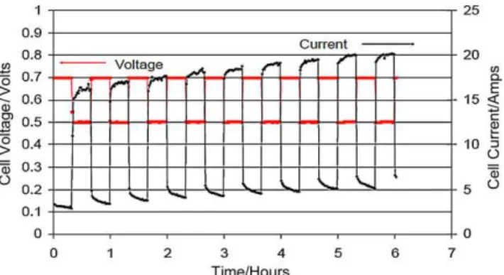
(4)Continuethisloadcyclingprocedureuntilnofurther improve-mentsinperformanceareobserved,oraminimumof6h. Acombinedcurrentcontrolandvoltagecontrolbreak-in proce-durehasalsobeendescribedintheUSFCCsingle-celltestprotocol, asshowninTable2[6].Asimilarthree-stepbreak-inprocedurecan befoundin[21],withaslightdifferenceinthefirstcyclingstep,in whichvoltagecyclingwassetat30minpersetting(0.94–0.6Vat 10stoich,10A)andfollowedbya20Aloadfor4hafterthe three-stepbreak-in.Examplesofperformanceincreaseduringthesecond andthirdstepsarepresentedinFigs.2and3[21].
2.1.2.2. Shortcircuit. Differentfrompotentialcycling,ashort cir-cuitmethodwasreportedbyXieetal.[14].Thismethodservedas partoftheconditioningorpre-conditioningprocess.Aftertheset temperaturesofthecellandlineswereachieved,theanodewas electricallyshortedtothecathodeforafewminutes,followedby aconditioningprocessofcurrentcontrolfor6h.Thisshortcircuit processwasdescribedasintendedtodepletetracesofhydrogen.
Surprisingly,shortcircuitinghasbeenusedastheentire con-ditioningapproachaswell.Sunetal.[2]providedashortcircuit methodtoactivatetheelectrode.Themethodincludesthreesteps: (a) connecttheanodeandthecathodetoshortthecell
(b) supplythestackwithcyclingcoolingwater,fuel,andoxidant (c)adjusttheflowrate.
Fig.2.Voltageandcurrentprofilesduringstep2ofbreak-in,withcyclingbetween 0.7Vand0.5Vfor6h(20mineachsetting).(Celltemperature:60◦C;backpressure:
3.7psig;H2/air:696/1740sccm(fixedflows).)[21].(Imagecourtesyoftheauthor.)
Fig.3.Voltageprofileduringstep3ofbreak-in,withconstantcurrentat10Afor 12h.(Celltemperature:60◦C;backpressure:3.7psig;H
2/air:696/1740sccm(fixed
flows).)[21].(Imagecourtesyoftheauthor.)
Whenthecellorstackisshorted,thecurrentdependsonthe flowrateofthereactants,denotedasthemaximumvalueofthe current,andthecellvoltageisaround0V.Incaseswherereverse voltageforanyofthecellsinthestackexceedsatimelimit,say 30s,adjustthetimesforthelowflowrateandthehighflowrateto ensurethatthereversevoltagetimeremainswithinthereference timeforreversevoltage.Withalowflowrateof1min,ahighflow rateof3min,and7repetitions,thisacceleratedconditioning pro-cesscanbecompletedin30min.Attheendofthisprocess,supply hydrogenataminimumrateandstopsupplyingoxygen.Whenthe cellvoltageisbelow0.1V,stopsupplyinghydrogen.Thus,attheend oftheactivation,eliminatingtheoxygensupplyhelpstodisconnect thewiresafelyandreducethepossibilityofcarboncorrosionatthe cathodeside.Thismethodisadvantageousbecausethevoltageis about0V,whichcanactivateboththemembraneandthecatalyst layer,andtheactivationtimeissignificantlyreducedto1/10ofthe conventionalmethodtime.Thus,hydrogenconsumptionisgreatly reduced,loweringthecostconsiderably.
2.1.3. Temperaturecontrol
Temperaturecontrolhasalsobeenstudiedandreportedto con-ditionaPEMfuelcell.Usually,temperaturecontrolisperformed togetherwithcurrent/potentialcontrolorpressurecontrol.
Fumioetal.[22]havedisclosedafuelcellsystemand tempera-turerelatedmethodtoconditionafuelcellstacktobereadyforuse. Themethodincludestemperaturerise,electricpowergeneration, drypurging,andtemperaturedrop,whicharerepeatedlyexecuted. Thefirststepofthecycleistoraisethefuelcelltoanormal oper-atingtemperature,uponwhichhumidifiedfuelandoxidizergas aresuppliedforagiventimeintervaltogenerateelectricpower. Afterstoppingthegenerationofelectricpowerandsupplyingdry airandfueltothefuelcellstack,residualmoistureispurgedfrom thestack.Afterpurging,thetemperatureofthestackislowered toavaluebelowfreezingpoint,causingmoisturetocondenseina solidpolymermembranetocontainthewater.
AstandardthermalcycleusedtobreakintheMEAwas pre-sentedbyDebefrom3M[23].Thecellisfirstwarmedupto75◦C,
withthehumidificationtemperaturesetat70◦Cforboththeanode
andcathode,andoperatedwithpolarizationcurves orpotential holding.Thenthecelliscooleddowntoroomtemperaturewith gasesoff and liquid water injectedto both anode and cathode for45min.Anotherexamplepresented wasbasedon tempera-turecontroland currentcycling. Thecell isfirstwarmedupto 75◦Cwithoutanyhumidificationoneithersideandwithcurrent
cyclingat0Acm−2for2s,0.1Acm−2for10s,and0.2Acm−2 for
3s.Afteraperformancecheck,morecurrentcyclingat75◦Cis
per-formed.Thenthecelliscooleddownto55◦Cwithcurrentcycling
X.-Z.Yuanetal./JournalofPowerSources196 (2011) 9097–9106 9101
Fig.4.Performanceofan activatedcellatdifferenttemperatures. Nafion112 membrane,Pt1/40:12mgcm−2[24].Acelltemperatureof35◦
C,hydrogeninlet temperatureof45◦
C,andair inlettemperatureof45◦
Cisdenotedhereinas 35/45/45◦
C.Duringactivation,thecellvoltagewassetat0.40–0.60Vformostof thetimetosustainacurrentdensityof1.0–1.5Acm−2,butperiodicallytheloadwas
adjustedinsuchawaythatthecellvoltagewaschangedfromopencircuitvoltage toaslowas0V.
ReproducedwithpermissionfromElsevier.
Qietal.[24–26]providedaneffectiveandfastactivation proce-durebyexposingthefuelcelltoelevatedtemperaturecombined withelevatedpressure.Theprocedurenotonlyismuch shorter thanatraditionalbreak-inprocessbutalsoincreasescatalyst uti-lizationdramatically,especiallyfor electrodeswithlow catalyst loadingsmadeusingsupportedcatalysts[24].Forinstance,after lessthan2hofrunningthecellunderaggressiveconditions,e.g., 75/95/90◦C,thefuelcellperformancecouldbeboosted
dramat-ically. Here, 75/95/90◦C denotes a cell temperature of 75◦C, a
hydrogenhumidificationtemperatureof95◦C,andanair
humid-ificationtemperatureof90◦C(withahydrogenbackpressureof
20psigandanairbackpressureof30psig).Fig.4showstheeffect ofconditioningtemperatureoncellperformance.Ascanbeseen, 75/95/90◦Cyieldsthebestperformanceafteractivation.Thecell
achieved78%activationat0.70Vand93%activationat0.40Vafter aslittleas5min.After30min,thecellachieved87%activationat 0.70Vand97%activationat0.40V.After60min,thecellachieved 93%activationat0.70Vand100%activationat0.40V.After90min, thecellachieved100%activationat0.70Vtoo.
Theyfoundthatunderelevatedtemperature,thecurrent den-sityatcertaincellvoltagescouldbedoubledafterthisactivation procedure, and the activation could be completed extremely quickly,withmostofitachievedinthefirstfewminutes.Itwas proposedthattheactivationprocessincreasescatalystutilization byopeningmany“dead”regionsinthecatalystlayer.Althougha protonconductorsuchasNafionismixedintoacatalystlayerto makeitconductprotonsinthreedimensions,manyofthecatalyst sitesarenotavailableforreactionforvariousreasons:(1)the reac-tantscannotreachthecatalystsitesbecausethelatterareblocked, (2)Nafionnearthesecatalystsitescannotbeeasilyhydrated,or (3)anionicorelectroniccontinuityisnotestablishedwiththese sites.Whenafuelcellisoperatedatelevatedtemperatureand pres-sure,manyofthese“dead”regionsare“opened”andthenbecome active[24].
Theactivationeffectalsoprovedtobelong-lasting;forexample, theactivatedelectrodelastedforabout4weeks.Duringthistime period,thecellwaseitheroperatedcontinuouslyforafewdays orshutdownforoneorseveraldays,thenstartedthenextday, andatonetime,thecellwasfrozenat−17◦Cfor3days.Inthese
4weeks,theperformancefluctuatedslightlybutthetrendshowed verylittledecrease.Itwasbelievedthatthefluctuationwasdueto watermanagementratherthanactivationloss[24].
Furtherstudy[24]shows thatunderelevatedtemperaturea variety of supported catalysts can allbe fully activated within severalhours,althoughdifferentcatalystsmayneeddifferent acti-vationtimes.Generallyspeaking,theimprovementinperformance afteractivationisgreaterforcatalystswithlowerPtcontentona support.Theactivationprocedureisalsoapplicabletoelectrodes madeusingunsupportedcatalystssuchasPtblack,buttheincrease inperformanceisnormallylessthanforelectrodesmadeusing sup-portedcatalysts.MEAsconsistingofdifferenttypesofmembranes, orthesametypeofmembranebutwithdifferentthicknesses,are allabletobeactivatedquickly.
2.2. Hydrogenevolution/pumping
H2evolution,alsoknownashydrogenpumping,onelectrodesis
aneffectivewaytoimprovePEMfuelcellperformancebymoving hydrogenfromonesideofthemembranetotheother.For exam-ple,toactivatethecathode,hydrogenispassedthroughtheanode andanexternalpowersourceisappliedtothefuelcell,withthe cathodesidehavingalowervoltagethantheanodeside.Hydrogen attheanodeisoxidizedtoformprotons,whicharetransported throughthemembranetothecathode,wheretheyarereducedto formhydrogen.ThereactionsforH2evolutionontheelectrodes
areasfollows:
Fuelcellanode: H2=2H++2e−
Fuelcellcathode:2H+
+2e−
= H2
Overall:H2(anode) =H2(cathode)
As a result of this change, electrode catalyst utilization is increasedandMEAperformanceisimproved[5].Thisisachievedby reducingtheoverpotentialofbothoxygenreductionandmethanol oxidation.Thereductionincathodeandanodeoverpotentialsis thoughttobeduetothechangeintheporosityandtortuosityofthe catalystlayerswhenH2evolvesfromthem,leadingtoanincrease
inthenumberofreactant-catalyst-electrolyte3-phasesites. Qi et al. [27] have conducted an activation procedure that involved hydrogen evolution at the electrode. The detailed hydrogen-evolution/hydrogen-pumpingprocedurewasasfollows. Airatthecathodesidewasreplacedbynitrogen,whiletheanode sidewasfedwithpurehydrogen.Anexternalpowersupplywas usedtogenerateacurrentdensityofca.200mAcm−2throughthe
cell,withhydrogenbeingoxidizedattheanode,andtheprotons transportingthroughthemembranetothecathode,wherethey werereduced.Thisprocedurewascarriedoutatacell tempera-tureof35◦Candlastedfor30min.AfterH
2evolutiononthecell
cathode, thecellperformance wasreevaluatedwithH2 andair.
Asshownin Fig.5,afterhydrogenpumping,anincreaseincell performancewasobserved;thiswasexplainedbythechangein catalystutilization,whichmaybeidentifiedbythefuelcell perfor-mancedifferenceinthelowcurrentdensityregion.Atlowcurrent densities,theperformanceoffuelcellsismainlycontrolledbythe electrodekinetics,whichisdirectlyrelatedtothetotalnumberof reactant-catalyst-electrolytesites.
Apart from hydrogen evolution, a procedure of hydrogen exposure has been patented by Ballard to accelerate fuel cell conditioning[28]. Thebriefexposuretodry, ambient tempera-turehydrogen appearedto acceleratetheconditioningprocess, althoughthecellswerestillnotcompletelyconditioned.Onetest showedthatafterdry,unheatedhydrogenwaspipedthroughthe stackanodesandcathodesfor5min,immediatelytheaverage volt-ageofthecellsincreasedby20–32mV.Anothertestshowedthat briefexposuretoheatedand humidifiedhydrogen(80◦C, 100%
Fig.5. PerformanceofaH2/airfuelcellbeforeandafterH2evolutiononthecathode.
Catalystloading0.55mgPtcm−2forbothanodeandcathode;temperature70◦
C; ambientpressure;Nafion1135membrane[1].
ReproducedwithpermissionfromElsevier.
RHfor5min)broughtthestackalmosttothenominaloperating voltage(within95%ofnormal).
2.3. COoxidativestripping
Itiswellknownthatcarbonmonoxide(CO)canseriouslypoison aPEMfuelcellduetoitsstrongadsorptionontocatalysts;hence, COhasbeenconsideredanuisanceandobstacletothe develop-mentoffuelcells.Interestingly,aspecialactivationprocedurethat involvesCO wasreportedbyQietal.[29],whereintheyfound thatCOadsorptioncouldbeusedtoactivatePEMfuelcells.Fig.6
comparesperformanceunderconventionalbreak-inandCO oxida-tivestrippingconditions.Ascanbeseen,aftereachCOoxidative strippingprocess,cellperformanceincreases.Theperformances indicatedbycurves2,3,and4areapparentlyhigherthanthecurve 1performance(traditionalbreak-in)intheentirecurrentdensity region,whichmeansthataCO-adsorption/CO2-desorptionprocess
pushedthefuelcellperformanceoverthelimitationofatraditional break-inprocedure[29].Thisshowsthatunderthose experimen-talconditions, three CO-adsorption/CO2-desorption cycleswere
neededtoachievemaximumperformance,whichwasabout29% higherthantheresultobtainedbyatraditionalbreak-inprocedure. Here,theconventionalbreak-inprocedureusespurehydrogen andairasthereactants.Thetestwascarriedoutat35/45/45◦Cfor
morethan4h.Duringthisperiod,thefuelcellwassetataround 0.4Vformostofthetime, andperiodicallythecellvoltagewas scannedfromopencircuittonearly0V.Afterabout3hno appar-entfurtherincreasewasobserved[29].Thedetailedprocedurefor
Fig.6. Comparisonofperformanceunderconventionalbreak-inandCOoxidative strippingconditions[29].
ReproducedwithpermissionfromElsevier.
CO oxidativestripping wasasfollows.Ata cell temperatureof 35◦C, initialadsorptionofCO ontothecatalystsurface was
fol-lowedbypotentialsweepingtooxidizeCOintoCO2.Duringthe
COadsorptionprocess,amixedgascontaining0.5%CO(balanced by99.5%nitrogen)wasusedatthecathodeside,andthecathode voltagewassetat0.50V.Theadsorptionwasallowedtolastfor about30mintoensurefullcoverageofCOonthecathodePt cat-alyst(amuchshorteradsorptiontimecouldbeenough,especially ifahigherCOconcentrationwereused).Thenthemixedgaswas replacedbynitrogentoflushoutofthecathodecompartmentall theCOmoleculesthatdidnotadsorbontothecatalyst.The poten-tialsweepingwascarriedoutbetween0.5and1.0Vatascanrate of30mVs−1.Themainpurposeofcontrollingthecathodevoltage
at0.5VorhigherduringbothCOadsorptionandpotential scan-ningstepswastoavoidhydrogenevolutionbecausethatcanalso activatefuelcells.AfterCOisoxidized,CO2shouldleavethe
cata-lystsurfacereadilybecauseitadsorbsveryweaklyontothecatalyst surface.
2.4. Airbraking
Ballard[30]discoveredthatperformancecouldbeimprovedby brieflydrawingpowerfromthefuelcellintheabsenceofoxidant. Thismethodcanbeusednotonlytoactivateafuelcellafter ini-tialmanufacture,obviatingalengthyactivationprocess,butalso torejuvenateafuelcellfollowingprolongedstorage.Duringthe process,thevoltageofthefuelcellremainsgreaterthanorequal tozero.Performanceimprovementsmaybeobtainedevenwhen thevoltageremainsgreaterthan0.4V.Forexample,afterastorage periodof141days,a47-cellstackwasrejuvenatedbysubjectingit toseveralconditioningcycles.Eachcycleinvolvedshuttingoffthe supplyofairwhilestillsupplyinghydrogentotheanode,and con-nectingthestackacrossaresistoruntilthestackvoltagedropped below2V.Thesupplyofairwasthenrestoredandthestack volt-agerecovered.Eachcycletookabout1mintocompleteandthe stackwassubjectedto5consecutiveconditioningcycles. Signifi-cantperformanceimprovementwasobserved.Thismethodhelps toconditionthefuelcellbecausedrawingcurrentfromafuelcell intheabsenceofoxidantyieldsreducingconditionsatthe cath-ode,resultingfromthehigherconcentrationofhydrogenandlower concentrationofoxidant.Oxidizedspeciescanthusbereduced.
An“airbreak”methodwasalsoreportedbyEickesetal.[31]
torecover the performance of a DMFC cathode. This air break methodconsistedofasequenceofstepsperformedinthe follow-ingorder:(i)stoppingairflowtothecell,(ii)immediatelyswitching celloperationtoconstant-currentmodeusingthesamecurrentas thecurrentgenerated bythefuelcellatthetimeoftheswitch, (iii)restartingairflowassoonasthecellreachesapreprogrammed low-voltagelimit,and(iv)immediatelyreturningtothelifetestin constant-voltagemode.Theresultsshowthattheaveragepower outputofthecelloperatedwiththeairbreakissignificantlyhigher thanthatofthecelloperatedcontinuouslywithoutairpulsing.
2.5. Otheron-lineconditioningmethods
Asidefromtheabovediscussedon-lineconditioningmethods, specialtechniqueslikecirculatinghotwater[32]and supplying areducingagent[33]canalsobefoundinpatents.Fortheformer technique,hotwaterisusedascleaningwatercommunicatedtothe anodeandthecathodeviaahotwatersupplyingsystem.Wateris heatedtoapredeterminedtemperaturetoeconomicallycarryouta cleaningprocessofanelectrolytefilm-electrodestructureinashort time,thenisreturnedtoatanktobecircularlyused.Inthelatter case,activationisachievedbysupplyingareducingagenttoatleast thecathode.Thesereducingagents includehydrogen,hydrogen peroxideaqueoussolution,hydrazine aqueoussolution,and
cit-X.-Z.Yuanetal./JournalofPowerSources196 (2011) 9097–9106 9103
ricacidaqueoussolution,whichhelptoobtainhigh-performance electricbatteryoutput.
2.6. Combinationofstressors
Anyoftheaboveactivationmethodscansignificantlyincrease fuelcellperformance.Itisalsopossibletoacceleratethe condition-ingperiodandthereby improvecellperformancebycombining thesetechniquesinaspecificorder.Qietal.[1]foundthat com-biningtheacceleratedstressorscouldyieldbetterPEMfuelcell performancethanifonlyasingleactivationmethodwasused.For example,carryingouteitherhydrogenevolutionorCOstripping afterelevatedtemperatureandpressurecouldfurtherincreasethe fuelcellperformance.Ifelevatedtemperatureandpressurewere introducedaftereitherhydrogenevolutionorCOstripping,thefuel cellperformancecouldalsobefurtherincreased,butthefinal per-formancewassimilartowhatwasachievedwithonly elevated temperatureandpressure.
3. Off-lineconditioning
Traditionally,fuelcellconditioningisoperatedon-lineby con-nectingthefuelcellintothesystemandcontrollingthevoltage, current,andoperatingconditions.Variousstrategieshavealsobeen reportedtoconditiontheCCMsorelectrodesbeforetheyare assem-bledintothecell/stack.
3.1. ElectrochemicalconditioningoftheMEA
It is generally believed that the membrane hydration level, thenumberofprotonconductionchannels,andthecatalystlayer porosity continue to increase during the conditioning period. Palanichamyetal.[34]proposedanelectrochemicaltechniquefor conditioningtheMEA–consistingofaCCMfabricatedbythedecal processandtwoporousgraphitecurrentcollectorsoneachside– byimmersionindilute(0.50M)H2SO4.Thisisachievedby
main-tainingthepotentialbetweenthelimitsofplatinumoxide(PtO) formationandhydrogenevolutiontocleanthePtsurface,aswell asbycreatingprotonconductionpathwaysandporesinthe cata-lystlayer.Duringthiscleaningprocess,onesideoftheMEAattains apositivepotentialvaluewhereelectrochemicaloxidationofthe impurities,PtOformation,andO2evolutionwilloccur.Apartfrom
chemicaloxidation,theimpuritieswillalsobephysically disen-gagedfromtheelectrodesurfacebytheevolvedO2.Theotherside
oftheMEAattainsanegativepotentialvalue,withH2 evolution
beingthepossiblereaction,whichwillalsocleanthePtsurface. Then,thepolaritiesofthetwosidesareswitchedandthecleaning processiscontinueduntiltheactivesurfaceareaofPtintheMEA reachesareproduciblevalue.
3.2. Steamingorboilingtheelectrode
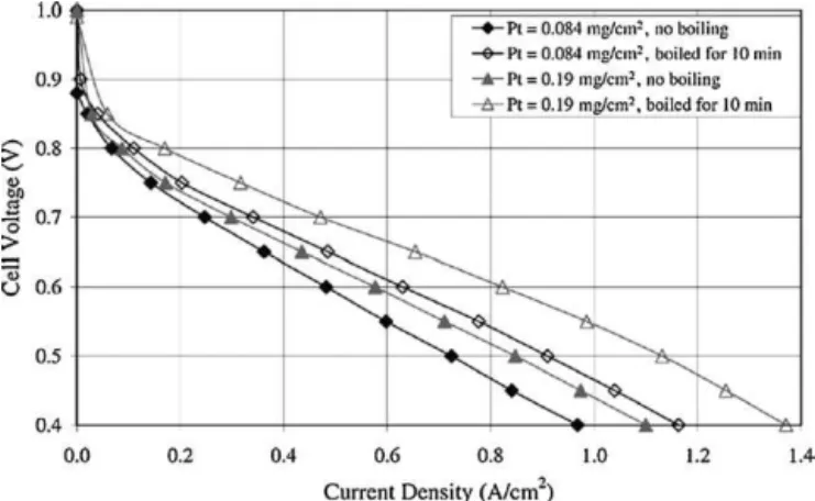
Anotheroff-linemethodistotreatelectrodesorMEAsusinghot waterorsteambeforetheyareassembledintoastack.Qietal.[35]
reportedthattreatmentofelectrodesorCCMsbyeitherboilingin waterorsteaminginahouseholdpressurecookerforasshortas 10mincoulddramaticallyincreasetheirperformancewhentested inPEMfuelcellsafterwards.Theimprovedperformancesareshown inFigs.7and8.Thetreatmentwasonlyappliedtothecathodes becausetheylimit/determinethewholeMEAperformancewhen purehydrogenisusedasthefuel.Whenboiledinwater,the elec-trodesfloatedonitssurface,sothecatalyzedsidewasarranged tofacethewater.Whensteamed,theyeitherfloatedintheliquid waterphaseorweresupportedbyastandsothatonlywatervapour couldbeincontact.
Fig.7. V–Icurvesofelectrodesthatwereboiledfor0and10min,respectively.40% Pt/C[35].
ReproducedwithpermissionfromElsevier.
Fig.8. V–IcurvesofCCMsthatweresteamedfor0,40,and60min,respectively. ThecommercialCCMshaveamembrane25mthickandacatalystloadingof 0.3–0.5mgcm−2oneachside[35].
ReproducedwithpermissionfromElsevier.
Sincesteamingorboilingenhanceselectrodeperformancein thewholevoltageregion,asshowninFigs.7and8,the enhance-mentisbelievedtobeduetoanincreaseinPtutilization.Therefore, oneexplanationproposedbyQietal.[35]wasthatthetreatment increasesthenumberofactivesitesorregionsinthecatalystlayer, leadingtoenhanced catalystutilization.Asweknow,Nafionor anotherionicconductorisalwaysadded totheCLtoensureits three-dimensional activation,and theelectrodesare thendried toremove the solvents.However, Nafionneedstobe hydrated toachievesufficientprotonconductivity.Whentheelectrodesare steamedorboiledinwater,theNafionintheMEAcanachieve com-pletehydration,includingtheNafionmembraneandtheNafionin theCL,leadingtoenhancedMEAperformance.Another explana-tiontheyproposedwasthatsteamingorboilingmaybeableto opensomeotherwise“dead”regionsintheCL.Someregionscould beblockedorenclosedinsuchawaythatgaseousreactantcannot gainaccess,sotheseregionsareeffectively“dead”.Whentreated inhotwaterorsteam,someoftheseregionsareopened,becoming accessibleandactive[35].
AsimilarprocedureofexposingtheMEAtosaturatedsteamat superatmosphericpressure(atleast110kPa)waspatentedby3M
[36]topre-conditiontheMEA.Theprocesstypicallylastsforatleast 10minandmoretypicallyatleast25min,andcanreducethe start-uporconditioningtimerequiredwhentheMEAsarefirstinstalled inafuelcellsystem,improvingcurrentdensityatrelativelyhigh voltage.
3.3. Componentconditioning 3.3.1. Membrane
AsakeycomponentoftheMEA,themembranetransports pro-tonsintheformofanelectrolyteandactsasabarrierbetweenthe anodeandcathodetopreventgaspermeation.Themostcommonly usedmembraneiscomposedofperfluorosulfonicacid(PFSA),such asNafion membrane. For improvedperformance, Nafion mem-braneshouldbeconditionedbeforeuse.Toanalyzeandquantifythe effectofconditioningtechniquesonmembraneperformance, Bar-rioetal.[37]havecarriedoutvariousexperimentswithNafion117 cationexchangemembranes,forexample,atroomtemperature andhighertemperatures.Throughmeasuringthewatercontent (membraneswelling)ofthetreatedmembrane,andtestingthefuel cellassembledwiththetreatedmembrane,includingpolarization curves,impedancespectroscopy,andlinealandcyclic voltamme-tries,theyfoundthatusingacidicconditionsandhightemperatures (around80◦C)toconditionthemembraneobtainedamaximum
powerinafuelcellupto6timesthatofanuntreatedcommercial supply.
3.3.2. GDL
TheGDLisacarbon-basedporoussubstratebetweentheCLand theflowfieldthatenablesgasphasetransport,water transport, electronicandthermalconduction,andmechanicalsupport.The mostcommonlyuseddiffusionmediamaterialfortheGDLiscarbon fiberpaper,madeby,forexample,TorayofJapan,Spectracorpof Massachusetts,andSGLofGermany.Duringcelloperation,thecell iscompressedatacertainpressure.Asaresultofthiscompression, geometricaldistortionoftheGDLthicknesscanoccur.Oneofthe consequencescanbesignificantlossofcompressionpressureinthe fuelcellstack,causinganincreaseincontactresistanceandthereby degradingthefuelcellperformance,particularlywhenhighpower outputisneeded.AnotherconsequenceofcompressingtheGDL materialis anintrusion of thematerial intotheflow channels, whichcausesmaldistributionofreactantgases.Topreventfuelcell compressionlossover time,variousstrategieshavebeen devel-oped.Forexample,abladder-typecompressiondevicehasbeen usedtomaintainaconstantstackcompressionforce;however,this deviceisbulkyandnotusefulforautomotiveapplications. Rapa-portetal.[38]providedamethodforreducing(1)thecompression setoftheGDLduringfuelcelloperationand(2)theintrusionofthe GDLintotheflow-fieldchannels.Theseoutcomeswereachieved byprecompressing/preconditioningtheGDL,viasimulating com-pression before actually assemblingthe GDL into thefuel cell. Thishelped toreduceexcessive and nonuniformintrusion into thechannels,andeliminatedtheneedforfuturerecompressionof thefuelcellstackduetolossofcompressionpressure.Ultimately, higherpoweroutputandmore stableperformance canbethus obtained.
4. Arapidbreak-inforPBIfuelcells
Asdiscussedpreviously,themostcommonlyusedmembranes areNafionmembranescontainingPFSA.Fuelcellsfabricatedwith these membranes usually work below 100◦C. Phosphoric acid
dopedpolybenzimidazole(PBI)membranesweredevelopedforuse atanintermediateoperatingtemperature(>160◦C),andofferthe
sameadvantagesasotherintermediate-andhigh-temperaturefuel celltechnologies(phosphoricacid, solid oxide,and molten car-bonate)intermsof thermalmanagement andtolerancetoward impurities.ButsimilartoNafionfuelcells,PBIfuelcellsalsoneed tobeconditionedinaninitialperiodofoperation,toenable repro-ducibilityandcomparabilityofcellperformance.
Forlow-temperaturePEMfuelcells,single-celltestingprotocols byUSFCC[6]andcellcomponentacceleratedstresstestprotocols byDOE[39]havebeendeveloped.Otherorganizationsthatwork oncelltestingandstandardizationinclude,forexample,theFuel CellTEstingandSTandardisationthematicNETwork(FCTESTNET)
[40]andtheJapanAutomobileResearchInstitute(JARI)[41].Even rapidandreproduciblebreak-inmethodshavebeendevelopedby USFCC[6]aspartofstandardizedtestprotocols,and arewidely studiedbyresearchers,asdiscussedinthisreview.Thesebreak-in methodsarecrucialtoensurereproducibilityandcomparabilityof experimentalresultswithinthefieldofPEMfuelcellresearch. Cur-rently,standardizedtestprotocolsorrecommendationsforrapid break-inofPBIfuelcellsarerarelyfound.
Tingelöfetal.[42]provideddifferenttypesofbreak-in proce-duresforstate-of-the-artPBIfuelcells.Thefocuslayonmethods thatcouldrapidlyandreproduciblyensurestablecellbehaviorfor performanceand contaminationstudiesincells andstacks.The cells wereoperatedat constantcurrent (0.2Acm−2)and 160◦C
betweendifferentstepsintheexperimentsandbetween polariza-tioncurves.
•Galvanostaticbreak-in
A100-hconstantcurrentbreak-inatarelativelylowcurrent (0.2Acm−2)isrecommended.Duringgalvanostaticbreak-in,the
performanceofanMEAincreasesnoticeably. •Potentialcycling
Allstandardizedsingle-celltestprotocolsforlow-temperature PEMfuelcellscontainsomecyclingofthecellvoltage,eitheras cyclingbetweendifferentpotentiallevelsorasrepeated polar-izationcurves.ThismethodwasalsotriedforthePBIfuelcell; however,itseemsthatpotentialcyclingisinthiscasenota suit-ablebreak-inmethod.
•High-temperaturegalvanostaticbreak-in
Inthisexperiment,thecellwasfirstoperatedfor100hat160◦C
and0.2Acm−2.Thenthecelltemperaturewasincreasedto200◦C
whilemaintainingthecurrentdensity.Increasingthe tempera-tureofaPBIfuelcellforalimitedperiodoftimecanbeusedas abreak-inproceduretoavoidverylonggalvanostaticcell break-in.Weknowthatoperatinga PBIfuelcellabovethedesigned temperaturewillinevitablycauseadecreaseinperformance,due toevaporationofH3PO3andconsequentloweringofmembrane
conductivity;thislossofconductivitywilleventuallydegradecell performancetoanunacceptablylowlevel.However,ifaPBIfuel cellisoperatedabovethedesignedtemperatureonlyfora lim-itedperiodoftime,theconsequencesfortheMEAarenotvery severe[42].
5. Reconditioning/cellmaintenance
Areconditioningprocessmayalsobeneededforastackafter a certain storageperiod. Thisreconditioning process shouldbe similartotheconditioningprocedure.Forexample,exposingthe cathodetoa reductant(e.g.,hydrogen) canbeused toactivate afuelcellafterinitialmanufactureandprovidefornormal per-formancelevelswithouttheneedforalengthyinitialoperating period[28].Alternatively,thismethodmayalsobeusedto reju-venate/recondition a fuel cell following prolongedstorage. The methodisparticularlyadvantageousformanufacturingpurposes andcommercialapplications,wherethefuelcellstackspends pro-longedperiodsinactive,yetneedstodelivernormaloutputpower inatimelymanner.
Toavoidreconditioning,severalstrategiesmaybedeployedto preventatemporarylossinperformance.Itisbelievedthat meth-odsthatpreventtheformationofoxidesand/orhydroxidesonthe cathodecatalyst maybeusefulinforestallingperformanceloss. Such methodsinclude applyingapotentialtothefuelcell
dur-X.-Z.Yuanetal./JournalofPowerSources196 (2011) 9097–9106 9105 Table3
Comparisonofon-lineconditioningtimeusingvariousmethods.
Testconditions Examples Conditioningtime(h) References
Currentcontrol Constantcurrentof1Acm−2 6 Xieetal.[14]
Stepcurrentcontrol 25(plus2hOCVforwet-up) Bi[15]
Sequentialcurrentcontrol 7–10 Shanetal.[16]
Potentialcontrol Potentialcycling 6–8 Wengetal.[19]
Sequentialvoltage 3–4 Limetal.[8]
Combinedcurrentandvoltagecontrol IonPower:>6USFCC:19 USFCC[6]
Shortcircuit 0.5 Sunetal.[2]
Elevatedtemperature 75/95/90◦
C <2 Qietal.[24]
Hydrogenpumping Externalpowersupplyof200mAcm−2 0.5 Qietal.[27]
COoxidativestripping 0.5%CO >3(aftera4-htraditionalbreak-in) Qietal.[29]
Airbraking 47-cellstack >5min Vossetal.[30]
ingthestorageperiod(e.g.,from0to0.6V/cell),storingthefuel cellatatemperaturebelowambient(e.g.,belowabout−20◦C),or
storingthefuelcellwithablanketofinertgasonthecathode.For example,a47-cellstackstoredat−20◦Cshowedlittletonovoltage
lossover7monthsofstorageandtesting,whereasastackstored at ambient temperature showed stack voltage losses between about0.1and0.33Vmonth−1over11monthsofstorageand
test-ing.Astackstoredat70◦Cshowedstackvoltagelossesofabout
1.2Vmonth−1overthefirst3months,thenlevelledoffatatotal
stackvoltagelossofabout4Voverthetotal8monthsoftestingand storage[30].
Notonly canreconditioning be avoided bystrategic storage offuelcell stacks,butthenormal conditioningprocessmaybe eliminated if the cathode catalyst is adequately reduced, then maintainedinaninertatmosphereorreducedstateuntil manu-facturingiscomplete.Anatmosphereessentiallyfreeof oxygen andwaterissuitablyinerttomaintainthecatalystinareduced state.The reducing step canalsobe accomplishedby exposing thecathodecatalysttoafluidcomprisingareducingagent(e.g., hydrogengas)[30].
6. Concludingremarks
A newlyfabricatedPEM fuelcell usuallyneedsa condition-ingorbreak-inperiodtomaximizeitsinitialperformance.This paperreviewsvariousmethodstoconditionPEMsinglecellsand stacks,seekingeffectiveacceleratedconditioningtechniquesthat cancompletetheprocessinashorttimeperiod.Thesemethods include on-line and off-line conditioningtechniques,with con-ditioning periods ranging from a couple of hoursto days. The conditioningtimesforon-lineconditioningtechniquesare com-paredinTable3.However,thiscomparisonisrelativelylimited, asdifferentresearchgroupsorcompaniesusetheirownpreferred MEAs.DependingonthetypeofMEAcomponents,theactual con-ditioningtimemayvary.
Comparedwithfuelcelldurabilitystudies,researchonfuelcell conditioningisrelativelylimited. In mostcases,proceduresare givenandresultsarepresentedwithoutdiggingfurtherintothe mechanisms.Asaresult,thereportscontainmorehypothesesthan facts.Mostmechanismsproposedarehypotheticalbecausethey lackdirectexperimentalsupportorconcreteexperimental verifica-tion.Asystematicinvestigationofconditioninganditsmechanisms is still required. Also, the stressorsfor conditioning, which are forthemostpartoperatingconditionsliketemperature,relative humidity,potential,andloadcycles,stronglyaffectthe microstruc-turesoftheMEA,whichinturnwillstronglyaffectthelong-term behaviourand durability of thecell [43],as MEAnanomaterial degradationisheavilyhistory-dependent.Surprisingly,theeffects thatthePEMfuelcellconditioningphasehasondegradationare stillrarelystudiedintheavailableliterature.Inaddition,itmaybe advantageoustopreventthelengthyandcostlyconditioning
pro-cessfromoccurringinthefirstplacebytakingappropriatesteps duringthemanufacturingprocess.
References
[1]Z.Xu,Z.Qi,C.He,A.Kaufman,J.PowerSources156(2006)315–320. [2]Y.Sun,Z.Z.Gao,Z.Z.Yin,Z.X.Li,C.C.Wu,Y.M.Jin,C.Y.Liu,Y.M.Ju,M.H.Jin,
Equipmentsandmethodsforacceleratingtheactivationoffuelcell,Chinese PatentCN101340004A(2009).
[3] M.Murthy,N.T.SisofoIII,C.A.Baczowski,Methodanddevicetoimprove oper-ationofafuelcell,US2006/0166051A1.
[4]DOEHydrogenProgramManufacturingR&DPre-solicitationMeeting,Crystal GatewayMarriott,andpreliminarydraftresearchtopicssubjecttorevision priortoasolicitation,May18,2007.
[5]C.He,Z.Qi,M.Hollett,A.Kaufman,Electrochem.SolidStateLett.5(2002) A181–A183.
[6] USFCC single cell test protocol. Available from: http://www.fchea.org/ core/import/PDFs/Technical%20Resources/MatComp%20Single%20Cell%20Test %20Protocol%2005-014RevB.2%20071306.pdf(accessed24.03.11).
[7]RoadmaponmanufacturingR&Dforthehydrogeneconomy,basedonthe resultsoftheWorkshoponmanufacturingR&Dforthehydrogeneconomy, Washington,DC,July13–14,2005.
[8]T.W.Lim,S.H.Kim,S.Y.Ahn,B.K.Hong,B.K.Ahn,Systemandmethodfor acti-vatingfuelcell,US2010/0129689Al.
[9] R.Hallum,PlugPowerInc.,Preconditioningmembranesofafuelcellstack,US PatentUS6576356B1(2003).
[10]A.J.Appleby,E.B.Yeager,Energy11(1986)137–152.
[11]J.Kim,S.M.Lee,S.Srinivasan,J.Electrochem.Soc.142(1995)2670–2674. [12] X.Ren,M.S.Wilson,S.Gottesfeld,J.Electrochem.Soc.143(1996)L112. [13] M.J.Luo,Z.P.Luo,M.Pan,J.WuhanUniv.Technol.28(2006)499–502. [14]Z.Xie,X.Zhao,M.Adachi,S.Ken,T.Mashio,A.Ohma,K.Shinohara,S.Holdcroft,
T.Navessin,EnergyEnviron.Sci.(2008),supplementarymaterial(ESI). [15] WuBi,Electrochem.SolidStateLett.10(2007)B101–B104.
[16]J.Shan,X.Yan,X.Sun,Z.Hou,P.Qi,P.Ming,Afastactivationmethodforafuel cellstack,ChinesePatent201010010014.3.
[17]J.-H.Kim, H.-I.Lee,B. Bae,H.Y. Ha,Electrochemicalanalysisof the pre-conditioningeffectsonDMFC performance, ECSabstract.Available from:
http://www.electrochem.org/dl/ma/206/pdfs/1949.pdf(accessed24.03.11). [18]M.Gerard,J.-P.Poirot-Crouvezier,D.Hissel,M.-C.Péra,J.FuelCellSci.Technol.
8(2011),021004-1–021004-5.
[19]F.-B.Weng,B.-S.Jou,A.Su,S.H.Chan,P.-H.Chi,J.PowerSources171(2007) 179–185.
[20]Z. Lee, A pre-conditioning method for PEM fuel cells, Chinese Patent 200410096285.X.
[21]TommyQ.T.Rockward,Establishingastandardsinglecelltestingprocedure through industry participation, consensus and experimentation. Avail-able from:http://www.fchea.org/core/import/PDFs/Technical%20Resources/ PresentationonSingleCellTestingProcedure.pdf,2004(accessed24.03.11]. [22]K.Fumio,M.Naoya,S.Ryoichi,NissanMotorCo.Ltd.Fuelcellconditioning
systemandrelatedmethod,EuropeanPatent05004688.7(2005).
[23]M.K.Debe,AdvancedcathodecatalystsandsupportsforPEMfuelcells,2010 DOEhydrogenprogramreview,3Mcompany,June8,2010.
[24]Z.Qi,A.Kaufman,J.PowerSources111(2002)181–184. [25] Z.Qi,A.Kaufman,J.PowerSources114(2003)21–31.
[26]Z.Qi,A.Kaufman,Activationofelectrochemicalcellswithcatalystelectrodes, USPatent6,805,983(2004).
[27]C.He,Z.Qi,A.Kaufm,Electrochemicalmethodtoimprovetheperformance ofH2/airPEMfuelcellsanddirectmethanolfuelcells,USPatent6,730,424 (2004).
[28]B.Giesecke,J.Nengyou,BallardPowerSystemsInc.,Conditioningmethodfor fuelcells,CA2429602A1(2003).
[29] Z.Xu,Z.Qi,J.PowerSources156(2006)281–283.
[30]H.H.Voss,R.H.Barton,M.Sexsmith,M.J.Turchyn,BallardPowerSystemsInc., Conditioningandmaintenancemethodsforfuelcells,CA2429598A1(2003).
[31]C. Eickes, P. Piela, J. Davey,P. Zelenay, J. Electrochem. Soc.153 (2006) A171–A178.
[32]B.Takeshi,I.Tsutomu,I.Masahiro,M.Akihiro,C.Hiroto,K.Masahiro,K. Taka-masa,S.Yasushi,HondaMotorCo.Ltd.,Agingmethodforsolidpolymertype fuelcell,JP2010027431(2010).
[33]M.Koji,S.Shigeru,Samsungelectro-mechanics,activationmethodoffuelcell, fuelbatterycellormembraneelectrodeassemblyforfuelcellactivated,cell stackorfuelcellhavingthem,andfuelcellactivationdevice,JP2007273460 (2007).
[34] K. Palanichamy, A.K. Prasad, S.G. Advan, Off-line conditioning of PEM fuel cell membrane electrode assembly (MEA), in: ECS Abstract,
http://www.electrochem.org/meetings/scheduler/abstracts/214/1091.pdf, 2011(accessed24.03.11).
[35] Z.Qi,A.Kaufman,J.PowerSources109(2002)227–229.
[36]B.P.Anderson,SaintPaul,MN,3MInnovativePropertiesCompany, Precon-ditioningfuelcellmembraneelectrodeassemblies,USPatent7608118B2 (2009).
[37]A.Barrio,J.Parrondo,F.Mijangos,J.I.Lombrana,J.NewMater.Electrochem. Syst.12(2009)87–91.
[38]P.A.Rapaport,Y.-H.Lai,GeneralMotorsCorporation,Gasdiffusionlayer pre-conditioningforimprovedperformanceandoperationalstabilityofPEMfuel cells,USPatent0102006A1(2007).
[39]DOE cell component accelerated stress test protocols for PEM fuel cells. Available from: http://www1.eere.energy.gov/hydrogenandfuelcells/ fuelcells/pdfs/component durability profile.pdf,2007(accessed24.03.11). [40]Fuel cell testing and standardisation thematic network. Available from:
http://ie.jrc.ec.europa.eu/fctestnet/,2006(accessed024.03.11).
[41]H.Tomioka,Y.Hashimasa,N.Yoshimura,M.Akai,S.Watanabe,JARIRes.J.28 (2006)247–252.
[42]T.Tingelöf,J.K.Ihonen,Int.J.HydrogenEnergy34(2009)6452–6456. [43] A.A.Franco,S.-K.Cheah,O.Lemaire,HysteresisphenomenainPEMFuelCells
materials degradation: a multiscale modeling viewpoint.Available from:
http://www.electrochem.org/meetings/scheduler/abstracts/217/0257.pdf
![Fig. 1. A sequential voltage profile for cell conditioning under potential control [8].](https://thumb-eu.123doks.com/thumbv2/123doknet/14131291.469099/4.918.526.814.82.321/fig-sequential-voltage-profile-conditioning-under-potential-control.webp)
![Fig. 4. Performance of an activated cell at different temperatures. Nafion 112 membrane, Pt 1/4 0:12 mg cm − 2 [24]](https://thumb-eu.123doks.com/thumbv2/123doknet/14131291.469099/6.918.75.446.86.316/fig-performance-activated-cell-different-temperatures-nafion-membrane.webp)
![Fig. 6. Comparison of performance under conventional break-in and CO oxidative stripping conditions [29].](https://thumb-eu.123doks.com/thumbv2/123doknet/14131291.469099/7.918.57.429.862.1095/fig-comparison-performance-conventional-break-oxidative-stripping-conditions.webp)