Mechanical concept of the neurosurgical robot 'Minerva'
D. Glauser, P. Flury & C.W. Burckhardt
Institut de Microtechnique, Ecole Poly technique Federate de Lausanne, 1015 Lausanne (Switzerland) (Received in Final Form; March 4, 1993).
SUMMARY
We describe a robot capable of performing all procedures necessary to carry out a complete stereotactic neurosurgical operation under the control and supervi-sion of a surgeon. The operation consists of the introduction of a small probe with diameter 2-3 mm through a hole without trepanation. The robot has been built and is now being tested and evaluated. The accompanying control software as well as various medical probes are either in development or partially tested. The installation will be able to carry out a complete intervention under the surveillance of a computed tomography scanner. In this article we emphasize the design choices required to eliminate gearing backlash in a crucial degree of freedom.
KEYWORDS: Surgery; Neurosurgery; Minerva
1. INTRODUCTION
Our laboratory has been involved in industrial robot design since 1975. We felt that medical applications of robots are of sufficient interest to diversify our work and recently began collaboration with the neurosurgery department of the Centre Hospitalier Universitaire Vaudois (CHUV), the Lausanne University hospital. Interventions in the brain, specifically stereotactic operations, attracted our attention because they are quite common, the instrument manipulations are simple, the working field (head) can be reliably immobilised, and automation of the numerous manipulations is possible.
Neurosurgeons at CHUV defined the medical specifications that a robot system for stereotactic neurosurgery would have to fulfil if it were to perform at an advantage to a human neurosurgeon. At present a physician determines a target point from evaluations based upon computed tomography (CT) images. After the transfer of the patient to the operating theatre, the co-ordinates of the Brown-Robert-Wells (BRW) stereo-tactic frame are set manually.
The main goal of our research is to obtain better safety for the patient by increasing the accuracy and precision of the stereotactic neurosurgery operation, decreasing its duration and providing means to give the surgeon continual access to CT imagery during the operation. The robot is designed to be able to carry out a complete intervention under the surveillance of a CT scanner.
2. STEREOTACTIC NEUROSURGERY
Stereotactic neurosurgery consists of the introduction of a small probe of diameter 2-3 mm through a hole drilled in the skull in order 'blindly' to reach a point located within the brain. This point is determined from CT scan sections and is marked by means of a reference frame fixed rigidly to the patient's head. This operation, achieved without trepanation, is carried out under local anaesthesia and presents no significant trauma to the patient who, being conscious, can give the surgeon sensory information during the intervention.
We were particularly interested in the following stereotactic operations (see Figure 1):
• thalamotomy, used to reduce the tremor due to Parkinson's disease by producing a thermic lesion within one of the thalamic nuclei;
• evacuation of haematomas and abscesses;
• biopsy of intercerebral lesions, to obtain tissue samples for histological examination;
• implantation of a radioactive source for local irradiation of deep tumours; and
• implantation of capsules of cells as a method for limiting the effects of Parkinson's disease.
Stereotactic operations require the use of a stereotactic frame with a reference system such as the BRW frame used at CHUV. As illustrated in Figure 2, this is composed of a base ring fixed to the patient's skull with metal pins. A referential composed of nine carbon fibre bars, visible on CT scanner sections, is put on the base ring. It is then possible to determine the 3-D spatial co-ordinates of a point selected on the 2-D screen of the scanner.
The procedure of stereotactic intervention is as follows. The reference frame is first fixed firmly to the patient's head and scanner sections are made. The co-ordinates of the reference and target points are measured on the scanner images and fed into the control program (see Figure 3). The patient is prepared in a pre-operation room, brought into the theatre and fixed by the base ring to the operating table.
The penetration point is then chosen, sterile drapes are arranged, the five co-ordinates on the BRW frame are set, the three axes of a 'phantom' are set as a security check and the frame is fitted onto the base ring. Once this preparation is complete and verified the surgical intervention is allowed to begin.
probe bone
Fig. 1. Head and trajectory of the probe.
carbon fibre bars
fixation pins of the BRW frame
Fig. 2. BRW stereotactic system with referential.1
Fig. 4. BRW frame.1
the position of the various axes and moving the patient are time-consuming. With the present manual method, two to four hours are required to carry out an entire intervention, from fixation of the stereotactic frame to completion of the operation. It is of interest to note that, in this time period, 80% of the surgeon's time is spent on preparation and only 20% on the actual operation.
3. SPECIFICATIONS OF THE ROBOT INSTALLATION
The manual operations described in the preceding section presume that the probe has reached its target point. The safest way to confirm this would be to make a CT-scanner section when the probe is in its presumed final position. By performing the operation within a CT scanner, the loss of time arising from multiple transfers of the patient can be avoided.
Use of a CT scanner should be restricted in duration so that, in case of emergency, other patients may have access to it. The desired duration of our robotised
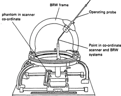
BRW frame phantom in scanner co-ordinate Operating probe Point in co-ordinate scanner and BRW systems
^ Physician ^>
Imaging system Main System
Fig. 5. General plan.
procedure is 30 minutes during which time the operation is expected to be completed.
Our implementation utilises a CT scanner and a BRW reference system. An imaging system, capable of recording scanner sections and processing them so they can serve as an input interface for the physician's commands, is under development. A robot with probes and tools capable of carrying out the entire operation, including skin incision, bone drilling, dura perforation, probe introduction, probe manipulation (i.e., carrying out the medical gesture) and probe exchange, has been designed and built.
Some probes possess their own actuation such as the rotation inherent in the drill or the side outlet electrode. Each probe is a separate unit but has identical mechanical and electrical connections to the probe stocking unit. For safety reasons all probe actuations have been designed to be manually reversible in case of a power failure.
Figure 5 shows a general plan of our robot system.
4. ROBOT GEOMETRY
Initially we considered using a commercially available robot. However, detailed analysis revealed that some
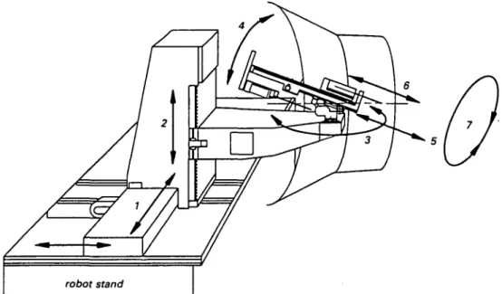
unsuitable. A custom-designed robot was required. Several studies and models were made which enabled us to select a suitable geometric structure for the working environment (see Figure 6) and to ensure the robot's reliability. The use of geometric transformation requires high precision and low tolerance in the manufacture and assembly of the robot components.
To select the geometry we took into account the special nature of the robot tool movements desired, i.e., their dimensions and their working environment (patients' heads).
In a limiting case, the tip of the probe is expected to reach a point located at the centre of the head, some 15 cm from the entry point. Bone drilling is considered to be possible anywhere on a 12 x 11 cm2 surface defined at the top of the head. The gantry of the CT scanner which hosts the operation defines a cone of action within which the robot, its accessories and all movements generated
Fig. 7. Kinematic model.
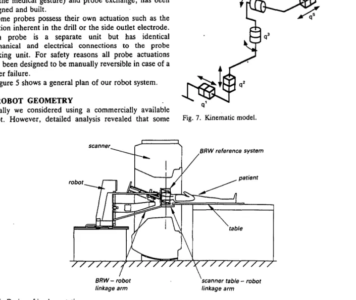
scanner robot BRW reference system patient //y///////// BRW-robot linkage arm
scanner table - robot linkage arm
Fig. 8. Geometry of the robot.
during an operation must be confined. The robot must reach a target point in space with two predefined orientations. Therefore its co-ordinate system must include at least five degrees of freedom. See Figure 9.
The guide tube is immobilised while the intervention tube is inserted into the brain. To achieve this we use two redundant degrees. The fifth degree propels the scalpel and the cart support forward; the sixth degree solely drives the probe holder forward. The two probe orientations, a and fi, have a span of ±30° to reach the target location from an arbitrary point on the entry surface. The mechanical design restricts the angle a clearance to 0-30°. The patient can be operated on facing sideways or down, as may be necessary.
Both robot orientations are arranged as close as possible to the tool-skin contact area, in order to reduce the amplitude of translatory movements. These Car-tesian positioning actuators were placed outside the scanner. The robot is fixed onto a translation guide which ensures its accuracy and stiffness. This passive axis is driven by a linkage arm mounted on the scanner table. Degree No. ql q2 Type linear linear Range 600 mm 300 mm Feature irreversible irreversible
Fig. 10. Example of the robot and CT model.
q' q4 q5 q6 q1 robot stand rotary rotary linear linear rotary linear ±30° 0 to 30° 120 mm 350 mm not limited 500 mm irreversible irreversible irreversible reversible reversible passive skull probe
Fig. 9. Entry and target points.
5. JOINT NO. 4
We discuss in detail the fourth joint (q*). Due to the small space available for displacement within the cone of action of the scanner, we had to design a custom system of gearing for its actuation.
The specifications desired of the joint q* were as follows:
Range: 0 to 30°
Speed: Full cycle to be possible in 20 seconds Safety: This joint needs to be irreversible
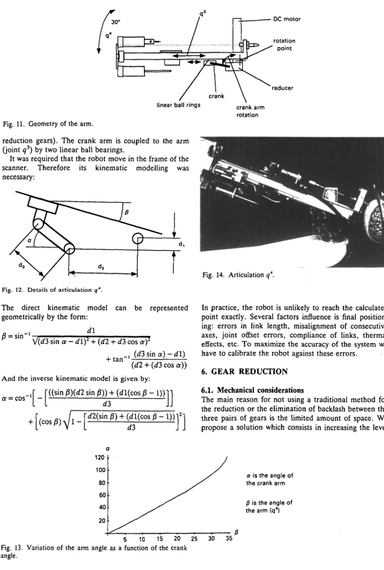
The encoder is mounted on the motor. We use a mechanical reduction of 1080 between the motor and the crank arm (1/60 by worm gear pair and 1/18 by 3 pairs of
rotation point
reducer linear ball rings
Fig. 11. Geometry of the arm.
reduction gears). The crank arm is coupled to the arm (joint q5) by two linear ball bearings.
It was required that the robot move in the frame of the scanner. Therefore its kinematic modelling was necessary:
Fig. 12. Details of articulation q''.
The direct kinematic model can be represented geometrically by the form:
„ . _, d\ r
V(d3 sin a - d\f + (d2 + d3 cos of
_, (d3 sin a) - d\) + t a" {dl + (d3 cos a)) And the inverse kinematic model is given by:
"((sin j3)(rf2 sin p)) + (rfl(cos P - I))1
or = cos '
-crank arm rotation
Fig. 14. Articulation q4.
In practice, the robot is unlikely to reach the calculated point exactly. Several factors influence is final position-ing: errors in link length, misalignment of consecutive axes, joint offset errors, compliance of links, thermal effects, etc. To maximize the accuracy of the system we have to calibrate the robot against these errors.
6. GEAR REDUCTION 6.1. Mechanical considerations
The main reason for not using a traditional method for the reduction or the elimination of backlash between the three pairs of gears is the limited amount of space. We propose a solution which consists in increasing the level
120 100 80 60 40 20 5 10 15 20 25
Fig. 13. Variation of the arm angle as a function of the crank angle.
30 35
a is the angle of the crank arm
f} is the angle of the arm (q4)
of the pitch diameter tolerance from dp(-0.02 to -0.05 mm) to dp (+0.01 to +0.03 mm). The preloading between the two gears will be of the order 2 to 6 ^m.
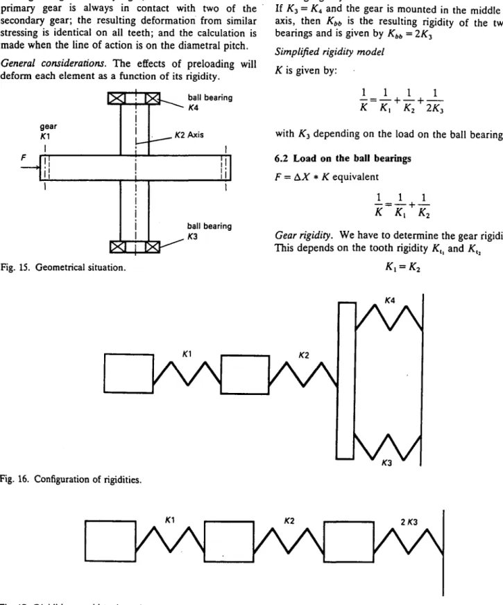
Our system is hyperstatic but can operate as a result of the elasticity in the gear teeth, the axis, and ball bearings. We can estimate the increase in the stressing of the ball bearings and the increase of the pressure between the teeth of the gears using~the following hypotheses: the material of the teeth ensures an infinite rigidity in their line of action, the material of the ball bearing casing is infinitely rigid, at least one tooth of the primary gear is always in contact with two of the secondary gear; the resulting deformation from similar stressing is identical on all teeth; and the calculation is made when the line of action is on the diametral pitch. General considerations. The effects of preloading will deform each element as a function of its rigidity.
gear
f
ball bearing
. K2 Axis
ball bearing
Fig. 15. Geometrical situation.
This overall condition can be analysed by the following expressions:
Ax = preloading considered (5^m in our case), F =
force due to the preloading^ (F = Ax * Kcqujvalenl),
^equivalent = the equivalent rigidity. Rigidity considerations.
where:
/C, = gear rigidity, AT2 = axis rigidity, K3 and £4 = ball
bearing rigidity.
If K3 = K< and the gear is mounted in the middle of the
axis, then Kbb is the resulting rigidity of the two ball
bearings and is given by Kbb = 2K3
Simplified rigidity model K is given by:
K
-L _L
K2 + 2/C3with AT3 depending on the load on the ball bearings
6.2 Load on the ball bearings
F = AX * K equivalent
i
K
K
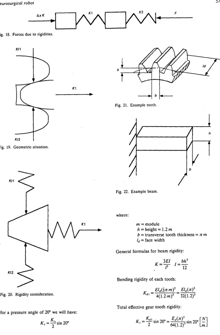
2Gear rigidity. We have to determine the gear rigidity Kx.
This depends on the tooth rigidity Ktl and Ktl
AA AA
Fig. 16. Configuration of rigidities.
kvN
Fig. 17. Rigidities considerations simplified.
2/C3
KA
Fig. 18. Forces due to rigidities.
Kt2
Fig. 19. Geometric situation.
Kt2
Fig. 20. Rigidity consideration.
for a pressure angle of 20° we will have: K , ^ sin 20°
Fig. 21. Example tooth.
Fig. 22. Example beam.
where:
m = module h = height = 1.2 m
b = transverse tooth thickness = n m ld = face width
General formulas for beam rigidity:
3EI bh3
K
~~T
'"IT
Bending rigidity of each tooth: ^Eld{\nmY = rfl
4(1.2 m)3 32(1.2)3 Total effective gear tooth rigidity:
t
Fig. 23. Beam on two supports.
Rigidity of the axis. Rigidity:
_ 4 8 £ / nd4 2
~~T ~64
_48Ejid4 3nEd*rNl Kl~
64/
3" 4/
3L J
Total equivalent rigidity of gears and axis.
1 1 1 „ _ Kj K;
V ~ K K ot ~ k" 4- k
" • t o t 1 ^ 2 / \ [ i i i
\64(1.2): sin 20°
Increasing in the loading on ball bearings. A load on
each ball bearing:
c
-Influence of the preloading on the pressure of the gears.
Fd is the normal load due to the preloading:
F " ~ 2(sin 20°)
Hertzian pressure. To determine Hertzian pressure, we
have to add the normal pressure due to torque transmission and the pressure due to preloading. The Hertzian pressure can hence be estimated as:
P = 0
1 max u-"
cos) at
Fig. 24. Load on the gear.
20° Fd
Fd
Fig. 25. Load on the teeth. where;
w5 = speed of z5
rad
sec (Of, — speed of 26 rad sec
h 19342.1 10"(104.7
nax
V '1510-34210-3sii
E = modulus of elasticity, P = F, + Fu < Ft = tangential
load
Numerical example. We have found that a load of 984 N
(transmitted torque of about 20 Nm) by the gearings resulted in the same Hertzian pressure as would have been given by a preloading of 950 N.
10~3 +304.1 10"3) sin 20° 104.7 10"3 = 1.631109N/m2
The maximum admissible Hertzian pressure value of the material is then 1.70 l09N/m2.
As explained previously, the different choices made when developing the fourth degree of freedom of this robot required considerations uncommon in the mechan-ical design of conventional industrial robots. We mention in particular the maintenance of slow speeds (1 cm/sec), the unusual environment, the safety requirements (axes irreversible), the co-ordinate system of the robot and the problem of cleanliness and sterilisation as examples.
In our case we used a solution that serves to decrease the backlash but which is suitable only because the degree number q* of the robot has a duty-period of
Z6
and will certainly destroy the reducer (limiting Hertzian pressure).
7. FIRST RESULTS
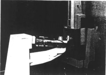
We have carried out a number experiments in order to quantify the quality of mechanics of the robot which we have named 'Minerva'. In our trials we have mechanically linked the extremity of the robot end effector (the tool tip) to a 3-D absolute position measuring system.
Fig. 27. Robot and 3-D absolute measuring system.
To determine the end-tool variation in each of the robot's joints we placed the end effector at an arbitrary point in a known direction and commanded the robot (i.e., the joint axis of interest) to effect displacements backwards in 5 ^m steps a number of times. The play arising from the tested joint was that given by the total number of steps required before the 3-D test system registered a displacement.
Our initial trials have shown a variation of 0.02 mm for each joint. This represents the addition of the backlash, the elasticity present in the robot structure and the imperfections of the measuring system (specified by the manufacturer to be ± 5 ^ m ) . The repeatability of the whole robot was tested using the same 3-D measurement system and was found to be about 0.02 to 0.03 mm.
8. CONCLUSION
In contrast to robots used for manufacturing a medical robot is not designed for optimal dynamic behaviour. Hence we have had no problems with arm mass optimisations. The overriding mechanical constraint has been the external working environment and the rigidity of the robot. This has led to the exclusion of a large
robot is that some links are made from glued aluminium to limit material thickness and from carbon fibre to reduce thermal effects such as dilation.
This article has concentrated upon the mechanical design of the robot. This constitutes only a small portion of our research and development activities.2"5 The installation of Minerva requires surgical tools controlled by the robot control unit and programs to carry out imaging (to process the scanner data), calibration (to determine the robot position in the scanner referential), control of individual tools for each procedure in the operation, supervisory control of the whole application, and effective dialogues to facilitate man-machine communication. All these considerations are subordinate to the necessity for safety at all levels: mechanical, electronic and software.
Currently we have reached the phase of testing and calibrating the robot system. We are now carrying out simulations of full surgical operations. The analysis of these results should determine the effectiveness and safety of the system and should lead to fixing the date of the first tests on human patients some time in the near future.
ACKNOWLEDGEMENT
This project has been financed by the Swiss National Research Foundation.
REFERENCES
1. R.H. Wilkins and S.S. Rengachary, Neurosurgery (McGraw-Hill, New York, 1985).
2. D. Glauser et al., "Configuration of a robot dedicated to
stereotactic surgery" Stereotact. Fund. Neurosurg. 54, 468-470 (1990).
3. D. Glauser et al., "Conception of a robot dedicated to neurosurgery" Proc. ICAR '91 Conf., Pisa (1991) pp. 899-904.
4. P. Flury et al., "Minerva, a robot dedicated to neurosurgery operations" Proc. 23rd ISIR, Oct. 1992, Barcelona (1992) pp. 729-733.
6. N. Villotte et al., "Conception of stereotactic instruments for the neurosurgical robot Minerva" Proc. 14th Annual
Conf. of IEEE Engineering in Medicine and Biology Soc.,
Nov. 1992, Paris (1992) pp. 1089-1090.
ADDITIONAL BIBLIOGRAPHY
A.L. Benabid et al., "Computer-driven robot for stereotactic surgery connected to CT scan and magnetic resonance imaging. Technological Design and preliminary results"
Appl. Neurophysiol. 50, 153-154 (1987).
R.F. Young, "Application of robotics to stereo-tactic surgery"
Neurosurg. Res. (June, 1987).
Y.S. Kwoh et al., "A new computerized tomographic-aided stereotaxis system" Robotic Age (June, 1985).
5. Blond et al., "L'exploration ste're'otaxique des tumeurs ce>6brales" Medecine et Hygiene 48, 1608-1614 (1990).