Publisher’s version / Version de l'éditeur:
Vous avez des questions? Nous pouvons vous aider. Pour communiquer directement avec un auteur, consultez la première page de la revue dans laquelle son article a été publié afin de trouver ses coordonnées. Si vous n’arrivez pas à les repérer, communiquez avec nous à PublicationsArchive-ArchivesPublications@nrc-cnrc.gc.ca.
Questions? Contact the NRC Publications Archive team at
PublicationsArchive-ArchivesPublications@nrc-cnrc.gc.ca. If you wish to email the authors directly, please see the first page of the publication for their contact information.
https://publications-cnrc.canada.ca/fra/droits
L’accès à ce site Web et l’utilisation de son contenu sont assujettis aux conditions présentées dans le site LISEZ CES CONDITIONS ATTENTIVEMENT AVANT D’UTILISER CE SITE WEB.
Surface & Coatings Technology, 329, pp. 232-243, 2017-09-21
READ THESE TERMS AND CONDITIONS CAREFULLY BEFORE USING THIS WEBSITE.
https://nrc-publications.canada.ca/eng/copyright
NRC Publications Archive Record / Notice des Archives des publications du CNRC :
https://nrc-publications.canada.ca/eng/view/object/?id=e373fcaa-9aec-4997-a507-db06e9b15316 https://publications-cnrc.canada.ca/fra/voir/objet/?id=e373fcaa-9aec-4997-a507-db06e9b15316
NRC Publications Archive
Archives des publications du CNRC
This publication could be one of several versions: author’s original, accepted manuscript or the publisher’s version. / La version de cette publication peut être l’une des suivantes : la version prépublication de l’auteur, la version acceptée du manuscrit ou la version de l’éditeur.
For the publisher’s version, please access the DOI link below./ Pour consulter la version de l’éditeur, utilisez le lien DOI ci-dessous.
https://doi.org/10.1016/j.surfcoat.2017.09.052
Access and use of this website and the material on it are subject to the Terms and Conditions set forth at
Cold spray of mixed metal powders on carbon fibre reinforced polymers
Elsevier Editorial System(tm) for Surface and Coatings Technology
Manuscript Draft
Manuscript Number: SURFCOAT-D-17-01863R1
Title: Cold spray of mixed metal powders on carbon fibre reinforced polymers
Article Type: Full Length Article
Keywords: Cold spray; Mixed metal powders; Carbon fibre reinforced polymer; Metallization of polymers
Corresponding Author: Dr. Hanqing Che,
Corresponding Author's Institution: McGill University First Author: Hanqing Che
Order of Authors: Hanqing Che; Xin Chu; Phuong Vo; Stephen Yue
Abstract: Metallization of polymers and polymer composites has attracted interest recently. Cold spray is an emerging coating method, but direct cold spray of metals on carbon fibre reinforced polymer (CFRP) is
difficult. Previous results show that tin coatings can be cold sprayed on CFRP, but the deposition efficiency is relatively low. In this work, copper and zinc powders were mixed with tin to investigate the effect of mixing on deposition efficiency of the coating. The mixed metal powders were cold sprayed on CFRP with a low-pressure system at various
conditions. Results show that the addition of copper and zinc led to much higher deposition efficiencies compared to the pure tin coating. Based on the results, the deposition mechanism of the mixed metal powders on CFRP is discussed, the effect of mixing powders on deposition efficiency is analyzed and several mechanisms are proposed accordingly.
3610 University St, Rm 2400
Montreal H3A 0C5, Canada
June 25, 2017
Dear Editor,
We would like to submit our manuscript entitled “Cold Spray of Mixed Metal Powders on Carbon Fibre Reinforced Polymers” for consideration by Surface and Coating Technology. This manuscript describes original work and is not under consideration by any other journal. All
authors approved the manuscript and this submission.
In this manuscript, we studied cold spray of various mixed metal powders onto CFRP and the
results show that the addition of a second component into tin powder may largely increase the
deposition efficiency. This manuscript is a good supplement to our previous work of cold spray
of single-component powders onto CFRP (https://doi.org/10.1016/j.surfcoat.2017.01.083). The
results in this manuscript are likely to be of great interest to the researchers and engineers in the
area of cold spray as well as metallization of CFRP.
Please address all correspondence concerning this manuscript to me at
hanqing.che@mail.mcgill.ca.
Thank you!
Sincerely,
Hanqing Che
List
of changes and replies to the reviewer’s comments
Reviewer #1:
1. It was found in this work that a number of factors may affect the deposition behavior of
mixed powders, e.g. the density, hardness, morphology, etc., as discussed in Section 4.5.
However, it is uncertain, at the current stage, that which factor may play the most important role.
In fact, it is indeed possible that different factors may have different importance in different
mixed binary systems. This article attempted to point out those factors that may play a role,
while we agree that future work is indeed needed to determine the importance of those factors in
different mixed systems.
2. As suggested by the reviewer, the experimental method and results of conductivity
measurement of the coatings were added into Sections 2 and 3 (new sub-sections 2.3 and 3.4,
and new Figs. 7 and 8 added), highlighted in light blue. The effect of post-spray annealing on
conductivity was also assessed. These added contents are also enclosed at the end of this letter.
On the other hand, since the current work focused on DE, the as-sprayed coating
thicknesses vary significantly. For adhesion test, it has been proved that coating thickness affects
the adhesion strength, so it is necessary to spray coatings with similar thickness so that
reasonable comparison can be made with regard to the bonding strength. Nevertheless, we agree
that the effect of mixing powders on adhesion strength is important, so this has been added into Section 5 as a comment on future work: “Last but not least, it is needed to examine the effect of mixing powders on the coating/substrate adhesion strength”.
3. The following has been added to the last paragraph in Section 1: “The deposition efficiency was measured at each condition and the electrical conductivity of the composite coatings was evaluated.”
4. The previous Figs. 7 and 8 are now numbered Figs. 9, and 10, respectively.
Added subsections and figures:
2.3. Electrical conductivity measurements
The electrical conductivity measurements were performed at École Polytechnique de
Montréal by using the four-point resistivity/conductivity measurement method [25]. Before the
measurements, the as-sprayed top surfaces were slightly ground with 1200# grit sandpaper to
remove the loose particles and obtain flat surfaces. For each sample, the measurements were
taken at three different locations, and the average was taken. The pure tin coating cold sprayed at
300°C and 60 psi in the previous work [12] was also measured for comparison.
To examine the effect of post-spray annealing on the electrical conductivity, several
small sections of various Sn-Cu coatings cold spayed at 300°C and 60 psi were annealed at
200°C in a box furnace for three durations, 1 h, 7 h, and 12 h. The top surfaces of the coatings
were slightly ground with 1200# grit sandpaper to remove the superficial oxide layer before
conductivity measurements. After the measurements, the samples were cross-sectioned, prepared
as per metallographic samples and characterized with a Hitachi SU 3500 SEM.
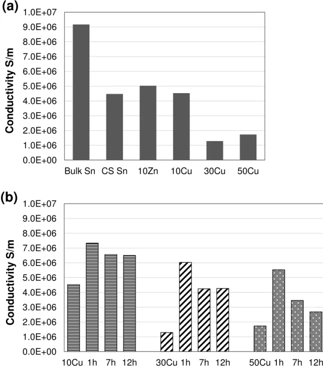
The measured conductivities for various coatings cold sprayed at 300°C and 60 psi are
presented in Fig 7a. All the measurements on one sample are within 7%. The conductivity of
bulk tin is included in Fig 7a as a benchmark. It can be seen that the cold sprayed tin coating is
approximately 49% as conductive as bulk tin, indicating the bonding in the cold-sprayed state is not as conductive as the “100%” metallic bonding in the bulk material. The 10Zn coating exhibits a higher conductivity than the pure tin coating. For the Sn-Cu coatings, the conductivity
of the 10Cu coating is comparable to the cold sprayed tin coating, although the mixed coating is
not fully dense. In contrast, the 30Cu and 50Cu coatings exhibit much lower conductivity,
despite the fact that copper is several times more conductive than tin. In general, the addition of
the more conductive copper into tin did not increase the overall conductivity, but led to a
decrease instead, and the rule of mixtures is obviously not applicable for predicting the electrical
conductivity of the mixed coatings. The decrease may be caused by the porosity and the
increasing number of Cu/Sn interfaces in the coating, which may both behave as the barriers for
electrons. However, the conductivity of the 30Cu coating is lower than that of 50Cu, probably
due to the near-surface defects in the 30Cu coating (Fig. 5b). The conductivities of the 30Cu and
50Cu coatings cold sprayed at 350°C and 60 psi (not shown) are lower than their respective
counterparts at 300°C.
Fig 7b shows the comparison of conductivity before and after annealing in various Sn-Cu
coatings cold sprayed at 300°C and 60 psi. All the measurements on one sample are within 7%.
For all three compositions, the annealing treatment rendered more conductive coatings,
regardless of the annealing time. The conductivity in all three coatings first increased
significantly (62% in 10Cu, 367% in 30Cu and 220% in 50Cu) after annealing for 1 h, followed
annihilation of the defects in the coating and sintering. In general, a higher copper content tends
to lead to a larger increase in conductivity after annealing. The 10Cu coating annealed for 1 h
possesses the highest conductivity, which corresponds to 80% as conductive as bulk tin. For all
the Sn-Cu coatings annealed under the same condition, the higher the copper content, the lower
the conductivity. Similar to the as-sprayed state, the addition of the more conductive copper did
not improve the overall conductivity of the mixture coating, indicating the Cu-Sn boundaries are
not beneficial to electron flux.
The BSE images showing the cross-sectional microstructures of the annealed Sn-Cu
coatings are shown in Fig. 8. For the 10Cu coating, annealing for 1 h did not significantly alter
the microstructure, as shown in Fig. 8a, although it still shows some signs of diffusion since
there exists a grey layer between the bright tin matrix and the dark copper particles. After 7 h
annealing, Fig. 8b shows that significant diffusion took place, as the grey layer grew larger and
the copper particle shrank. The grey phase is the Cu6Sn5 intermetallic phase, according to the
EDX analysis (38.6 wt. % Cu). Between the copper core and the Cu6Sn5 intermetallics, there is a
thin and dark grey layer of Cu3Sn intermetallics (60.5 wt. % Cu), which is indicated by the black
arrow in Fig. 8b. The emergence of the Cu6Sn5 and Cu3Sn intermetallics agrees with the
equilibrium phase diagram [26]. When annealing for 12 h, the copper cores continued shrinking
and totally disappeared at many places while the Cu6Sn5 and Cu3Sn intermetallics kept growing,
only few smaller copper cores left in the coating, as shown in Fig. 8c. The two intermetallic
phases, Cu6Sn5 and Cu3Sn, are much less conductive than copper [27]: Cu3Sn is 15% as
conductive as copper and Cu6Sn5 is 8% as conductive as copper and only 58% as conductive as
formed, decreasing the conductivity. After 7 h, the amount of the Cu6Sn5 did not increase much,
so that the conductivity remains almost unchanged in 10Cu from 7 h to 12 h in Fig. 8.
As for different copper contents, the cross-sectional microstructures of the 10Cu, 30Cu
and 50Cu coatings after annealing at 200°C for 7 h are shown in Figs. 8 d, e and f, respectively.
It can be seen that the amount of Cu6Sn5 after 7 h annealing increases with the increasing copper
content. For the 10Cu coating, it can be seen in Fig. 8d that the Cu6Sn5 phase is distributed as
islands in the coating, and tin is still the matrix; for the 30Cu coating shown in Fig. 8e, the
Cu6Sn5 phase accounts for more than half of the coating in volume, whereas the residual copper
cores and tin account for the rest; in the 50Cu coating, the less conductive Cu6Sn5 intermetallics
further grew and formed a continuous network, whereas the original tin matrix largely shrank
and became isolated, as shown by the bright area in Fig. 8f. In general, the coating with a higher
Cu content (up to 50 wt. %) has a larger amount of the less conductive Cu6Sn5 intermetallics
Fig. 7. Electrical conductivity measurements for (a) various coatings cold sprayed at 300°C, 60
psi and (b) various Sn-Cu coatings before and after annealing at 200°C for different durations. 0.0E+00 1.0E+06 2.0E+06 3.0E+06 4.0E+06 5.0E+06 6.0E+06 7.0E+06 8.0E+06 9.0E+06 1.0E+07
Bulk Sn CS Sn 10Zn 10Cu 30Cu 50Cu
C
o
n
d
u
cti
v
ity
S/
m
(a)
0.0E+00 1.0E+06 2.0E+06 3.0E+06 4.0E+06 5.0E+06 6.0E+06 7.0E+06 8.0E+06 9.0E+06 1.0E+0710Cu 1h 7h 12h 30Cu 1h 7h 12h 50Cu 1h 7h 12h
C
o
n
d
u
cti
v
ity
S/
m
(b)
Fig. 8. BSE SEM images showing the cross-sectional microstructures of various Sn-Cu coatings
cold sprayed at 300°C and 60 psi after annealing at 200°C: (a) 10Cu 1h, (b) 10Cu 7h, (c) 10Cu
Highlights
Metallic coatings were directly cold sprayed on CFRP.
It is found that mixing metal powders can largely increase the deposition efficiency of the component powders.
The deposition mechanism of the mixed metal powders on CFRP is discussed, and a few mechanisms for the improvement in deposition efficiency are proposed.
1
Cold spray of mixed metal powders on carbon fibre reinforced polymers
Hanqing Che a *, Xin Chu a, Phuong Vo b, Stephen Yue aa, Department of Mining and Materials Engineering, McGill University, Montreal H3A 0C5, Canada b, National Research Council Canada, Boucherville, J4B 6Y4, Canada
Abstract
Metallization of polymers and polymer composites has attracted interest recently. Cold
spray is an emerging coating method, but direct cold spray of metals on carbon fibre reinforced
polymer (CFRP) is difficult. Previous results show that tin coatings can be cold sprayed on
CFRP, but the deposition efficiency is relatively low. In this work, copper and zinc powders were
mixed with tin to investigate the effect of mixing on deposition efficiency of the coating. The
mixed metal powders were cold sprayed on CFRP with a low-pressure system at various
conditions. Results show that the addition of copper and zinc led to much higher deposition
efficiencies compared to the pure tin coating. Based on the results, the deposition mechanism of
the mixed metal powders on CFRP is discussed, the effect of mixing powders on deposition
efficiency is analyzed and several mechanisms are proposed accordingly.
Keywords: Cold spray; Mixed metal powders; Carbon fibre reinforced polymer; Metallization of
polymers
* Corresponding author, hanqing.che@mail.mcgill.ca , Tel. +1 514.778.5754, Fax. +1 514.398.4492.
*Manuscript
2
1. Introduction
Metallization of polymers and polymer composites, e.g. carbon fibre reinforced polymer
(CFRP), has attracted substantial interest recently [1-5]. Among a variety of approaches, cold
spray is an emerging coating method and a number of explorations have been reported [4, 6-11].
Direct cold spray of metal powders on various polymeric substrates is usually difficult and
erosion of the substrates has been reported, by a number of researchers, to be the key obstacle [6,
7, 9]. Nevertheless, few successful deposition results have been reported when spraying tin onto
the polymeric substrates [4, 9, 12]. This may be attributed to the low critical velocity as well as
the low melting point of tin [12]. However, since the deposition efficiency (DE) of pure tin on
CFRP is relatively low [12], further endeavors are required to improve the deposition efficiency
and make the process more economically favorable.
In conventional cold spray, the feedstock powder is usually single-component powder
[13]. In the past few years, cold spray of mixed powders has been investigated. In general, mixed
powders are used for two main reasons, to improve the cold sprayability of the powder and to
fabricate intermetallic or composite coatings. For the former, it has been found that mixing
powders can improve the cold sprayability (i.e. increase DE, decrease porosity, etc.) of the
component powders as well as the coating/substrate adhesion. This is usually accomplished by
adding a ceramic component into a metal powder (e.g. adding alumina into aluminum) [14-17],
but Yue et al. [18] have found that mixing two metal powders can also result in similar results.
On the other hand, cold spray of mixed powders has also been used to fabricate composite
coatings (e.g. Al/SiC) [19, 20] and intermetallics, especially those that may otherwise experience
severe oxidation or decomposition when spraying with other high-temperature thermal spray
3
In this work, mixed metal powders were cold sprayed on CFRPs. The reasons for
studying mixed powders are as follows. First, it is desired to improve the DE of tin on CFRP by
mixing tin with other metal powders. Moreover, given the cold-sprayed coating in this work is
primarily for lightning strike protection [12], mixing tin with a more conductive metal (e.g.
copper, zinc) may potentially increase the overall conductivity of the coating (conductivity results
are not reported in this article). Various Sn-Zn and Sn-Cu mixed powders were cold sprayed onto
CFRP at various conditions with a low-pressure cold spray system. The deposition efficiency was
measured at each condition and the electrical conductivity of the composite coatings was
evaluated. The deposition mechanism of the mixed powders on CFRP is discussed. The effect of
mixing powders on the deposition efficiency of the feedstock powder is analyzed, and several
mechanisms are proposed accordingly.
2. Experimental methods
2.1. Starting materials and mixing of powders
The starting single-component materials used in this work were commercial-purity tin
(CenterLine, basically spherical), copper (CenterLine, dendritic morphology), and zinc
(CenterLine, irregular shaped) powders, with average particle sizes of 17, 30, and 40 μm, respectively (measured by a Horiba LA-920 laser scattering particle size distribution analyzer).
The scanning electron microscope (SEM) images of the single-component powders are shown in
Figs. 1 a to c. Four different compositions of mixed powders were prepared for cold spray,
namely, Sn-10 wt. % Zn (10Zn), Sn-10 wt. % Cu (10Cu), Sn-30 wt. % Cu (30Cu), and Sn-50 wt.
% Cu (50Cu). The powders were mixed in a metallic can (no additional media, e.g., mixing balls)
with a double-movement powder mixer for one hour at National Research Council Canada,
4
shown in the backscattered electron (BSE) image in Fig. 1d, the two materials did not show
significant contrast, but the zinc particles are slightly larger and more irregularly shaped than the
majority of tin particles. No obvious morphological change or hardening (based on the
indentation test results, not shown) were found in the mixed powders when compared with the
starting powders. The 50Cu powder (not shown) showed similar results as 10Cu (Fig. 1e) and
30Cu (Fig. 1f), with no significant changes in particle morphology or hardness being found.
The substrates used in this work were CFRP panels provided by Bombardier Aerospace
(Montreal, Canada). The CFRP materials consist of a thermosetting epoxy matrix and continuous
carbon fibre reinforcements. Each panel is made of four plies of Cycom 5276-1/G30-500 epoxy
carbon prepreg ([0/90]2s). For the cold spray experiments, sheet sections of dimensions 7 x 7 cm
were used as the substrates. Prior to the cold spray experiments, these sections were degreased
with acetone. No other surface preparation methods were adopted, unlike metal substrates, which
are often grit blasted before cold spray (the CFRP substrates would be eroded during grit
blasting).
2.2. Cold spray
Cold spray experiments were carried out at the McGill-NRC cold spray facility at
National Research Council Canada, Boucherville. Considering the previously successful results
with the single-component tin powder [12], a commercially available CenterLine SST system
was used to perform the low-pressure spray. Nitrogen was selected as the carrier gas, and the
above-mentioned four mixed powders were sprayed at various conditions, which are listed in
Table 1. Only one layer (one pass) was sprayed at all conditions. The powder feeder was set at 1
revolution per minute (RPM), and the actual feeding rate was measured for each powder before
the spray, which is also shown in Table 1. It can be seen that the feed rate varied from 10 to 13
5
variation in feed rate for any given setting. In the previous work on cold spray of pure tin [12],
the nozzle quickly clogged at 325°C; whereas for 30Cu and 50Cu powders in this work, the
nozzle did not clog up to a gas temperature of 350°C, probably because the copper particles
served as “nozzle sweepers” to clear the nozzle. Temperatures above 350°C were not used in this work. It should be noted that previous cold spray of single-component copper powders at the
conditions listed in Table 1 did not generate any deposition [12]; cold spray of single-component
zinc was not performed. Deposition efficiency, which is the weight change of the substrate
divided by the overall weight of powder sprayed during the time that the gun is actually over the
sample, was measured during cold spray. After the cold spray experiments, the samples were
prepared as per metallographic samples and then characterized with a Hitachi SU3500 SEM.
2.3. Electrical conductivity measurements
The electrical conductivity measurements were performed at École Polytechnique de
Montréal by using the four-point resistivity/conductivity measurement method [25]. Before the
measurements, the as-sprayed top surfaces were slightly ground with 1200# grit sandpaper to
remove the loose particles and obtain flat surfaces. For each sample, the measurements were
taken at three different locations, and the average was taken. The pure tin coating cold sprayed at
300°C and 60 psi in the previous work [12] was also measured for comparison.
To examine the effect of post-spray annealing on the electrical conductivity, several small
sections of various Sn-Cu coatings cold spayed at 300°C and 60 psi were annealed at 200°C in a
box furnace for three durations, 1 h, 7 h, and 12 h. The top surfaces of the coatings were slightly
ground with 1200# grit sandpaper to remove the superficial oxide layer before conductivity
measurements. After the measurements, the samples were cross-sectioned, prepared as per
6
3. Results
3.1. Deposition efficiency
The deposition efficiency results of 10Zn powder at 280°C and 300°C as a function of gas
pressure are shown in Fig. 2. Also shown in the plot, for comparison purpose, are the DE results
of single-component tin at corresponding conditions (DE at 80 and 100 psi at 280°C were not
measured) [12]. At all conditions, deposition was achieved and the DEs at 300°C were much
higher than those of pure tin. In particular, the DE of the mixed powder was more than six times
as large as that of pure tin at 300°C and 80 psi. It can also be seen clearly that at both gas
temperatures, the DE of the 10Zn powder decreased with increasing gas pressure, following
similar trend as the single-component tin powder at 300°C. However, 10Zn showed a slight
decrease in DE from 60 psi to 80 psi but a large one from 80 psi to 100 psi, whereas pure tin
showed a large decrease from 60 psi to 80 psi and a slight one from 80 psi to 100 psi.
The measured DE results of various Sn-Cu powders, in comparison to those of pure tin as
benchmarks [12], are plotted in Fig. 3. It can be seen that, at most conditions, cold spray of the
mixed powder resulted in a much higher DE than pure tin powder. Deposition efficiency of 10Cu
at 280°C increased when the gas pressure was increased from 60 psi to 80 psi. At a gas
temperature of 300°C, except for 50Cu at 60 psi, DE of all the mixed powders decreased with
increasing gas pressure, following the same trend as pure tin at 300°C, a large decrease from 60
to 80 psi followed by a small one from 80 to 100 psi. In particular, DE of 50Cu at 300°C first
increased from 60 psi to 80 psi, and then decreased from 80 psi to 100 psi; at 60 psi, DE of 50Cu
was lower than that of pure tin. The DE curves for 30Cu and 50Cu as well as the pure tin tend to
converge at 100 psi (data fall within 6% to 10%), although the data span much wider ranges at 60
psi (10% to 45%) and 80 psi (7% to 20%). At a higher gas temperature of 350°C, the DE results
7
that at 300°C), then with increasing pressures, the DE curves for 30Cu and 50Cu followed the
same trend as 30Cu and pure tin at 300°C. In general, the addition of copper into tin resulted in
higher DE values than single-component tin, but the higher copper content in the mixed powder
tended to lead to a lower DE (reduce the increment). Note that cold spray of single-component
copper under the same conditions did not generate any deposition [12].
3.2. Microstructure
The SEM characterization results of the 10Zn coating cold sprayed at 300°C and 80 psi
are shown in Fig 4. The light phase in the BSE images is tin and the dark particles are zinc. It can
be seen from Fig. 4a that the coating is relatively thick and dense, but only few zinc particles can
be observed. A zinc particle in the coating is shown in detail in Fig. 4b, in which the zinc particle
is surrounded by many densely distributed, irregular-shaped small particles. Energy-dispersive
x-ray (EDX) spectroscopy analysis indicates these particles are zinc, as shown by the EDX mapping of zinc in Fig. 4c. This microstructure is typical of the “dissolution-precipitation” phenomenon and can be an indication of tin melting in this work, and this will be discussed in
Section 4.1. Figures 4 d and e show the secondary electron images of the top surface of the 10Zn
coating. In general, zinc particles can barely be found at the top surface. A closer look of the top
surface in Fig 4e reveals that there are a large number of small satellites attached to the particles
at the top surface, and some traces of liquid, especially the frozen flowing liquid tracks as
arrowed. This may indicate that tin (partially) melted during the process. A zinc particle at the
coating surface is shown in Fig. 4f. This zinc particle is partially covered by a layer of tin, as
shown by the EDX mapping. At the top surface of the tin layer, signs of liquid can also be
observed.
For Sn-Cu coatings cold sprayed at 300°C and 60 psi, the cross-sectional microstructures
8
distributed homogeneously at the cross-sections. The coating is not fully dense and the pores
basically distributed homogeneously across the cross-sections, with the amount and size of pores
slightly larger near the top surface. The 30Cu coating is relatively dense, but there are a few
lateral defects near the top surface, as shown in Fig. 5b. Copper particles are generally distributed
homogeneously in the coating as well. A copper particle at the cross-section is shown in detail in
Fig. 5c. The copper particle is tightly surrounded by tin, and a number of small particles, with diameters generally smaller than 0.5 μm, exist in the adjacent area of the copper particle. At the copper particle surface, especially the top surface (facing the succeeding layer), there are a
number of “bulges”, as arrowed. Energy-dispersive x-ray spectroscopy analysis of the small particles near copper as well as the bulges at the copper surface indicates these are Cu6Sn5
intermetallics [26]. Similar to Fig. 4b, this microstructure is typical of the “dissolution-precipitation” phenomenon. The interface between the 30Cu coating and the CFRP substrate is shown in Fig. 5d, in which it can be seen that the Sn-Cu coating achieved good mechanical
interlocking with the substrate, as numerous tin “protrusions” penetrating into the CFRP top surface. For the 50Cu coating, as shown in Fig. 5e, the porosity is relatively low (~1%), with
most porosity existing in the top half of the coating and especially near the top surface. The
dissolution of copper and precipitation of the Cu-Sn intermetallics are observed as well, as shown
in Fig. 5f.
At a higher gas temperature of 350°C, the SEM images of the 30Cu coating are shown in
Fig. 6. The coating is relatively dense, with a few pores and defects existing near the top surface
and near the copper particles close to the coating/substrate interface, as shown in Fig. 6a. Copper
particles are generally distributed homogeneously in the coating, but can be rarely seen near the
top surface. At the top of the coating, a couple of irregularities (circled) can be observed. The
9
being surrounded by numerous intermetallics precipitates in the adjacent tin matrix. The
dissolution process of copper was well preserved during cooling, especially at the top of the
copper particles. Due to the higher temperature, the intermetallic precipitates are relatively larger
than those in Fig. 5c (the two images are not at the same magnifications). At the top surface, as
shown in Fig. 6c, a number of large leaf-shaped clusters can be found, which correspond to the
clusters observed in Fig. 6a. The reason for the formation of these clusters is unclear, but may be
a combined effect of particle melting and bouncing. A higher-magnification image of the top
surface is shown in Fig. 6d, showing signs of massive melting such that the originally smooth
surface of the particles (Fig. 1) is totally transformed. The 50Cu coating sprayed at 350°C
exhibits similar microstructural characteristics.
It should be noted that for all the composite coatings, regardless of the amount of the
second component (SC), the SC particles can barely be found near/at the top surfaces or at the
coating/substrate interfaces.
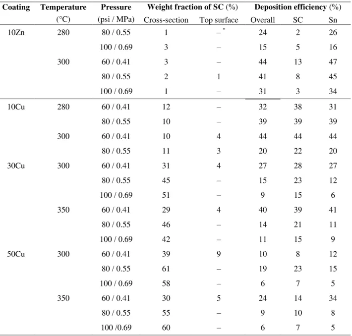
3.3. Retention of the SC materials
The weight fractions of the SC materials were measured by performing area analysis (and
EDX mapping in case there were significant dissolution and diffusion of the SC materials) at the
polished coating cross-sections, and EDX mapping at the top surfaces, and the results are listed in
Table 2. It can be seen that for all mixed powders, the weight fraction of the SC materials
measured at the top surfaces are much lower than those measured at the cross-section, implying
that SC particles were unlikely to adhere to the surface alone without mechanical constraint.
Hereafter, the weight fractions of SC only refer to those measured at the cross-sections. DE
results for the individual components are also listed in Table 2, which were calculated by
10
cross-sections. Those calculated DE results are plotted in Fig. 7, along with the overall DE results
of the mixed powders.
For 10Zn powders, it can be seen from Table 2 that the measured weight fractions of zinc
are generally well below the as-mixed ratio, 10%, indicating poor retention of zinc. It shows in
Fig 7 that at 300°C, DE of tin follows the same trend as the mixed powder while DE of zinc
decreases linearly with increasing pressure, whereas at 280°C, DE of zinc slightly increases at
higher pressure while DE of tin still follows the descending trend of the mixed powder.
On the other hand, the copper retention in the mixed Sn-Cu coatings is much better than
the Sn-Zn coatings. For all three compositions, it can be seen from Table 2 that the composite
coatings generally retained the as-mixed percentage of each component at many conditions.
Interestingly, the copper contents in the composite coatings at high-pressure conditions (80 and
100 psi) are significantly higher than the as-mixed ratio (e.g. 30Cu sprayed at 300°C and 100 psi
contains 51 wt.% copper). Meanwhile, it can also be seen from Fig. 7 that at most conditions
(except 10Cu at 280°C), DE results of copper were on the same level as or below the mixed
powder at 60 psi, then they surpass the mixed powder at 80 psi and stay above those of tin and
the mixed powder till 100 psi. The retention of SC will be further discussed in Section 4.3.
3.4. Electrical conductivity and influence of annealing
The measured conductivities for various coatings cold sprayed at 300°C and 60 psi are
presented in Fig 7a. All the measurements on one sample are within 7%. The conductivity of bulk
tin is included in Fig 7a as a benchmark. It can be seen that the cold sprayed tin coating is
approximately 49% as conductive as bulk tin, indicating the bonding in the cold-sprayed state is not as conductive as the “100%” metallic bonding in the bulk material. The 10Zn coating exhibits a higher conductivity than the pure tin coating. For the Sn-Cu coatings, the conductivity of the
11
fully dense. In contrast, the 30Cu and 50Cu coatings exhibit much lower conductivity, despite the
fact that copper is several times more conductive than tin. In general, the addition of the more
conductive copper into tin did not increase the overall conductivity, but led to a decrease instead,
and the rule of mixtures is obviously not applicable for predicting the electrical conductivity of
the mixed coatings. The decrease may be caused by the porosity and the increasing number of
Cu/Sn interfaces in the coating, which may both behave as the barriers for electrons. However,
the conductivity of the 30Cu coating is lower than that of 50Cu, probably due to the near-surface
defects in the 30Cu coating (Fig. 5b). The conductivities of the 30Cu and 50Cu coatings cold
sprayed at 350°C and 60 psi (not shown) are lower than their respective counterparts at 300°C.
Fig 7b shows the comparison of conductivity before and after annealing in various Sn-Cu
coatings cold sprayed at 300°C and 60 psi. All the measurements on one sample are within 7%.
For all three compositions, the annealing treatment rendered more conductive coatings, regardless
of the annealing time. The conductivity in all three coatings first increased significantly (62% in
10Cu, 367% in 30Cu and 220% in 50Cu) after annealing for 1 h, followed by a slight decrease
with longer durations. The increase can mainly be attributed to the annihilation of the defects in
the coating and sintering. In general, a higher copper content tends to lead to a larger increase in
conductivity after annealing. The 10Cu coating annealed for 1 h possesses the highest
conductivity, which corresponds to 80% as conductive as bulk tin. For all the Sn-Cu coatings
annealed under the same condition, the higher the copper content, the lower the conductivity.
Similar to the as-sprayed state, the addition of the more conductive copper did not improve the
overall conductivity of the mixture coating, indicating the Cu-Sn boundaries are not beneficial to
electron flux.
The BSE images showing the cross-sectional microstructures of the annealed Sn-Cu
12
the microstructure, as shown in Fig. 8a, although it still shows some signs of diffusion since there
exists a grey layer between the bright tin matrix and the dark copper particles. After 7 h annealing,
Fig. 8b shows that significant diffusion took place, as the grey layer grew larger and the copper
particle shrank. The grey phase is the Cu6Sn5 intermetallic phase, according to the EDX analysis
(38.6 wt. % Cu). Between the copper core and the Cu6Sn5 intermetallics, there is a thin and dark
grey layer of Cu3Sn intermetallics (60.5 wt. % Cu), which is indicated by the black arrow in Fig.
8b. The emergence of the Cu6Sn5 and Cu3Sn intermetallics agrees with the equilibrium phase
diagram [26]. When annealing for 12 h, the copper cores continued shrinking and totally
disappeared at many places while the Cu6Sn5 and Cu3Sn intermetallics kept growing, only few
smaller copper cores left in the coating, as shown in Fig. 8c. The two intermetallic phases,
Cu6Sn5 and Cu3Sn, are much less conductive than copper [27]: Cu3Sn is 15% as conductive as
copper and Cu6Sn5 is 8% as conductive as copper and only 58% as conductive as tin. Hence, for
prolonged annealing duration, more of the less conductive Cu6Sn5 intermetallics formed,
decreasing the conductivity. After 7 h, the amount of the Cu6Sn5 did not increase much, so that
the conductivity remains almost unchanged in 10Cu from 7 h to 12 h in Fig. 8.
As for different copper contents, the cross-sectional microstructures of the 10Cu, 30Cu
and 50Cu coatings after annealing at 200°C for 7 h are shown in Figs. 8 d, e and f, respectively. It
can be seen that the amount of Cu6Sn5 after 7 h annealing increases with the increasing copper
content. For the 10Cu coating, it can be seen in Fig. 8d that the Cu6Sn5 phase is distributed as
islands in the coating, and tin is still the matrix; for the 30Cu coating shown in Fig. 8e, the
Cu6Sn5 phase accounts for more than half of the coating in volume, whereas the residual copper
cores and tin account for the rest; in the 50Cu coating, the less conductive Cu6Sn5 intermetallics
further grew and formed a continuous network, whereas the original tin matrix largely shrank and
13
content (up to 50 wt. %) has a larger amount of the less conductive Cu6Sn5 intermetallics after
annealing (at 200°C up to 12 h).
4. Discussion
As shown above, the addition of another metal powder into tin largely increased DE in
most cases, even though, in the case of Cu, the single-component powder could not be
successfully deposited under the same conditions. In this part, the dissolution-precipitation
phenomena that have been observed are discussed, the deposition mechanism of the mixed metal
powders is analyzed, and several mechanisms for the improvement in DE of the mixed powders
are proposed. Moreover, the retention of SC materials is discussed, and the factors that influence
the deposition behavior of mixed powders on CFRP are explored.
4.1. The observed dissolution-precipitation phenomena
The dissolution-precipitation phenomena were observed in various Sn-Zn and Sn-Cu
coatings under different cold spray conditions. Namely, upon impact with the substrate, the SC
particles become surrounded by liquid tin, and begin to dissolve into the enveloping tin melt;
during cooling, small particles (Zn or Cu6Sn5) precipitate from the saturated Sn-SC melt (Figs 4b,
5c, 5f, and 6b). As well, the heterogeneous nucleation sites at the SC particle surface may also be
frozen so the semi-spherical morphology is preserved (Figs. 5c, 5f, and 6b). It should be noted
that the dissolution-precipitation microstructures cannot form by solid-state diffusion, for which
the typical microstructure is diffusion rings or layers. Moreover, tin and zinc are
thermodynamically immiscible [26], so the dissolution of zinc into tin in the solid state is
impossible. Therefore, it confirms that melting of the tin particles occurred when cold spraying
14
of tin at gas temperatures of 300°C and higher with the same system has also been observed
previously [12].
Thermodynamically, precipitations of zinc and Cu6Sn5 intermetallics particles from the
Sn-Zn and Sn-Cu melts, respectively, during cooling are possible, according to the equilibrium
phase diagrams [26]. However, cold spray is a non-equilibrium, highly dynamic process, during
which the melting and cooling of the particles, if any, are rapid. Thus, it is important to examine
the diffusivity of the SC atoms in liquid tin. Table 3 lists the pre-exponential of the Arrhenius
equation, D0, the activation energy, Q, and the calculated diffusion coefficients, D, of the SC
elements at 237°C, five degrees above the melting point of tin. Also included in Table 3 is the
estimated time for an SC atom to diffuse 5 µm in liquid tin, calculated based on the widely used
estimation equation, (x is the diffusing distance, and t the diffusing time) [28]. It can be seen that the diffusivities for both SC atoms are high in liquid tin, e.g. it takes less than 90
milliseconds for an atom to travel 5 micron meters in liquid tin. The high diffusivity provides
enough time for the SC particles to dissolve into molten tin, and thus possibilities for zinc or
Cu6Sn5 to precipitate during the highly dynamic cold spray process.
4.2. The mechanism of deposition of mixed powders
In paper [12], it is proposed that cold spray of metals on CFRP should be considered as a
two-step process, the development of the first layer and the coating build-up. The deposition
windows for each process are defined as vint < v < vero,sub and vcrit < v < vero, respectively, where
vint is the interlock triggering velocity, vero,sub is the velocity leading to significant substrate erosion, vcrit is the critical velocity of the powder (on metallic substrates) and vero is the velocity
leading to first layer erosion/removal. Similar to single-component powder, it is also necessary to
15
work, no zinc or copper particles were found interlocked or in direct contact with the CFRP
surface in all composite coatings, and the interface is Sn/CFRP in nature, so the development of
the first layer proceeded by the same crack-filling mechanism as pure tin [12]. Namely, the
particles impact the substrate and generate some micro-cracks in the surface of the CFRPs, then
the molten/semi-molten tin particles fill in these cracks, interlocking with the substrate and
forming the first layer. Therefore, the criterion for developing the first layer, vint < v < vero,sub, is
still applicable. It is understandable that the SC particles do not bond with CFRP, considering: 1)
copper powder alone cannot be successfully deposited, and 2) both materials are much harder
than tin thus more difficult to deform and fill the cracks under the low-pressure conditions.
As for the build-up of subsequent layers, there are four possible scenarios, namely, tin
impacts on tin, SC impacts on tin, tin impacts on SC, and SC impacts on SC, as discussed below.
a) Tin impacts on tin
When a tin particle impacts on the previously deposited tin particles, the situation is
similar to cold spray of pure tin, thus the criterion for pure tin, vcrit < v < vero, is applicable.
b) SC impacts on tin
When an SC particle impacts on the previously deposited tin particles, there are three
possibilities, depending on the particle velocity. If the SC particle impacts on tin at low velocity,
it is highly likely to bounce away, with at most some tamping effect, due to insufficient kinetic
energy. When the velocity is too high (v > vero), the SC particle may erode the previously
deposited tin layer. At medium velocities, the SC particle may adhere to the previously deposited
tin most likely through mechanically interlocking at low-pressure conditions. It is also possible
that, due to melting, the SC particle penetrates the molten/semi-molten tin, through which
16
rarely observed at the top surfaces in this work, and the weight fractions of the SC materials at
top surfaces were much lower than those measured at the cross-section. This indicates that the SC
particles impact on the previously deposited tin particles at the conditions assessed in this work
do not tend to generate bonding directly.
c) Tin impacts on SC
When a tin particle impacts on an SC particle, it is likely to bond to the SC particle
surface at most conditions performed in this work. It is relatively easy for the molten/semi-molten
tin to spread on and adhere to the SC particle. In particular, when a tin particle impacts an
irregular-shaped copper particle, it may also fill in the spacing within the dendrite-shaped copper
particles, making the retention of the tin particle easier.
More importantly, tin particles impacting on SC may help to retain the SC particles,
which tend to bounce away upon impact. In this work, the SC particles were retained by trapping
due to the subsequent flow of tin particles, as opposed to bonding. If there was no subsequent
impact of tin particles, these SC particles would not be retained in the coating. The retained SC
particle then has an opportunity to react with the molten tin. Indeed, as shown in Fig 5c, the
copper particle was found dissolved into the surrounding tin.
d) SC impacts on SC
When an SC particle impacts on a previously deposited SC particle, due to the lack of
kinetic energy, the particle velocity under the low-pressure condition cannot reach the critical
velocity of SC (pure zinc powder was not cold sprayed in this work, and the critical velocity for
zinc is reported to be 360-380 m/s [29]). Hence, the SC particle would bounce away, or at most
17
the mixed powder, the more likely this scenario. This may help to explain the decreasing overall
DE when cold spraying the mixed Sn-Cu powders with increasing copper content.
4.3. The retention of SC
The retention of SC in the composite coatings in this work varied for different mixed
powders. In general, the SC contents in the Sn-Zn composite coatings were much lower than the
as-mixed ratio, whereas in the Sn-Cu composite coatings the as-mixed ratio can be basically
retained at many conditions and the copper contents are even higher than the as-mixed ratio at
some conditions.
As mentioned above, the SC particles were first retained in the coating through
mechanical constraint (trapping), instead of bonding. It is reasonable to believe that the
morphology of the dendrite-shaped copper particles may play a role in retaining the copper
particles, since retaining one arm of the dendrite-shaped copper particle can retain the whole
particle. Whereas to retain a relatively spherical particle, such as zinc in this work, a large
fraction of its surface has to be covered by tin, otherwise, the particle will escape, contributing to
the low retention rate.
For Sn-Cu powders, it is interesting that at high-pressure conditions the copper contents in
the composite coatings are higher than the as-mixed ratio, and the DE results of copper are higher
than those of tin in the mixed powder or pure tin in the previous work [12], as shown in Table 2
and Fig. 9. This is true for all three Sn-Cu powders at temperatures of 300°C and 350°C, and
pressures of 80 psi and 100 psi. The overturn from 60 psi to higher gas pressures signifies that the
Sn/Cu and or Cu/Sn impacts are better than Sn/Sn impacts at high-pressure conditions. Note that
for pure tin, DE at 300°C and 80 psi decreases as compared to 60 psi due to erosion [12], it is
18
the fact that the overall DE of 50Cu at 300°C and 80 psi is higher than that of 30Cu may be
attributed to fewer Sn/Sn impacts in the 50Cu coating.
4.4. Effect of mixing powders on DE
The DE results for the mixed powders at most conditions are higher than those of pure tin.
Traditionally, a common tool to predict the properties of a hybrid is the rule of mixture (ROM),
which means DE of the mixed powder is given by the arithmetic average of DE of the
components, weighted by their fraction. If compared with the predictions based on the ROM, the
experimental results for all mixed powders are higher than the predictions (e.g. DE of 44% for
10Cu at 300°C and 60 psi compared to a ROM prediction of 14%). There are a number of
possible improving mechanisms, which are discussed below.
i) Tamping
The tamping effect is a widely accepted mechanism when the addition of a harder
component into the metal powders decrease the porosity and increases the overall DE [14].
Although the harder components in conventional cold spray are usually ceramics (e.g. alumina),
the SC metals in this work were also much harder than tin. Besides the conventional tamping, the
impact of the SC particles may also stop any loosely bonded particle from being dislodged,
forcing it to adhere. It is, therefore, reasonable to believe that this effect can be achieved by the
relatively harder SC particles.
ii) Lowering the melting point
It has been found in our previous work [12] that melting of tin contributed to the increase
19
equilibrium phase diagrams [26] show that the existence of SC elements may lower the melting
point of tin, and this is another possible mechanism of DE improvement.
For Sn-Zn powders, the equilibrium phase diagram [26] indicates that increasing zinc
content can lower the melting point of tin, from 232°C for pure tin to 199°C (~13 wt.% Zn).
Indeed, signs of higher degree of melting were observed in the Sn-Zn coatings (Figs 4 d and e),
as compared with pure tin coatings cold sprayed at the same conditions [12]. For Sn-Cu system,
less than 1 wt.% of copper in tin can decrease the melting point by 5 degrees [26]. Given the
considerable difference in DE of pure tin at 290°C and 300°C [12], 5 degrees in the proximity of
melting may play an important role in the deposition of Sn-Cu powders. Experimentally, melting
of tin and dissolution of copper were observed in various Sn-Cu coatings.
Kinetically, it is unclear how fast the SC content may increase in pure tin during the
highly dynamic cold spray process, but once tin melts, the SC particles can fast dissolve into the
melt, indirectly prolonging the melting.
iii) Morphological effect
For Sn-Cu powders, the morphology of the dendrite-shaped copper particles may also
play a role in the DE improvement. Not only that the dendritic copper particles are relatively
easy to adhere to the previous layer, once anchored at the surface, they can also provide more
asperities (tin fills into the gaps in the copper particles) and may behave as cushions, which will
facilitate deposition and alleviate erosion, respectively.
4.5. Deposition behavior and influencing factors
Deposition behavior of single-component tin has been investigated in our previous work,
20
tin [12] as a master curve, which basically consists of two regimes, the ascending part
(deposition-dominant) in the low-velocity regime, and the descending part (erosion-dominant) in
the high-velocity regime. The latter one is a complicated combination of multiple processes,
including the deposition of particles, erosion of the substrate, and erosion of the previously
deposited coating.
Since tin is the primary content, it may be assumed that the deposition behaviors of the
tin-based mixed powders follow that of single-component tin (the particle velocities were not
measured in this work, but it is reasonable to believe the DE-gas pressure curve would follow a
similar trend). When comparing the results in this work to the master curve, it can be seen that
most data fall into the erosion-dominant regime, showing a descending trend of DE with
increasing gas pressure (including 10Zn at both 280 and 300°C, 10Cu at 300°C, 30Cu at 300 and
350 °C, and 50Cu at 350°C as well as at 80 to 100 psi at 300°C). On the other hand, some data
points fall into the deposition-dominant regime and show an ascending trend, including 10Cu at
280°C, 50Cu at 60 to 80 psi at 300°C. It is, therefore, of interest to discuss a few factors that may
affect the shape of the DE-pressure/velocity curve.
The effect of mixing powders depends not only on the SC characteristics of the powder,
but also on the chemistry between the SC element and the primary element (e.g. phase diagram,
etc.). In this section, only the powder characteristics are considered and their influence on the DE
curve is discussed.
Hardness – Both SC materials in this work are harder than the primary tin powder, with copper being the hardest (five times as harder as tin). In general, adding a harder material resulted
in a higher DE in most cases in this work, moving the DE curve upward (as arrow 1 in Fig. 10).
21
effect - when the SC is too hard it may also aggravate the erosion process. Further study is
needed to determine this hardness limit (e.g. mixing tin with iron or harder SC).
The amount of SC – The effect of the amount of SC was assessed for the Sn-Cu system in this work; note that copper alone led to no deposition under the same conditions. The results
suggest that, for SC that does not deposit, higher SC amount would push the DE curve downward
in general (e.g. Cu-Sn at 350°C), or towards the bottom-right direction for the upswing in
particular (e.g. 50Cu at 60 to 80 psi at 300°C showing retarded upswing), as arrow 2 in Fig. 10.
This may be attributed to the increasing probability of SC on SC impact with increasing SC
content.
Morphology – It seems that the addition of a dendrite-shaped powder may contribute to an increase in DE, according to the Sn-Cu results in this work. However, the fact that copper is
harder than tin may also account for part of the increase. Further studies on mixing with spherical
SC, or more SC morphologies, may help to better analyze the influence of SC morphology.
Density – The density of all the component powders are similar in this work, with copper being slightly denser. It is relatively difficult to draw conclusions based on the results in this
work. However, some trial spray with Sn-Al powders (not included) indicates the addition of
aluminum may have some detrimental effects. Further study on mixing tin with low-density
materials (e.g. aluminum, titanium) is advised.
5. Conclusions and comments on future work
Mixed Sn-Zn and Sn-Cu powders with different compositions were cold sprayed onto
CFRPs at various conditions using a CenterLine low-pressure cold spray system. It was found
22
though the second component powder alone cannot generate any deposition onto the CFRPs. The
copper contents in the composite coatings were similar to or higher than the as-mixed ratio,
whereas the retention of zinc was much lower.
During cold spray of mixed powders, there are four possible impacting scenarios, namely,
tin impacts on tin, SC impacts on tin, tin impacts on SC, and SC impacts on SC. When an SC
particle impacts on tin or another SC particle, it tends to bounce away due to insufficient kinetic
energy; whereas if a tin particle impacts on tin or an anchored SC particle, deposition of the tin
particle can generally be achieved.
The possible causes of the improvement in DE include the tamping effect of the relatively
harder SC particles, lowered melting point by the SC elements, and the morphology effect of the
dendrite-shaped copper powder. The dissolution-precipitation phenomena were observed in
various Sn-Zn and Sn-Cu coatings under different cold spray conditions, and they were enabled
by the fast diffusion of zinc and copper in liquid tin.
This work is a first attempt to study the effect of mixing metal powders on their
deposition on CFRP. For future work, it is recommended to mix tin with spherical copper and
compare the deposition results with those in this work, so that the effect of powder morphology
can be determined. It is also of interest to cold spray mixed tin-titanium powders to confirm the
lowering melting point effect. In the tin-titanium system, the melting point increases dramatically
with titanium content. It will then enable the analysis of how the changes in melting point will
affect the cold sprayability. Moreover, mixing tin with low-density metal powders may enable a
look into the effect of SC density on the deposition behavior of mixed powders. Last but not least,
it is needed to examine the effect of mixing powders on the coating/substrate adhesion strength.
23
The authors wish to acknowledge the financial support of the Consortium for Research
and Innovation in Aerospace in Quebec (CRIAQ) and the Natural Sciences and Engineering
Research Council of Canada (NSERC). The industrial partners, Bombardier Aerospace, and the
collaborating university, École Polytechnique de Montréal, are gratefully acknowledged. Mr.
Frédéric Belval from National Research Council Canada, Boucherville and Mr. Martin Gagné
from École Polytechnique de Montréal are acknowledged for their contribution to the cold spray
24
References
[1] G. Archambault, B. Jodoin, S. Gaydos, M. Yandouzi, Metallization of carbon fiber reinforced polymer composite by cold spray and lay-up molding processes, Surf. Coat. Technol. 300 (2016) 78-86.
[2] Z. Guo, L. Sang, Z. Wang, Q. Chen, L. Yang, Z. Liu, Deposition of copper thin films by plasma enhanced pulsed chemical vapor deposition for metallization of carbon fiber reinforced plastics, Surf. Coat. Technol. 307 (2016) 1059-1064.
[3] E. Njuhovic, A. Witt, M. Kempf, F. Wolff-Fabris, S. Glöde, V. Altstädt, Influence of the composite surface structure on the peel strength of metallized carbon fibre-reinforced epoxy, Surf. Coat. Technol. 232 (2013) 319-325.
[4] A. Ganesan, J. Affi, M. Yamada, M. Fukumoto, Bonding behavior studies of cold sprayed copper coating on the PVC polymer substrate, Surf. Coat. Technol. 207 (2012) 262-269.
[5] R. Wang, D. Song, W. Liu, X. He, Effect of arc spraying power on the microstructure and mechanical properties of Zn–Al coating deposited onto carbon fiber reinforced epoxy composites, Appl. Surf. Sci. 257 (2010) 203-209.
[6] J. Affi, H. Okazaki, M. Yamada, M. Fukumoto, Fabrication of Aluminum Coating onto CFRP Substrate by Cold Spray, Mater. Trans. 52 (2011) 1759-1763.
[7] D. Zhang, P.H. Shipway, D.G. McCartney, Cold gas dynamic spraying of aluminum: The role of substrate characteristics in deposit formation, J. Therm. Spray Technol. 14 (2005) 109-116. [8] A. Sturgeon, B. Dunn, S. Celotto, W. O'Neill, Cold sprayed coatings for polymer composite substrate, in: B. Battrick (Eds.) Proceedings of the 10th ISMSE, 8th ICPMSE, Collioure, France, 2006.
[9] R. Lupoi, W. O'Neill, Deposition of metallic coatings on polymer surfaces using cold spray, Surf. Coat. Technol. 205 (2010) 2167-2173.
[10] X.L. Zhou, A.F. Chen, J.C. Liu, X.K. Wu, J.S. Zhang, Preparation of metallic coatings on polymer matrix composites by cold spray, Surf. Coat. Technol. 206 (2011) 132-136.
[11] A. Ganesan, M. Yamada, M. Fukumoto, Cold spray coating deposition mechanism on the thermoplastic and thermosetting polymer substrates, J. Therm. Spray Technol. 22 (2013) 1275-1282.
25
[12] H. Che, P. Vo, S. Yue, Metallization of carbon fibre reinforced polymers by cold spray, Surf. Coat. Technol. 313 (2017) 236-247.
[13] A.P. Alkhimov, V.F. Kosarev, A.N. Papyrin, A method of cold gas-dynamic deposition, Soviet Physics Doklady 35 (1990) 1047-1049.
[14] E. Irissou, J.-G. Legoux, B. Arsenault, C. Moreau, Investigation of Al-Al2O3 cold spray coating formation and properties, J. Therm. Spray Technol. 16 (2007) 661-668.
[15] K. Spencer, D.M. Fabijanic, M.X. Zhang, The influence of Al2O3 reinforcement on the properties of stainless steel cold spray coatings, Surf. Coat. Technol. 206 (2012) 3275-3282. [16] Q. Wang, K. Spencer, N. Birbilis, M.-X. Zhang, The influence of ceramic particles on bond strength of cold spray composite coatings on AZ91 alloy substrate, Surf. Coat. Technol. 205 (2010) 50-56.
[17] H.Y. Lee, S.H. Jung, S.Y. Lee, Y.H. You, K.H. Ko, Correlation between Al2O3 particles and interface of Al–Al2O3 coatings by cold spray, Appl. Surf. Sci. 252 (2005) 1891-1898.
[18] S. Yue, W. Wong, H. Aydin, R. Mongrain, R. Barua, P. Vo, R. Dolbec, Improving Cold Sprayability: Mixed Metal Powders, in: A. McDonald, A. Agarwal, G. Bolelli, A. Concustell, Y.-C. Lau, F.-L. Toma, E. Turunen, Y.-C. Widener (Eds.) International Thermal Spray Conference, Long Beach 2015.
[19] M. Yu, X.K. Suo, W.Y. Li, Y.Y. Wang, H.L. Liao, Microstructure, mechanical property and wear performance of cold sprayed Al5056/SiCp composite coatings: Effect of reinforcement content, Appl. Surf. Sci. 289 (2014) 188-196.
[20] N. Kaur, M. Kumar, S.K. Sharma, D.Y. Kim, S. Kumar, N.M. Chavan, S.V. Joshi, N. Singh, H. Singh, Study of mechanical properties and high temperature oxidation behavior of a novel cold-spray Ni-20Cr coating on boiler steels, Appl. Surf. Sci. 328 (2015) 13-25.
[21] T. Novoselova, P. Fox, R. Morgan, W. O'Neill, Experimental study of titanium/aluminium deposits produced by cold gas dynamic spray, Surf. Coat. Technol. 200 (2006) 2775-2783.
[22] H.Y. Lee, S.H. Jung, S.Y. Lee, K.H. Ko, Alloying of cold-sprayed Al–Ni composite coatings by post-annealing, Appl. Surf. Sci. 253 (2007) 3496-3502.
26
[23] H.-T. Wang, C.-J. Li, G.-J. Yang, C.-X. Li, Cold spraying of Fe/Al powder mixture: Coating characteristics and influence of heat treatment on the phase structure, Appl. Surf. Sci. 255 (2008) 2538-2544.
[24] K.H. Ko, H. Lee, J.O. Choi, Effect of Sn particle size on the intermetallic compound formations of cold sprayed Sn–Ni coatings, Appl. Surf. Sci. 257 (2011) 2970-2977.
[25] F. Smits, Measurement of sheet resistivities with the four-point probe, Bell Syst. Tech. J. 37 (1958) 711-718.
[26] H. Baker, ASM Handbook - Alloy phase diagrams, ASM International, Materials Park, 1992. [27] H.-T. Lee, M.-H. Chen, H.-M. Jao, T.-L. Liao, Influence of interfacial intermetallic compound on fracture behavior of solder joints, Mater. Sci. Eng. A 358 (2003) 134-141.
[28] D.A. Porter, K.E. Easterling, Phase transformations in metals and alloys, Stanley Thornes, Cheltenham, 1992.
[29] T. Schmidt, H. Assadi, F. Gärtner, H. Richter, T. Stoltenhoff, H. Kreye, T. Klassen, From particle acceleration to impact and bonding in cold spraying, J. Therm. Spray Technol. 18 (2009) 794-808.
[30] C.H. Ma, R.A. Swalin, A study of solute diffusion in liquid tin, Acta Mater. 8 (1960) 388-395.
27
Table 1. Process parameters for the low-pressure cold spray of mixed powders.
Powder Temperature °C Gas pressure MPa (psi) Stand-off distance mm
Gun travel speed mm∙s-1 Feeding rate g∙min-1 10Zn 280, 300 0.41, 0.55, 0.69 (60, 80, 100) 18 25 13 10Cu 280, 300 10 30Cu 300, 350 12 50Cu 300, 350 11
28
Table 2. The weight fraction of the SC materials and the calculated DE for each component.
Coating Temperature (°C)
Pressure (psi / MPa)
Weight fraction of SC (%) Deposition efficiency (%) Cross-section Top surface Overall SC Sn
10Zn 280 80 / 0.55 1 – * 24 2 26 100 / 0.69 3 – 15 5 16 300 60 / 0.41 3 – 44 13 47 80 / 0.55 2 1 41 8 45 100 / 0.69 1 – 31 3 34 10Cu 280 60 / 0.41 12 – 32 38 31 80 / 0.55 10 – 39 39 39 300 60 / 0.41 10 4 44 44 44 80 / 0.55 11 3 20 22 20 30Cu 300 60 / 0.41 31 4 27 28 27 80 / 0.55 45 – 15 23 12 100 / 0.69 51 – 9 15 6 350 60 / 0.41 29 4 40 39 41 80 / 0.55 46 – 14 21 11 100 / 0.69 42 – 11 15 9 50Cu 300 60 / 0.41 39 9 10 8 12 80 / 0.55 61 – 19 23 15 100 / 0.69 58 – 6 7 5 350 60 / 0.41 30 5 24 14 34 80 / 0.55 55 – 9 10 8 100 /0.69 60 – 6 7 5 * Not measured
29
Table 3. Diffusion data for zinc and copper in liquid tin (values of D0 and Q taken from [30]).
Element D0 cm2/sec Q cal/mol D at 237°C cm2/sec Time to diffuse 5 µm sec Zn 6.2 × 10⁻⁴ 4880 5.03 × 10⁻⁶ 0.050 Cu 1.8 × 10⁻⁴ 4200 2.85 × 10⁻⁶ 0.088
30
Figure captions
Fig. 1. SEM images showing the single-component powders and mixed powders: (a) Sn, (b) Cu,
(c) Zn, (d) 10Zn, (e) 10Cu, and (f) 30Cu.
Fig. 2. Deposition efficiency of 10Zn mixed powder at 280°C and 300°C, in comparison with
pure Sn powder.
Fig. 3. Deposition efficiency of three Sn-Cu mixed powders at 280°C, 300°C, and 350°C, in
comparison with pure Sn powder.
Fig. 4. SEM characterization of the cold sprayed 10Zn coatings: (a, b) cross-section at 300°C and
80 psi; (c) EDX mapping of Zn of the rectangle area in (b); (d to f) top surface at 300°C and 60
psi, the arrows in (e) are pointing at some frozen flowing liquid tracks and the inset in (f) is the
EDX mapping of the rectangle area in (f).
Fig. 5. Cross-sectional SEM images showing the Sn-Cu coatings cold sprayed at 300°C and 60
psi: (a) 10Cu, (b to d) 30Cu, and (e, f) 50Cu; (c) shows a Cu particle in detail in the 30Cu
coating, with the arrows pointing at the “bulges” at copper surface, (d) shows the 30Cu coating/substrate interface, (f) shows a Cu particle in detail in the 50Cu coating.
Fig. 6. SEM images of the 30Cu coating cold sprayed at 350°C and 60 psi: (a, b) cross-sectional
images, and (c, d) top surface images; circled in (a) are irregularities at the top of the coating.
Fig. 7. Electrical conductivity measurements for (a) various coatings cold sprayed at 300°C, 60
31
Fig. 8. BSE SEM images showing the cross-sectional microstructures of various Sn-Cu coatings
cold sprayed at 300°C and 60 psi after annealing at 200°C: (a) 10Cu 1h, (b) 10Cu 7h, (c) 10Cu
12h, (d) 10Cu 7h at low mag, (e) 30Cu 7h, and (f) 50Cu 7h.
Fig. 9. Plot of DE results of mixed powders (solid lines with markers) and each components
(solid lines for Sn and dashed lines for SC) calculated based on weight fraction measurements.
Figure 1
Figure 2
Figure 3
Figure 4
Figure 5
Figure 6


![Table 3. Diffusion data for zinc and copper in liquid tin (values of D 0 and Q taken from [30])](https://thumb-eu.123doks.com/thumbv2/123doknet/14058346.461013/40.918.116.771.169.273/table-diffusion-data-zinc-copper-liquid-values-taken.webp)
