Publisher’s version / Version de l'éditeur:
Vous avez des questions? Nous pouvons vous aider. Pour communiquer directement avec un auteur, consultez la première page de la revue dans laquelle son article a été publié afin de trouver ses coordonnées. Si vous n’arrivez pas à les repérer, communiquez avec nous à [email protected].
Questions? Contact the NRC Publications Archive team at
[email protected]. If you wish to email the authors directly, please see the first page of the publication for their contact information.
https://publications-cnrc.canada.ca/fra/droits
L’accès à ce site Web et l’utilisation de son contenu sont assujettis aux conditions présentées dans le site LISEZ CES CONDITIONS ATTENTIVEMENT AVANT D’UTILISER CE SITE WEB.
Scientific Reports, 9, 1, 2019-03-05
READ THESE TERMS AND CONDITIONS CAREFULLY BEFORE USING THIS WEBSITE. https://nrc-publications.canada.ca/eng/copyright
NRC Publications Archive Record / Notice des Archives des publications du CNRC :
https://nrc-publications.canada.ca/eng/view/object/?id=b4fa4533-5bed-42a4-89bf-19300ee45783
https://publications-cnrc.canada.ca/fra/voir/objet/?id=b4fa4533-5bed-42a4-89bf-19300ee45783
NRC Publications Archive
Archives des publications du CNRC
This publication could be one of several versions: author’s original, accepted manuscript or the publisher’s version. / La version de cette publication peut être l’une des suivantes : la version prépublication de l’auteur, la version acceptée du manuscrit ou la version de l’éditeur.
For the publisher’s version, please access the DOI link below./ Pour consulter la version de l’éditeur, utilisez le lien DOI ci-dessous.
https://doi.org/10.1038/s41598-019-40497-7
Access and use of this website and the material on it are subject to the Terms and Conditions set forth at
Polarization- and wavelength-agnostic nanophotonic beam splitter
González-Andrade, David; Lafforgue, Christian; Durán-Valdeiglesias, Elena;
Le Roux, Xavier; Berciano, Mathias; Cassan, Eric; Marris-Morini, Delphine;
Velasco, Aitor V.; Cheben, Pavel; Vivien, Laurent; Alonso-Ramos, Carlos
Polarization- and
wavelength-agnostic nanophotonic beam
splitter
David González-Andrade , Christian Laforgue
,, Elena Durán-Valdeiglesias , Xavier Le
Roux , Mathias Berciano , Eric Cassan , Delphine Marris-Morini , Aitor V. Velasco ,
Pavel Cheben , Laurent Vivien & Carlos Alonso-Ramos
High-performance optical beam splitters are of fundamental importance for the development of advanced silicon photonics integrated circuits. However, due to the high refractive index contrast of silicon-on-insulator platforms, state-of-the-art nanophotonic splitters are hampered by trade-ofs in bandwidth, polarization dependence and sensitivity to fabrication errors. Here, we present a new strategy that exploits modal engineering in slotted waveguides to overcome these limitations, enabling ultra-broadband polarization-insensitive optical power splitters with relaxed fabrication tolerances. The proposed splitter design relies on a single-mode slot waveguide that is gradually transformed into two strip waveguides by a symmetric taper, yielding equal power splitting. Based on this concept, we experimentally demonstrate − ± . dB polarization-independent transmission for an unprecedented
9 nm bandwidth ( – nm), even in the presence of waveguide width deviations as large as
± nm.
Silicon-on-insulator (SOI) platforms are becoming established as an enabling technology for next-generation photonic circuits for a wide range of applications, including telecom and datacom applications1–3, radio-over-ibre
systems4,5, bio-sensing6,7, LIDAR8 and absorption spectroscopy9,10, to name a few. Such applications would
ben-eit from the low-cost and large-volume fabrication ofered by existing CMOS facilities as well as from the high density of integration enabled by the high refractive index contrast of SOI platforms. Furthermore, the high modal coninement of Si wire waveguides provides strong light-matter interactions with great potential for exploitation in opto-electronics, sensing and non-linear optical devices11,12. However, the index contrast and
modal coninement of SOI platforms also pose important challenges for the realization of high-performance SOI circuits, including a strong sensitivity to small geometric deviations, strong modal dispersion, and large birefringence between the transverse electric (TE) and transverse magnetic (TM) modes. Hence, SOI circuits typically operate in a single polarization state, within a limited bandwidth and with tight fabrication tolerances. Nevertheless, polarization-independent devices have emerged showing very similar performance for both TE and TM polarizations13. High-performance SOI ibre-chip interfaces have been demonstrated to yield broadband and
high-eiciency coupling with negligible polarization dependence and relaxed fabrication tolerances14–16, but such
performance enhancements are still sought ater in other essential SOI components. Speciically, beam splitters are particularly sensitive to the efects related to high index contrast and tight mode coninement in Si wires and would greatly beneit from achieving ultra-broadband dual-polarization operation.
Over the past few years, several beam splitters with diferent advantages and limitations have been proposed. Directional couplers (DCs) are based on two parallel waveguides separated by a gap, enabling straightforward tuning of the power-splitting ratio by adequately selecting the coupling length. Due to their mode-beating-based operational principle, DCs are intrinsically narrowband in nature and sufer from a low tolerance to fabrication errors and a strong polarization dependence17–19. he constraints on fabrication tolerances have been alleviated
by engineering the excitation of odd and even modes in shallow-etched20 and fully etched DCs21–24, but only
single-polarization operation and dual-polarization operation over a limited bandwidth have been demonstrated.
Instituto de Óptica Daza de Valdés, Consejo Superior de Investigaciones Cientíicas (CSIC), Madrid, , Spain. Centre de Nanosciences et de Nanotechnologies, CNRS, Université Paris-Sud, Université Paris-Saclay, C N, Orsay, , France. École Normale Supérieure Paris-Saclay, Université Paris-Saclay, Cachan, , France. National Research Council Canada, Montreal Road, Ottawa, Ontario, K A R , Canada. Correspondence and requests for materials should be addressed to D.G.-A. (email: [email protected])
Received: 19 July 2018 Accepted: 14 February 2019 Published: xx xx xxxx
www.nature.com/scientificreports
www.nature.com/scientificreports/
Silicon-bent13 and subwavelength-grating-assisted25–28 (SWG) DCs have recently been demonstrated to exhibit
polarization-independent and ultra-broadband behaviour separately, but these approaches are still hampered by a high sensitivity to manufacturing deviations. Alternatively, symmetric Y-junctions or Y-branches have been demonstrated as theoretically lossless splitters29–31. However, their performance is signiicantly degraded in real
fabrication scenarios due to the limited etching resolution when deining the abrupt discontinuity at the branch intersection. Consequently, the broad bandwidth and reduced polarization dependence are maintained, but a comparatively high insertion loss is exhibited. To overcome this limitation, several Y-branch variations32–34
have emerged, showing relatively broad bandwidths. Multimode interference couplers (MMIs)35 exploit the
self-imaging (Talbot) efect to achieve low losses with improved fabrication tolerances but provide only limited bandwidth- and polarization-dependent behaviour. Sub-wavelength engineering has been applied to increase the operational bandwidths of MMIs36,37, but only in single-polarization operation. Other alternatives include
inverse tapers38, star couplers39, adiabatic couplers40 and photonic crystal waveguides41, all of which are limited
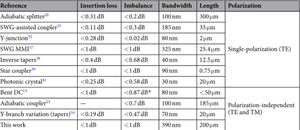
in terms of either operational bandwidth, fabrication requirements or design complexity. Experimental results of aforementioned beam splitters are summarized in Table 1, where it is observed that most of them operate in a single polarization state, usually TE. Only Halir et al. have experimentally demonstrated a device with a band-width broader than 300 nm37. heir subwavelength engineered MMI presents insertion loss and imbalance below
1 dB over a 325 nm wavelength range, in addition to a compact footprint of only 3.25 × 25.4 µm2, but operates
only for TE polarization. On the contrary, polarization-insensitive beam splitters tend to increase the length of the device to attain low insertion loss and imbalance over a broad bandwidth. For example, the device proposed by Xu et al. exhibits a length longer than 120 µm and operates within a 100 nm bandwidth for both TE and TM polarizations simultaneously23, whereas the bandwidth is reduced to only 70 or 80 nm in other devices with more
compact footprints.
In this work, we propose and experimentally demonstrate a new beam splitter concept based on modal-engineered slotted waveguides. his design provides ultra-broadband and polarization-independent operation with relaxed fabrication tolerances. Our experimental results demonstrate a near-ideal transmission of −3 ± 0.5 dB in an unprecedented bandwidth of 390 nm for both the TE and TM polarizations.
Results
he proposed beam splitter, schematically shown in Fig. 1, relies on a single-mode slot waveguide that equally splits the injected power into two output strip waveguides in a wavelength- and polarization-agnostic fashion. Our device comprises three main sections: a strip-to-slot mode converter (section I), a slot waveguide (section II) and a slot-to-strip splitting transition (section III). he single-mode operation of the slot waveguide is of fundamental importance to our device because it mitigates any wavelength-dependent beating between difer-ent waveguide modes, which is the main phenomenon limiting the bandwidths of DCs and MMIs. he adiaba-tic strip-to-slot mode converter ensures the low-loss excitation of the fundamental (TE or TM) slot-waveguide mode42,43, while the symmetry of the slot-to-strip transition ensures equal power splitting between the two
out-put waveguides, independent of the polarization and wavelength. Furthermore, this transition is robust against common under- and over-etching errors, as the latter do not break the structural symmetry, thus allowing the power-splitting ratio to be maintained. Finally, as the slot waveguide already includes a central gap, our transition circumvents any abrupt index discontinuity, minimizing back-relections which are a major source of loss in con-ventional Y-junctions. Figure 1 also shows the electric ield mode proile at each section of our proposed device, obtained via Finite-Diference Eigenmode (FDE) solver.
In our design 220-nm-thick and 450-nm-wide (WI) silicon-wires were used as the input and output strip
waveguides. A buried silicon dioxide layer (BOX) and polymethyl methacrylate (PMMA) upper cladding were assumed, with refractive indexes nSi = 3.476, nSiO2 = 1.444 and nPMMA = 1.481, respectively, at the design
wave-length of 1.55 µm. First, we design the central slot waveguide in section II for single mode operation with no propagating higher order modes44,45. he slot waveguide comprises two narrow silicon waveguides, hereater rails,
Reference Insertion loss Imbalance Bandwidth Length Polarization
Adiabatic splitter20 <0.31 dB <0.2 dB 100 nm 300 µm Single-polarization (TE) SWG-assisted coupler25 <0.11 dB <0.3 dB 185 nm 35 µm Y-junction32 <0.28 dB <0.02 dB 80 nm 2 µm SWG MMI37 <1 dB <1 dB 325 nm 25.4 µm Inverse tapers38 <0.4 dB <0.68 dB 40 nm 12.5 µm Star coupler39 <1 dB <1 dB 90 nm 0.75 µm Photonic crystal41 <0.25 dB <0.58 dB 30 nm 20 µm Bent DC13 <1 dB <0.87 dB* 80 nm <50 µm Polarization-independent (TE and TM) Adiabatic coupler23 — <0.7 dB 100 nm 185 µm
Y-branch variation (tapers)34 <0.19 dB <0.47 dB 70 nm 20 µm
his work <1 dB <1 dB 390 nm 200 µm
Table 1. Experimental performance of state-of-the-art silicon beam splitters including insertion loss, imbalance, bandwidth, device length and polarization operation. Worst performance between TE and TM polarizations is considered for polarization-independent beam splitters. Note: values marked with an asterisk are extracted from either igures or splitting ratio data from the references.
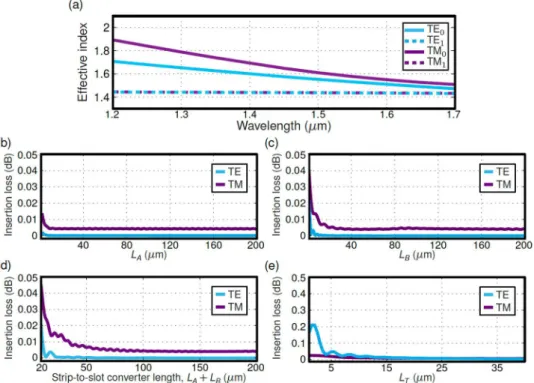
separated by a low refractive index gap. We choose a rail width of WR = 150 nm and a slot width of GS = 100 nm,
ensuring single-mode behaviour in the wavelength range between 1200 nm and 1700 nm (see Fig. 2(a)). Efective indexes of the modes supported by the slot waveguide in Fig. 2(a) were obtained with the FDE solver using E. D. Palik material database46 for material dispersion of silicon (Si) and silicon dioxide (SiO
2). he strip-to-slot
tran-sition in the coupler (section I) is realized in two steps. In the irst region of length LA, a narrow rail progressively
approaches the strip waveguide, while in the second region of length LB, the strip waveguide and the narrow rail
are combined into a slot waveguide. he rail at the beginning of the transition has a width of WJ = 100 nm and is
separated from the strip waveguide by a gap of GA = 850 nm, to preclude light coupling. Ater the irst region of
section I, the rail width is increased to WR = 150 nm and the gap is reduced to GB = WR + GS = 250 nm in order to
adapt the gap size adiabatically from GA to GS along the entire section I. Figure 2(b,c) show the transition loss for
both TE and TM modes as a function of the taper length LA and LB separately. Nevertheless, a ratio 2:1 is ixed for
the lengths of tapers LA and LB, yielding a constant slope with respect to the optical axis in the strip-to-slot
transi-tion (sectransi-tion I in Fig. 1). Calculated insertion loss for the strip-to-slot transition is below 0.005 dB for a total taper length (LA + LB) beyond 100 µm (see Fig. 2(d)). For the fabrication of the device LA = 80 µm and LB = 40 µm were
chosen. According to the simulations, a 99% coupling eiciency is obtained between each fundamental input mode and the slot mode of the same polarization. his is an acceptable value. However, fabrication imperfections in the tapers may result in unwanted and uncontrolled radiation that might be re-coupled in the output sections. Hence, the slot length in section II is set to LS = 60 µm in order to radiate away any residual power which is not
coupled to the slot waveguide mode. Finally, the slot-to-strip splitting transition (section III) is implemented by two symmetric trapezoidal tapers that increase the rail width from WR = 150 nm to WI = 450 nm and the slot
width from GS = 100 nm to GT = 350 nm. Insertion loss as a function of the taper length LT is shown for both the
TE and TM polarizations in Fig. 2(e). A transition length of LT = 20 µm was chosen for adiabatic behaviour. Note
that in the fabricated devices, the inal separation between both output strip waveguides, GT, is further increased
to 1.75 µm by means of conventional S-bends. he selected S-bends are cosine-shaped, with a ixed waveguide width of 450 nm and a length of 20 µm.
he performance and robustness against fabrication errors of the optimized device were studied via 3D EME simulations47. he efects of material dispersion were included in the analysis for Si and SiO
2 layers. As the main
igures of merit, we considered the insertion loss (IL), deined as the amount of power relative to the input power that is not transferred to any output; the imbalance (IB), deined as the power diference between the two output ports relative to the input power; and the return loss (RL), deined as the ration between back relections and input power. hese three igures of merit were calculated for the complete splitter (sections I, II and III) consid-ering the nominal design and ±25 nm deviations in the waveguide width. In order to mimic typical fabrication errors produced by under- and over-etching, the central position of each waveguide is maintained during the tolerance study, widening/narrowing them at a ixed ratio. As a consequence, the symmetry of the structure is Figure 1. Device schematic and main design parameters of the broadband polarization-independent beam splitter. Electric ield mode proiles at diferent sections are shown for both TE and TM polarization.
www.nature.com/scientificreports
www.nature.com/scientificreports/
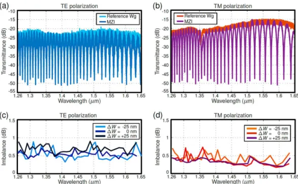
maintained, whereas waveguide width and gap size are altered in a factor of ∆W. Figure 3 shows the simulation results. An IL below 0.5 dB, an imbalance below 0.3 dB, and RL better than −40 dB in the 1200–1700 nm wave-length range are predicted for both the nominal and biased designs, conirming the resilience of the device against fabrication errors. It should be noted that at shorter wavelengths the strip-to-slot transition may start guiding higher order TE modes, resulting in slight power imbalance, below 0.1 dB for the nominal design. his efect is accentuated when increasing the waveguide width (∆W =+25 nm) and mitigated when reducing the waveguide width (∆W = −25 nm). Conversely, insertion losses decrease by increasing the waveguide width. herefore, our nominal design is a compromise between low insertion losses, lat imbalance and tolerances to fabrication errors. Figure 4 shows scanning electron microscope (SEM) images of the fabricated beam splitter before PMMA deposition (see the Methods section). he splitter was characterized using both a Mach-Zehnder interferometer (MZI) and cascaded stages using the experimental setup described in the Methods section. he MZI conigu-ration allows precise estimation of the imbalance, extracted from measured extinction ratio (ER)28,48. However,
insertion loss estimation from the MZI response is less accurate, as it inherently combines both MZI loss and chip-coupling loss. Given the low loss of our device, total insertion loss measured at the MZI is strongly afected by the non-uniformity of the chip-coupling loss, e.g. due to non-perfect cleaving of the facets. To overcome this limitation, insertion loss was accurately measured by characterizing the response of cascaded splitters32.
In the MZI coniguration, two identical splitters were connected in a back-to-back coniguration with an arm imbalance of 40 µm. Figure 5(a,b) show the measured transmittance spectra of the MZI interferometer, compris-ing two nominal splitters, for both the TE and TM polarizations compared to a reference strip waveguide. he device showed measured extinction ratios (ERs) higher than 20 dB and 25 dB over a 390 nm wavelength range (1.26–1.65 µm) for the TE and TM polarizations, respectively. he imbalance was calculated from the meas-ured ER28,48 for MZIs comprising nominal design and waveguide width variations of ±25 nm (see Fig. 5(c,d)).
Nominal and biased designs yield less than 0.9 dB in the full wavelength range for both polarizations, illustrating the robustness of the proposed approach.
Five beam splitter stages were cascaded to carry out an accurate measurement of the transmission spectrum of the device. We included both the nominal design and biased structures with waveguide width variations of ±25 nm, allowing us to determine the tolerance to fabrication errors. One output of each splitter stage was col-lected at the chip facet, whereas the second output was directed to the next splitter stage, enabling transmission measurement through the linear regression itting of the ive resulting signals. As shown in Fig. 6, the slot-based splitters exhibited a deviation of less than ±0.5 dB with respect to the ideal −3 dB transmission for both polari-zations within the 1260–1650 nm wavelength range. he same robust performance was demonstrated even when waveguide width variations of up to ±25 nm were introduced. Simulation analysis predicted deviations below Figure 2. (a) Efective index as a function of the wavelength for the fundamental and irst-order TE and TM slot waveguide modes. Slot waveguide with WR = 150 nm and GS = 100 nm (see Fig. 1). Higher order modes with efective index near ~1.45 are below the cut-of condition. Calculated insertion loss as a function of lengths LA (b) and LB (c), considered separately. (d) Insertion loss as a function of the overall strip-to-slot converter length (Fig. 1 section I) for the fundamental TE and TM modes. he lengths LA and LB are varied maintaining a 2:1 ratio. (e) Calculated insertion loss as a function of taper length LT in section III. he design wavelength of 1.55 µm is considered for insertion loss calculations in (b–e).
Figure 3. Insertion loss for TE (a) and TM (b) polarizations as a function of wavelength for the nominal design. Imbalance is also shown for TE (c) and TM (d) polarizations. Return loss calculated for TE (e) and TM (f) polarizations. We considered the nominal design (∆W = 0 nm) and deviations in all waveguide widths of ∆W = ±25 nm.
Figure 4. Scanning electron microscope images of the fabricated splitter. Insets (let to right): strip-to-slot mode converter (section I), central slot waveguide (section II) and slot-to-strip output taper (section III).
www.nature.com/scientificreports
www.nature.com/scientificreports/
Figure 5. Measured spectra of a Mach-Zehnder interferometer with back-to-back beam splitters, compared to a reference strip waveguide for TE (a) and TM (b) polarizations. All spectra are normalized to calibrate out setup loss. Imbalance extracted from measured ER in MZI with nominal and ±25 nm biased splitters for (c) TE and (d) TM polarizations.
Figure 6. Transmittance of splitters for (a) TE and (b) TM polarizations, measured through linear regression of the response of ive cascaded stages. Insertion loss for (c) TE and (d) TM polarizations obtained from transmittance of ive cascaded splitters and taking into account the worst-case imbalance from the MZI experiment. Measured optical relection signals in spatial domain of a nominal splitter for (e) TE and (f) TM polarizations, compared to those of a reference waveguide. he sample is 9 mm long, and the splitter is placed 2 mm away from the output facet.
0.25 dB. his small discrepancy is attributed to fabrication imperfections such as waveguide roughness. Insertion loss of the proposed beam splitter is obtained from the transmittance of the cascaded splitters and taking into account the worst-case imbalance from the MZI experiment. As shown in Fig. 6(c,d), our device yields insertion loss below 1 dB in a 390 nm bandwidth, for both polarizations, even in the presence of fabrication errors as large as ±25 nm. Finally, back-relections in the coupler are studied experimentally by transforming the output signal of the chip into the spatial domain through the minimum phase technique49. his process was performed for both
the splitter and a reference waveguide, showing no evidence of increased back-relections caused by the splitter for neither TE nor TM polarizations (Fig. 6(e,f)). Note that the peaks shown near 0 mm and 9 mm correspond to direct transmission and relection in the input facet, respectively, whereas any back-relection caused by the splitter would appear as a peak in the region near 7 mm. he absence of this latter peak is in good agreement with the low back-relection predicted by calculations.
Discussion
In conclusion, we have proposed and experimentally demonstrated an ultra-broadband and polarization-independent optical beam splitter based on a single-mode slot waveguide with a symmetric slot-to-strip transition. he single-mode operation of the slotted section prevents wavelength-dependent mode beating, which fundamentally limits the bandwidths of conventional DCs and MMIs, while the symmetric geom-etry ensures equal power splitting for both the TE and TM polarizations even with comparatively large fabrication errors. he splitter yields a near-ideal transmission of −3 ± 0.5 dB for both polarizations in an unprecedented wavelength bandwidth of 390 nm, covering the O, E, S, C and L telecommunication bands. his outstanding performance is maintained in the presence of fabrication deviations as large as ±25 nm, thereby relaxing fabri-cation constraints. We believe that the proposed optical beam splitter has excellent potential for use in the next generation of photonic integrated circuits as a key building block enabling dual-polarization and ultra-broadband silicon photonics devices.
Methods
Device fabrication and experimental characterization.
he beam splitter was fabricated in SOI wafers with a 220-nm-thick silicon and a 2 µm BOX layer. Electron beam lithography (Nanobeam NB-4 system, 80 kV) was used to deine the splitter pattern. A dry etching process with an inductively coupled plasma etcher (SF6 gas) was employed to transfer the pattern to the silicon layer. Finally, 1-µm-thick PMMA was deposited as the upper cladding layer.Devices were characterized using three tunable lasers, covering sequentially the 1260 nm to 1650 nm wavelength range. Light was injected into the chip via 3-µm-wide waveguide edge couplers, using a lensed polarization-maintaining fiber, after polarization selection with a rotating quarter-waveplate and a linear polarizer. Light coming out of the chip was directed through a microscope objective and a linear polarizer to a photodetector.
Data Availability
he data generated during and/or analysed during the current study are available from the corresponding author on reasonable request.
References
1. Reed, G. T., Mashanovich, G., Gardes, F. Y. & homson, D. J. Silicon optical modulators. Nat. Photonics 4, 518–526 (2010). 2. Zheng, X. et al. Ultra-eicient 10Gb/s hybrid integrated silicon photonics transmitter and receiver. Opt. Express 19, 5172–5186
(2011).
3. Dong, P. et al. Monolithic silicon photonic integrated circuits for compact 100 + Gb/s coherent optical receivers and transmitters. IEEE J. Sel. Top. Quantum Electron. 20, 1–8 (2014).
4. Vacondio, F. et al. A silicon modulator enabling RF over iber for 802.11 OFDM signals. IEEE J. Sel. Top. Quantum Electron. 16, 141–148 (2010).
5. Chow, C. W., Yeh, C. H., Lo, S. M., Li, C. & Tsang, H. K. Long-reach radio-over-iber signal distribution using single-sideband signal generated by a silicon-modulator. Opt. Express 19, 11312–11317 (2011).
6. De Vos, K., Bartolozzi, I., Schacht, E., Bienstman, P. & Baets, R. Silicon-on-insulator microring resonator for sensitive and label-free biosensing. Opt. Express 15, 7610–7615 (2007).
7. Estevez, M. C., Alvarez, M. & Lechuga, L. M. Integrated optical devices for lab-on-a-chip biosensing applications. Laser Photonics Rev. 6, 463–487 (2012).
8. Poulton, C. V. et al. Coherent solid-state LIDAR with silicon photonic optical phased arrays. Opt. Lett. 42, 4091–4094 (2017). 9. Redding, B., Liew, S. F., Sarma, R. & Cao, H. Compact spectrometer based on a disordered photonic chip. Nat. Photonics 7, 746–751
(2013).
10. Velasco, A. V. et al. High-resolution Fourier-transform spectrometer chip with microphotonic silicon spiral waveguides. Opt. Lett.
38, 706–708 (2013).
11. Koos, C. et al. All-optical high-speed signal processing with silicon-organic hybrid slot waveguides. Nat. Photonics 3, 216–219 (2009).
12. Jacobsen, R. S. et al. Strained silicon as a new electro-optic material. Nature 441, 199–202 (2006).
13. Chen, X., Liu, W., Zhang, Y. & Shi, Y. Polarization-insensitive broadband 2x2 3 dB power splitter based on silicon-bent directional couplers. Opt. Lett. 42, 3738–3740 (2017).
14. Ofrein, B. J., Bona, G. L., Germann, R., Massarek, I. & Erni, D. A very short planar silica spot-size converter using nonperiodic segmented waveguide. J. Light. Technol. 16, 1680–1685 (1998).
15. Cheben, P., Xu, D. X., Janz, S. & Densmore, A. Subwavelength waveguide grating for mode conversion and light coupling in integrated optics. Opt. Express 14, 4695–4702 (2006).
16. Cheben, P. et al. Refractive index engineering with subwavelength gratings for efficient microphotonic couplers and planar waveguide multiplexers. Opt. Lett. 35, 2526–2528 (2010).
17. Marcatili, E. A. J. Dielectric rectangular waveguide and directional coupler for integrated optics. Bell Syst. Tech. J. 48, 2071–2102 (1969).
www.nature.com/scientificreports
www.nature.com/scientificreports/
18. Trinh, P. D., Yegnanarayanan, S. & Jalali, B. Integrated optical directional couplers in silicon-on-insulator. Electron. Lett. 31, 2097–2098 (1995).
19. Yamada, H., Chu, T., Ishida, S. & Arakawa, Y. Optical directional coupler based on Si-wire waveguides. IEEE Photonics Technol. Lett.
17, 585–587 (2005).
20. Xing, J. et al. Silicon-on-insulator-based adiabatic splitter with simultaneous tapering of velocity and coupling. Opt. Lett. 38, 2221–2223 (2013).
21. Cong, G. W. et al. Demonstration of a 3-dB directional coupler with enhanced robustness to gap variations for silicon wire waveguides. Opt. Express 22, 2051–2059 (2014).
22. Yun, H. et al. 2x2 broadband adiabatic 3-dB couplers on SOI strip waveguides for TE and TM modes. In CLEO: Sci. Innov. Sh1F–8 (2015).
23. Xu, L. et al. Polarization independent adiabatic 3-dB coupler for silicon-on-insulator. In CLEO: Sci. Innov. SF1I–5 (2017). 24. Tamazin, H. et al. Ultra-broadband compact adiabatic coupler in silicon-on-insulator for joint operation in the C- and O-bands. In
CLEO: Sci. Innov. Sh4B–4 (2018).
25. Yun, H., Chrostowski, L. & Jaeger, N. A. Ultra-broadband 2x2 adiabatic 3 dB coupler using subwavelength-grating-assisted silicon-on-insulator strip waveguides. Opt. Lett. 43, 1935–1938 (2018).
26. Yun, H. et al. Broadband 2x2 adiabatic 3 dB coupler using silicon-on-insulator sub-wavelength grating waveguides. Opt. Lett. 41, 3041–3044 (2016).
27. Halir, R. et al. Colorless directional coupler with dispersion engineered sub-wavelength structure. Opt. Express 20, 13470–13477 (2012).
28. Wang, Y. et al. Compact broadband directional couplers using subwavelength gratings. IEEE Photonics J. 8, 1–8 (2016). 29. Yajima, H. Dielectric thin-ilm optical branching waveguide. Appl. Phys. Lett. 22, 647–649 (1973).
30. Burns, W. & Milton, A. Mode conversion in planar-dielectric separating waveguides. IEEE J. Quantum Electron. 11, 32–39 (1975). 31. Rickman, A. G. & Reed, G. T. Silicon-on-insulator optical rib waveguides: loss, mode characteristics, bends and y-junctions. IEE
P-Optoelectron. 141, 391–393 (1994).
32. Zhang, Y. et al. A compact and low loss Y-junction for submicron silicon waveguide. Opt. Express 21, 1310–1316 (2013).
33. Sakai, A., Fukazawa, T. & Baba, T. Low loss ultra-small branches in a silicon photonic wire waveguide. IEICE Trans. Electron. 85, 1033–1038 (2002).
34. Wang, Y., Gao, S., Wang, K. & Skaidas, E. Ultra-broadband and low-loss 3 dB optical power splitter based on adiabatic tapered silicon waveguides. Opt. Lett. 41, 2053–2056 (2016).
35. Soldano, L. B. & Pennings, E. C. Optical multi-mode interference devices based on self-imaging: principles and applications. J. Light. Technol. 13, 615–627 (1995).
36. Maese-Novo, A. et al. Wavelength independent multimode interference coupler. Opt. Express 21, 7033–7040 (2013).
37. Halir, R. et al. Ultra-broadband nanophotonic beamsplitter using an anisotropic sub-wavelength metamaterial. Laser Photonics Rev.
10, 1039–1046 (2016).
38. Li, X. et al. Compact and low-loss silicon power splitter based on inverse tapers. Opt. Lett. 38, 4220–4223 (2013).
39. Rasigade, G., Le Roux, X., Marris-Morini, D., Cassan, E. & Vivien, L. Compact wavelength-insensitive fabrication-tolerant silicon-on-insulator beam splitter. Opt. Lett. 35, 3700–3702 (2010).
40. Han, L., Kuo, B. P. P., Alic, N. & Radic, S. Ultra-broadband multimode 3 dB optical power splitter using an adiabatic coupler and a Y-branch. Opt. Express 26, 14800–14809 (2018).
41. Frandsen, L. H. et al. Ultralow-loss 3-dB photonic crystal waveguide splitter. Opt. Lett. 29, 1623–1625 (2004).
42. Feng, N. N., Sun, R., Kimerling, L. C. & Michel, J. Lossless strip-to-slot waveguide transformer. Opt. Lett. 32, 1250–1252 (2007). 43. Palmer, R. et al. Low-loss silicon strip-to-slot mode converters. IEEE Photonics J. 5, 2200409–2200409 (2013).
44. Xu, Q., Almeida, V. R., Panepucci, R. R. & Lipson, M. Experimental demonstration of guiding and conining light in nanometer-size low-refractive-index material. Opt. Lett. 29, 1626–1628 (2004).
45. Almeida, V. R., Xu, Q., Barrios, C. A. & Lipson, M. Guiding and conining light in void nanostructure. Opt. Lett. 29, 1209–1211 (2004).
46. Palik, E. D. Handbook of optical constants of solids (Academic press, 1998). 47. MODE Solutions, Lumerical Solutions Inc. http://www.lumerical.com/.
48. Bogaerts, W. et al. Silicon microring resonators. Laser Photonics Rev. 6, 47–73 (2012).
49. Halir, R. et al. Characterization of integrated photonic devices with minimum phase technique. Opt. Express 17, 8349–8361 (2009).
Acknowledgements
his work has been funded in part by the Spanish Ministry of Science, Innovation and Universities under grants TEC2015-71127-C2-1-R (FPI scholarship BES-2016-077798) and IJCI-2016-30484; and the Community of Madrid (S2013/MIT-2790). his project has received funding from the EMPIR program (JRP-i22 14IND13 Photind), co-inanced by the participating countries and the European Union’s Horizon 2020 research and innovation program; and from the Horizon 2020 research and innovation program under the Marie Sklodowska-Curie Grant No. 734331. This work has been partially funded by the Agence National pour la Recherche, Project MIRSPEC (ANR-17-CE09-0041) and the H2020 European Research Council (ERC) (ERC POPSTAR 647342). The sample fabrication has been performed at the Plateforme de Micro-Nano-Technologie/C2N, which is partially funded by the “Conseil Général de l’Éssonne”. his work was partly supported by the French RENATECH network.
Author Contributions
C.A.R. and D.G.-A. proposed the concept. D.G.-A. and C.A.R. designed the devices. X.L.R. and E.D.V. fabricated the samples. D.G.-A., C.L., E.D.V., M.B. and L.V. performed the experimental characterization. D.G.-A., E.C., D.M.-M., A.V.V., P.C., L.V. and C.A.R. discussed the results and wrote the manuscript.
Additional Information
Competing Interests: he authors declare no competing interests.
Publisher’s note: Springer Nature remains neutral with regard to jurisdictional claims in published maps and institutional ailiations.
Open Access This article is licensed under a Creative Commons Attribution 4.0 International License, which permits use, sharing, adaptation, distribution and reproduction in any medium or format, as long as you give appropriate credit to the original author(s) and the source, provide a link to the Cre-ative Commons license, and indicate if changes were made. he images or other third party material in this article are included in the article’s Creative Commons license, unless indicated otherwise in a credit line to the material. If material is not included in the article’s Creative Commons license and your intended use is not per-mitted by statutory regulation or exceeds the perper-mitted use, you will need to obtain permission directly from the copyright holder. To view a copy of this license, visit http://creativecommons.org/licenses/by/4.0/.