Publisher’s version / Version de l'éditeur:
Vous avez des questions? Nous pouvons vous aider. Pour communiquer directement avec un auteur, consultez la première page de la revue dans laquelle son article a été publié afin de trouver ses coordonnées. Si vous n’arrivez pas à les repérer, communiquez avec nous à PublicationsArchive-ArchivesPublications@nrc-cnrc.gc.ca.
Questions? Contact the NRC Publications Archive team at
PublicationsArchive-ArchivesPublications@nrc-cnrc.gc.ca. If you wish to email the authors directly, please see the first page of the publication for their contact information.
https://publications-cnrc.canada.ca/fra/droits
L’accès à ce site Web et l’utilisation de son contenu sont assujettis aux conditions présentées dans le site LISEZ CES CONDITIONS ATTENTIVEMENT AVANT D’UTILISER CE SITE WEB.
Third International Workshop: Structures in Fire [Proceedings], pp. 1-15, 2004-05-01
READ THESE TERMS AND CONDITIONS CAREFULLY BEFORE USING THIS WEBSITE.
https://nrc-publications.canada.ca/eng/copyright
NRC Publications Archive Record / Notice des Archives des publications du CNRC :
https://nrc-publications.canada.ca/eng/view/object/?id=75af6a1f-5e97-43fe-9346-e36530dcc3e1 https://publications-cnrc.canada.ca/fra/voir/objet/?id=75af6a1f-5e97-43fe-9346-e36530dcc3e1
Archives des publications du CNRC
This publication could be one of several versions: author’s original, accepted manuscript or the publisher’s version. / La version de cette publication peut être l’une des suivantes : la version prépublication de l’auteur, la version acceptée du manuscrit ou la version de l’éditeur.
Access and use of this website and the material on it are subject to the Terms and Conditions set forth at
Modelling the fire behaviour of FRP-strengthened reinforced concrete columns
Modelling the fire behaviour of FRP-strengthened reinforced concrete columns
Bisby, L.; Kodur, V.; Green, M.
NRCC-47027
A version of this document is published in / Une version de ce document se trouve dans : Structures in Fire, Proceedings of the 3rd International Workshop,
Ottawa, Ontario, May 10-11, 2004, pp. 1-15
MODELLING THE FIRE BEHAVIOUR OF
FRP-STRENGTHENED REINFORCED CONCRETE COLUMNS
Luke BISBY
Dept. Of Civil Eng., Queen’s Univ., Kingston, ON, Canada bisby@civil.queensu.ca
Venkatesh KODUR
Fire Risk Management, Bldg. M-59, National Research Council, Ottawa, ON, Canada venkatesh.kodur@nrc-cnrc.gc.ca
Mark GREEN
Dept. Of Civil Eng., Queen’s Univ., Kingston, ON, Canada greenm@civil.queensu.ca
ABSTRACT
Rehabilitation and strengthening of reinforced concrete (RC) structures have changed significantly in recent years, due in large part to the introduction of fibre-reinforced polymers (FRP) as economical and effective infrastructure materials. FRPs are currently gaining acceptance in a wide range of civil engineering applications, including the external flexural repair of RC beams and slabs, and axial strengthening and ductility enhancement of RC columns, both of which can be achieved by bonding FRP plates and sheets to the exterior of the members. To date, the use of FRP materials for repair of RC structures has been limited primarily to bridge and transportation structures, while relatively few large scale applications have been conducted in buildings.
One major factor preventing the widespread use of FRP materials in buildings, where fire resistance criteria must satisfied, is the lack of information available on the fire performance of FRP materials in general, and on the overall behaviour of FRP-strengthened concrete members during fire. Since FRP materials are sensitive to the effects of elevated temperatures, there are a number of significant concerns that must be considered with respect to the fire performance of
FRP-strengthened members. These concerns include strength and stiffness degradation at high temperature, and loss of bond. To address these concerns, an ongoing collaborative research project is being conducted by researchers at Queen’s University, Canada, and the National Research Council of Canada in conjunction with various industrial partners, to study the effects of fire on concrete slabs, beams, and columns strengthened with externally-bonded FRP materials.
This paper presents details and results of a numerical model developed to simulate both the heat transfer behaviour and load-carrying capacity of FRP-wrapped and insulated RC columns in fire. The model that has been developed is unique in that it accounts for the variation in thermal and mechanical properties of the columns’ constituent materials with temperature, including FRP. In addition, the model accounts for the confining effect of a circumferential FRP wrap on the stress-strain characteristics of the concrete. The model’s predictions are compared against results from full-scale fire tests and are shown to agree satisfactorily.
KEYWORDS: fire resistance, fibre reinforced polymers, columns, reinforced concrete,
strengthening, numerical modelling.
INTRODUCTION
Fibre reinforced polymers (FRPs) have, in the last fifteen years or so, become increasingly popular as materials for externally-bonded repair systems for deteriorated or under-strength reinforced concrete (RC) members. One application for which FRPs have shown significant promise, and have indeed been used in hundreds of field applications around the world, is as external confining reinforcement for RC columns [1]. In this application, unidirectional FRP materials consisting of either glass or carbon fibres and an epoxy polymer adhesive/matrix are bonded, generally in the circumferential direction, to the surface of an existing concrete member. Research has shown that FRP wraps are effective at increasing both the strength and ductility of RC columns. The mechanisms of FRP confinement and the various factors influencing design of FRP-wrapped concrete members are now relatively well-understood [1], and design guidelines are currently available for their use in many countries [2, 3, 4, 5].
However, with new and innovative structural systems come a host of associated factors that require investigation. For FRP, one primary concern is that exposure to high temperatures, as would be expected during a building fire, could lead to failure of the FRP repair system and premature collapse of the strengthened member. Indeed, recently published research gap analyses on the use of FRP in structural applications have identified fire performance as a critical factor requiring study before FRP can be used with confidence in strengthening applications in buildings [6, 7].
To address concerns associated with the fire performance of FRP repair systems for concrete, a comprehensive collaborative research program is currently underway at the National Research Council of Canada in conjunction with Queen’s University, the Networks of Centres of Excellence on Intelligent Sensing for Innovative Structures (ISIS Canada), and industry partners Fyfe Co., San Diego, CA and Watson Bowman Acme Corp., Cleveland, OH. As part of this study, full-scale fire tests have been conducted on loaded FRP-wrapped and insulated circular
RC columns, and numerical models have been developed to simulate their behaviour in fire. This paper presents details of the numerical models that have been developed to date, and verifies these models against test data obtained during the current research program as well as data available in the literature.
BACKGROUND
It is now well recognized that both the strength and ductility of concrete compressive members can be greatly enhanced using transverse FRP wraps [1]. The observed increases in strength and ductility can be attributed to the fact that the FRP wrap generates a confining pressure on the dilating concrete core when the column is subjected to compressive load. This places the concrete in a state of triaxial stress and increases both the ultimate strength and strain of the concrete by reducing shear stresses and controlling crack initiation. It is evident that these increases in strength and ductility depend primarily on the mechanical properties of the FRP wrap, which may be severely degraded at a high temperature. Figure 1 shows typical axial compressive stress-strain behaviour for circular concrete columns incorporating steel-reinforcing spirals or FRP wraps.
The mechanical and bond properties of FRP materials deteriorate rapidly above their polymer matrices’ glass transition temperature (Tg). Thus,
the structural performance of FRP-wrapped columns during fire needs to be studied before these strengthening systems can be used with confidence in buildings. Few studies investigating the fire performance of FRP-strengthened concrete members exist in the literature. A series of full-scale fire tests have been conducted in Europe to investigate the fire performance of flexurally FRP-strengthened and insulated concrete beams and slabs [9] and have demonstrated the sensitivity of FRP strengthening systems to temperatures greater than their matrix Tg. However, no research has yet
been reported studying performance of FRP-wrapped concrete columns at a high temperature. Normalized Axial Strain (εc/ε'co)
0 5 10 15 20 Normalize d Axia l Stress ( f'c /f'cc ) 0.0 0.5 1.0 1.5 2.0 2.5 Plain Concrete Steel Spiral GFRP-Wrapped CFRP-Wrapped
FIGURE 1 : Typical effects of FRP confinement on circular reinforced concrete columns [8].
FIRE ENDURANCE
The fire endurance of RC columns has traditionally been defined in terms of their load-carrying capacity during exposure to a standard fire. In North America, the standard fire is defined by ASTM E119 [10] or CAN/ULC S101 [11]. Columns are required to carry their full unfactored service load for the required fire duration, which is generally between two and five hours,
depending on the type of building and its use and occupancy. Thus, the fire endurance of FRP-wrapped columns is considered herein to be defined in terms of the columns’ ability to carry their service load during fire, regardless of whether the FRP has exceeded its matrix Tg. It is
important to note that there are a number of environmental fire hazards associated with combustion of FRP materials that must be considered when these materials are considered for use in buildings, although these are not discussed in detail here.
MODELS
Full-scale fire tests are relatively time consuming and costly to perform, and while the current study includes fire tests on insulated FRP-wrapped RC columns, it was desired to develop numerical models that could be verified based on the test results and subsequently used to conduct parametric studies to investigate the effects of a number of column parameters on member behaviour in fire. Once validated, the models can also be used to provide design guidance to engineers wishing to implement FRP strengthening applications in buildings. The numerical models that have been developed are similar in methodology to those developed previously by researchers at the National Research Council of Canada [12]. They consist of a coupled heat transfer/strain equilibrium analysis which can approximate both the axial crushing and/or buckling strength of unwrapped, FRP-wrapped, and insulated FRP-wrapped circular concrete columns during exposure to the standard fire. The models are unique in that they have been extended to include the effects of both the FRP wraps and supplemental insulation on heat transfer, and in that they account for the effects of the variable confining pressure applied by an FRP wrap on the crushing or buckling strength of a concrete column during fire.
Heat transfer model
The heat transfer model has been developed using a finite difference methodology in which the column is divided into a series of ring elements, as shown schematically in Figure 2. For each ring element an energy balance is formulated, leading to a series of equations that describe a relatively straightforward one-dimensional explicit finite difference analysis. The boundary condition at the surface of the column is treated by assuming that heat transfer is due to radiation only, an assumption which has been used successfully in the past [12]. The equations have been derived in a similar fashion as has been presented previously [12] and the details are omitted here.
The effect of moisture in the concrete on the heat transfer within the member is accounted for by assuming that evaporation begins in a ring element when its temperature reaches 100˚C, and that all heat subsequently supplied to the element is used for dehydration until all of the moisture has evaporated. Thus the temperature in an element remains constant at 100˚C until all the water has evaporated. The analysis does not currently account for movement of moisture within the pore structure of the cement paste, nor does it consider the potential for thermally-induced pore pressure build-up or spalling. The member is assumed to be infinitely long, and the effects of
reinforcing steel on the heat transfer within the member are assumed to be negligible. The analysis accounts for the variation in thermal properties of all materials involved with temperature, using relationships discussed in detail below.
Column Centreline Insulation Fire Wrap Concrete Line of Symmetry Rc Rw
FIGURE 2 : Idealized discretization of insulated FRP-wrapped column for heat-transfer analysis.
The column is assumed initially to be at room temperature. The heat transfer equations are then used to step forward through time and to determine the spatial and temporal temperature distribution in the column, at any location, based on the thermal properties and temperatures of the adjacent elements at the previous time step. In this manner, the complete temperature history throughout the column can be obtained.
Load capacity model
The load capacity of an FRP-wrapped column during exposure to fire depends on the stress-strain behaviour of the concrete in the cross-section, which in turn depends on the temperature of the concrete at that particular location and time and on the lateral confining pressure applied by the FRP wrap. However, the confinement pressure depends also on the temperature of the wrap (temperature strongly influences the wrap’s mechanical properties) and on the lateral dilation of the concrete. Thus, an iterative analysis is required.
The load capacity of the column during fire is calculated both for the axial crushing strength and the buckling strength. The buckling strength, which generally governs for members that are likely to be encountered in practice, is calculated using a procedure similar to that suggested by
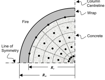
Lie and Celikkol [12] for conventionally-reinforced concrete columns, wherein the column cross-section is divided into a series of annular elements, as shown in Figure 3. Neither the FRP wrap nor the insulation is assumed to provide any direct contribution to the axial strength of the column. However, the effect of the confinement provided by the FRP is included in the analysis using an iterative confinement model.
Column Centreline Wrap Fire Line of Symmetry Concrete Rc Rw
FIGURE 3 : Idealized discretization of an insulated FRP-wrapped column for buckling strength analysis.
For each element in the column’s cross-section, the temperature, stress, and strain are assumed to be represented by those at the centroid of the element. The axial strain that causes stress in any element is equal to the sum of the free thermal strain, the bending strain, and the column’s average axial strain, since all elements are subjected to both axial and flexural loads (in the buckling analysis). Once the strain in each element is determined, its stress-strain characteristics at its current temperature, determined using an iterative Spolestra and Monti [8] confinement routine in combination with concrete thermomechanical subroutines suggested by Lie [13] for unconfined concrete, can be used to determine the element’s stress. In this manner the elemental force due to each element or reinforcing bar under some axial compressive load can be obtained. The curvature of the column is assumed to vary linearly from the inflection points to mid-height, as shown in Fig. 4, so for any assumed curvature the mid-height deflection of the column can be calculated (refer to Fig. 4). At each instant in time, the overall axial strain in the column is varied until the internal moment at mid-height is equal to the external moment due to the product of applied load and mid-height lateral deflection.
To facilitate the numerical analysis, an initial eccentricity of the axial load must be assumed. In the current study, this eccentricity has been assumed as eo = 15 + 0.03d (mm), where d is the
column diameter, in accordance with the minimum eccentricity recommended by ACI 318 [14] for conventional RC columns.
By repeating the above procedure for increasing curvatures, load-deflection plots can be obtained for a range of times during exposure to fire. From these plots, the maximum load capacity of the column can determined, and a plot of load capacity versus fire exposure time can be developed (Fig. 9, for example). The above model can also be used to predict the axial deformation of circular FRP-wrapped RC columns during fire, as well as their pure axial (crushing) strength. A flowchart showing the overall program logic is shown in Figure 5, and a complete discussion of the load capacity analysis is given by Bisby [15].
FRP Confinement Model
A unique aspect of the numerical model described herein is that it accounts for the effects of FRP confinement on the strength of FRP-wrapped RC columns exposed to fire. The confinement effect is incorporated into the analysis using a modified version of an iterative confinement procedure developed by Spolestra and Monti [8].
( )
12 2 KL y=χ P Pe
oKL
y
χ
During fire, the mechanical properties of the concrete in the column and the FRP wrap, both required as inputs for the Spolestra and Monti confinement routine, are reduced. In addition, the concrete’s properties are non-uniform over the column cross-section due to thermal gradients. Thus, an extension of the confinement model was developed to account for the damaging effects of fire on the properties of both the concrete and the FRP.
P
Deflection Curvature
FIGURE 4 : Assumed variation in curvature for buckling analysis.
With the overall axial strain in the concrete assumed, and the temperatures throughout the cross-section known, the maximum unconfined concrete stress and strain for each ring of the column, and the modulus and ultimate tensile strength of the wrap (based on its average temperature) are obtained from thermomechanical subroutines. These mechanical properties are used as inputs for the Spolestra and Monti model, and the overall confining pressure is determined. Once the confining pressure is known, it can be used to modify the stress-strain characteristics of the concrete in each ring of the column, also using the Spolestra and Monti confinement routine, as required for the buckling analysis discussed previously.
The confinement model, as implemented in the current analysis, assumes a constant confining pressure at all points over the column’s cross-section. Tests have indicated that, for columns subjected to both axial and flexural loads, a bonded FRP wrap actually provides a higher level of confinement in the compressive flexural regions of the column. The assumption of a constant confining pressure is thus conservative.
Start
Calculation of Fire Temperature (ASTM E119 / ULC S101)
Calculation of Member Temperatures (Finite Difference) Thermal Properties of Constituents Equilibrium Conditions @ Midspan?
Initialize Time Step
Initial Curvature Assumed
Initial Axial Strain Assumed
Calculate Confining Pressure (Monti & Spolestra Routine)
Calculate Elemental Force Components (Equilibrium Analsysis) Maximum Load Capacity Reached? Fire Duration Exceeded (analysis Complete?) YES YES Increment Axial Strain Increment Curvature Increment Time NO NO NO Stress-Strain Properties of Constituents Stress-Strain Properties of Constituents YES End
FIGURE 5 : Flowchart showing the overall program logic for buckling strength analysis.
MATERIAL PROPERTIES AT ELEVATED TEMPERATURE
For the above models to provide accurate predictions of the heat transfer within, and the load capacity of insulated FRP-wrapped concrete columns, a detailed knowledge of the variation in both the thermal and mechanical properties of the constituent materials with temperature is required. For concrete and steel, thermal and mechanical behaviour at a high temperature have been studied extensively in the literature. For the purposes of the current analyses, the variation in thermal and mechanical properties of steel and concrete with temperature has been assumed based on mathematical relationships suggested by Lie [13].
In contrast to steel and concrete, the thermal and mechanical properties of FRP materials at a high temperature have not been extensively studied, particularly for FRPs used in infrastructure applications. In the current analysis, the thermal properties of FRPs have been assumed to vary as suggested by previous researchers [16], who performed tests on a specific carbon/epoxy FRP that has been used in aerospace applications. The resulting assumed variation in thermal properties of FRP is shown in Figure 6.
The variation in mechanical properties of FRPs with increasing temperature is also poorly understood, and, because of the enormous variety of FRP materials currently available in industry, it is difficult to arrive at generalizations with respect to their high temperature behaviour. For the purposes of the current analysis, a series of semi-empirical analytical relationships were derived based on least-squares regression analysis of high temperature tensile strength data reported in the literature. These data were obtained from tests conducted on a variety of carbon and glass FRP materials, and in many cases the specific composition and properties of the FRPs remains unknown. The analytical relationships assume that the behaviour can be described by sigmoid functions, as suggested by previous authors [17]. The resulting assumed variation in strength and stiffness of carbon and glass FRP materials are given in Figure 7, where significant scatter is evident in the data. Tensile tests at high temperature on the specific FRP materials used in the current study will be required to more confidently validate the numerical models. In addition, the current analysis makes no attempt to specifically account for deterioration of the FRP-concrete bond at high temperature, which is likely severe at temperatures above Tg.
Temperature (oC) 0 200 400 600 800 1000 0 1 2 3 4 5 6 Specific Heat (kJ/kg.K) Density (g/cm3) Thermal Conductivity (W/m.K)
FIGURE 6 : Assumed variation in thermal properties of FRP with temperature [16]. (a) Temperature (oC) 0 200 400 600 800 % Streng th Remain ing 0 20 40 60 80 100 120 CFRP Exp. CFRP Model GFRP Exp. GFRP Model (b) Temperature (oC) 0 200 400 600 800 % Modulus Re maining 0 20 40 60 80 100 120 CFRP Exp. CFRP Model GFRP Exp. GFRP Model
FIGURE 7 : Assumed variation in (a) strength and (b) stiffness of FRP with temperature (based on semi-empirical regression analysis performed by Bisby [15]).
No. Source Diam. (mm) Principal steel reinf. f’c (MPa) fy (MPa) FRP wrap1 Fire insulation2 1 Lie & Celikkol, 1992 356 6 Ø 20mm 42 414 -- -- 2 Lie & Celikkol, 1992 356 6 Ø 20mm 42 414 -- -- 3 Franssen & Dotreppe, 2003 300 6 Ø 12mm 60 500 -- -- 4 Franssen & Dotreppe, 2003 300 6 Ø 12mm 60 500 -- -- 5 Franssen & Dotreppe, 2003 300 6 Ø 20mm 60 500 -- -- 6 Franssen & Dotreppe, 2003 300 6 Ø 20mm 60 500 -- -- 7 Bisby, 2003 400 8 Ø 20mm 39 456 1-layer 32 mm 8 Bisby, 2003 400 8 Ø 20mm 40 456 1-layer 57 mm
1
Proprietary Tyfo® SCH system carbon/epoxy FRP produced by Fyfe Co. LLC, San Diego, CA
2
Proprietary Tyfo® EI/VG insulation produced by Fyfe Co. LLC, San Diego, CA.
Table 1 : selected details of columns used to verify the numerical models.
MODEL VERIFICATION
The models described above have been verified against data available in the literature [12, 18] and against data obtained from full-scale tests conducted by the authors [15]. Table 1 shows selected details of eight fire-tested concrete columns that have been used to verify the models. Tests available in the literature (columns 1 through 6 in Table 1) consisted of full-scale fire tests on conventionally-reinforced concrete columns without insulation or FRP wraps. The authors have recently conducted two full-scale fire tests on insulated FRP-wrapped concrete columns (columns 7 and 8 in Table 1), the complete details of which will be published elsewhere.
Temperatures
Figure 8a shows experimental and predicted temperatures in the concrete at various depths as a function of fire exposure time for columns 1 and 2 of Table 1. At a depth of 25 mm there is generally good agreement between the experimental and predicted temperatures, although the model tends to under-predict temperatures within the first hour of fire exposure. At depths of 64 and 178 mm the experimental curves are characterized by rapid increases in temperature followed by regions of relatively constant temperature. This behaviour is more pronounced at greater depths and has been attributed by previous authors [12, 13] to thermally-induced moisture migration in the concrete which is not accounted for in the model. Hence, the numerical model tends to under-predict concrete temperatures early in the fire exposure, with closer agreement demonstrated later in the exposure. The reader will recognize that the late-stage temperatures are those that play an important role in determining the fire endurance of the columns, and hence the initial discrepancy is not of major concern.
Figure 8b shows experimental and predicted temperatures in the concrete at various depths as a function of fire exposure time for column 8 of Table 1; a carbon FRP-wrapped RC column with 57 mm of the Tyfo® EI/VG sprayed cementitious insulation system applied to the exterior of
the wrap. Again, the model predictions agree reasonably well with the experimental data, and the model accurately captures the overall trends observed in the test data. However, the model does not precisely capture the 100˚C temperature plateau observed in the test data at the level of the FRP wrap. This can be explained by considering that the model does not explicitly account for the evaporation of moisture from the insulation at 100˚C, nor does it account for moisture movement within the insulation. The model accounts for moisture evaporation in the insulation by artificially increasing the specific heat of the insulation elements at temperatures near 100˚C. While capturing the 100˚C plateau is not critical for calculating the structural fire endurance of the FRP-wrapped columns, it could become important if fire endurance is defined in terms of the matrix Tg, since Tg is close to 100˚C for many currently available FRPs. Further work is
thus required to allow more accurate modelling of heat transfer within the insulation and to obtain more accurate predictions at temperatures near 100˚C.
(a) Exposure Time (min)
0 60 120 180 240 300 T e mperat u re ( o C) 0 200 400 600 800 1000 1200 64 mm Depth 178 mm Depth 25 mm Depth Experimental Data Model Predictions ASTM E119 (b) Time (min) 0 60 120 180 240 300 T e mperat ure ( o C) 0 200 400 600 800 1000 1200 Fire-Insulation Interface Insulation-FRP Interface FRP-Concrete Interface Fire (ASTM E119) Experimental Data Model Predictions
FIGURE 8 : Predicted and observed temperatures at various locations during fire tests by (a) Lie and Celikkol [12] and (b) Bisby [15].
Time (min)
0 60 120 180 240 300 360
Buckling Load Capa
c it y (kN) 0 2000 4000 6000 8000 Unwrapped Wrapped No. 8 No. 7 Test Data Service Load Load capacity
Figure 9 shows the predicted buckling strength of columns 7 and 8 (insulated FRP-wrapped columns) as a function of fire exposure. Also included in Figure 9 are predicted fire endurance curves for equivalent columns in the unwrapped and wrapped but uninsulated conditions. Fire endurances (failure loads) observed during fire testing of columns 7 and 8 have been included as points in Figure 9.
FIGURE 9 : Predicted and observed concentric axial load capacity during fire tests performed by Bisby [15].
Good agreement is evident between the model predictions and experimentally observed fire endurances for the insulated FRP-wrapped
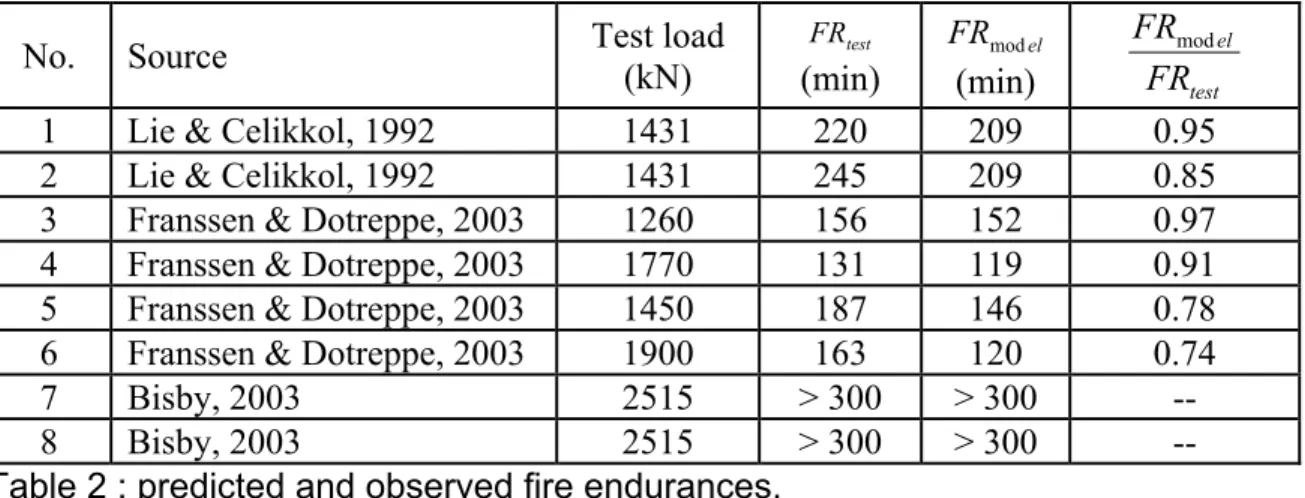
columns. However, with only two data points it is not possible to conclusively verify the model’s predictions. More tests are planned during 2004 to provide additional validation data. However, credence is given to the model’s predictive abilities by comparing the predictions of the model with fire test data available for conventional RC columns. Table 2 gives a comparison of predicted and observed fire endurances for all eight of the columns listed in Table 1. It is evident that the model satisfactorily predicts the fire endurance of circular RC columns, and that it appears slightly conservative (from 3% to 16%).
No. Source Test load
(kN) test FR (min) el FRmod (min) test el FR FRmod
1 Lie & Celikkol, 1992 1431 220 209 0.95 2 Lie & Celikkol, 1992 1431 245 209 0.85 3 Franssen & Dotreppe, 2003 1260 156 152 0.97 4 Franssen & Dotreppe, 2003 1770 131 119 0.91 5 Franssen & Dotreppe, 2003 1450 187 146 0.78 6 Franssen & Dotreppe, 2003 1900 163 120 0.74 7 Bisby, 2003 2515 > 300 > 300 -- 8 Bisby, 2003 2515 > 300 > 300 -- Table 2 : predicted and observed fire endurances.
FRP-WRAPPED COLUMNS IN FIRE: MODEL PREDICTIONS
Referring to Figure 9, the predicted initial (room temperature) strength of the unwrapped RC column is slightly less than that predicted for the FRP-wrapped columns due to the confining effect of the wrap. It is interesting to note that the predicted initial strength increase due to FRP wrapping is relatively small (only about 4%). This can be explained by considering that Figure 9 presents the predicted buckling strength of the columns, and FRP confinement cannot be
expected to significantly increase the elastic modulus of the concrete. Hence, the room temperature buckling strength of the columns is increased only slightly by FRP wrapping. Figure 9 also suggests that an RC column with insulation but without FRP would presumably perform similarly to an FRP-wrapped and insulated column during fire, since the structural
effectiveness of the FRP is predicted to be lost during fire exposure, even for well-insulated columns, and because FRP wrapping does not significantly increase the columns’ buckling strength. However, it is important to recognize that columns are not wrapped with FRP for increased fire endurance, but rather for greater axial load capacity or for seismic upgrade. In these cases, the analysis presented herein suggests that fire protection is required to ensure that the overall structural member has sufficient capacity to carry the increased expected service load
at the elevated temperatures experienced during fire. The insulation is not required specifically to protect the FRP wrap.
Axial Deformation
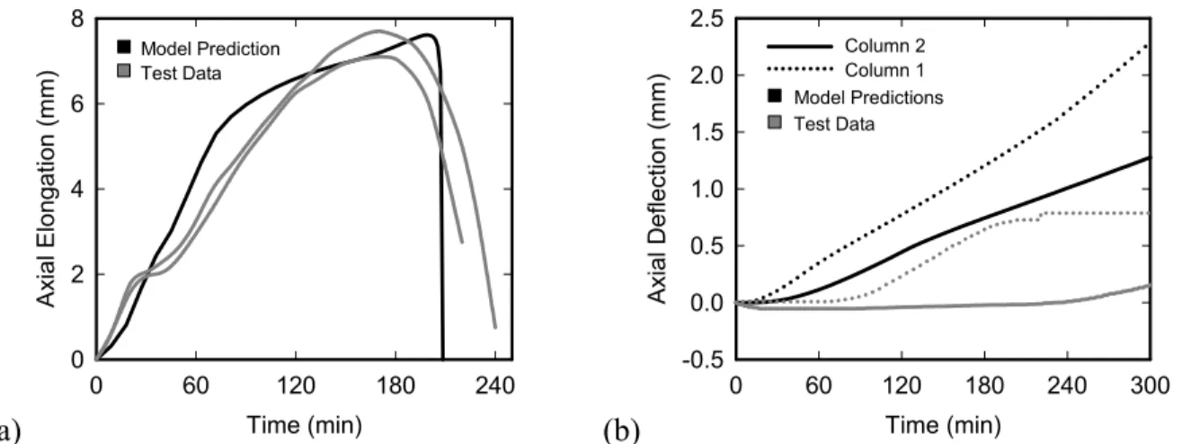
Figure 10a shows the measured and predicted axial deformation of columns 1 and 2 (unwrapped columns) as a function of fire exposure time under an applied compressive load of 1431 kN. During the first two hours of exposure, the predicted deformation is generally slightly greater than that observed in tests. This could be due to the short term creep of the concrete or to the seating effects not accounted for in the model, both of which would tend to decrease the observed deformation. However, both the maximum deformation and the point of failure are predicted reasonably well by the model. The greatest difference between predicted and measured axial deformation is in the order of 1.5 mm, which is satisfactory in comparison to the overall elongation of the columns (≈7.5 mm). Axial deformation of the members is influenced by a number of factors, including thermal expansion, load effects, short-term thermally induced creep, and bending, some of which cannot be completely accounted for by the model. Nonetheless, the model adequately predicts the overall magnitude of elongation when compared against test data.
Figure 10b shows the measured and predicted axial deformations of columns 7 and 8 (insulated FRP-wrapped columns) as a function of fire exposure time under an applied axial load of 2515 kN. The model over-predicts the expansion of both columns for the full length of fire exposure. Nonetheless, the largest difference between predicted and measured axial deformation is in the order of 1.5 mm, which is small in comparison to the overall length of the columns. Given the extremely small magnitude of the deformations, both predicted and observed, it is difficult to state conclusively whether the model is an adequate predictor of axial elongation for insulated FRP-wrapped columns.
(a) Time (min)
0 60 120 180 240 A x ial Elongat io n (m m) 0 2 4 6 8 Model Prediction Test Data (b) Time (min) 0 60 120 180 240 300 Axial Def lect ion (mm) -0.5 0.0 0.5 1.0 1.5 2.0 2.5 Model Predictions Test Data Column 2 Column 1
FIGURE 10 : Predicted and observed column deformations during fire tests by (a) Lie and Celikkol [12] and (b) Bisby [15].
CONCLUSIONS
In this paper, a numerical model was described that can be used to predict the behaviour of circular insulated and FRP-confined RC columns to exposure to a standard fire. The model has
been verified against data from fire endurance tests on RC columns available in the literature and from tests on insulated FRP-wrapped columns performed by the authors. The model agrees reasonably well with experimental results.
With respect to the fire performance of FRP-wrapped columns, the model suggests that it will likely be very difficult, within the practical range of insulation thicknesses, to maintain the confining effectiveness of an FRP wrap during fire. If fire endurance is defined in terms of the load-carrying capacity of the column, as it should be according to current North American fire endurance guidelines, then the FRP wrap should likely be considered ineffective during fire. However, supplemental insulation applied to the exterior of the wrap is capable of dramatically improving the structural fire endurance of the overall column. Thus, satisfactory fire endurance of FRP-wrapped RC columns can be ensured by providing supplemental fire insulation and limiting the allowable strength increases due to FRP wrapping, as discussed above.
REFERENCES
[1] Bisby, L.A., Dent, A.J.S, & Green, M.F. A comparison of models for FRP-confined concrete, Accepted, Journal of Composites for Construction, American Society of Civil
Engineers, New York, USA, 9 pp. (2004).
[2] ISIS Canada, Design Manual No. 4, Intelligent Sensing for Innovative Structures,
Winnipeg, Canada, 2001.
[3] CAN/CSA, CSA-S806-02: Design and construction of building components with fibre-reinforced polymers, Canadian Standards Association, Ottawa, Canada, 2002.
[4] ACI, ACI 440.2R-02, American Concrete Institute, Farmington Hills, USA, 2002.
[5] The Concrete Society, Technical Report 55: Design guidance for strengthening concrete structures using fibre-composite materials, The Society, London, UK, Crowthorne, 2000.
[6] Karbhari, V., Chin, J., Hunston, D., Benmokrane, B., Juska, T., Morgan, R., Lesko, J.J., Sorathia, U., & Reynaud, U., Durability gap analysis for fibre-reinforced polymer composites in civil infrastructure, Journal of Composites for Construction, 7, N˚ 3,
American Society of Civil Engineers, New York, USA, pp. 238-247 (2003).
[7] Harries, K., Porter, M., & Busel, J., FRP materials and concrete - research needs,
Concrete International, 25, N˚ 10, American Concrete Institute, pp. 69-74 (2003).
[8] Spolestra, M., & Monti, G., FRP-confined concrete model, Journal of Composites for
Construction, 3, N˚ 3, American Society of Civil Engineers, New York, USA, pp. 143–150 (1999).
[9] Blontrock, H., Taerwe, L., & Vandevelde, P., Fire testing of concrete slabs strengthened with fibre composite laminates, FRPRCS-5, Thomas Telford Ltd, London, pp. 547-556
(2001).
[10] ASTM, Test Method E119-01, American Society for Testing and Materials, West
Conshohocken, USA, 21 pp., 2001.
[11] CAN/ULC, CAN/ULC-S101-M89, Underwriters’ Laboratories Canada, Scarborough,
Canada, 49 pp., 1989.
[12] Lie, T.T. & Celikkol, B., Method to calculate the fire resistance of circular reinforced concrete columns, ACI Materials Journal, 88, N˚ 1, American Concrete Institute,
[13] Lie, T., Structural Fire Protection, American Society of Civil Engineers, New York, USA,
241 pp., 1992.
[14] ACI, ACI 318-95: Building code requirements for structural concrete, American Concrete
Institute, Farmington Hills, USA, 1995.
[15] Bisby, L., Fire behaviour of fibre-reinforced polymer reinforced or confined concrete,
Ph.D. Thesis, Department of Civil Engineering, Queen’s University, Kingston, Canada, 371 pp., 2003.
[16] Griffis, C.A., Masmura, R.A., & Chang, C.I. Thermal response of graphite epoxy composite subjected to rapid heating, Environmental Effects on Composite Materials, V.
2, Technomic, Lancaster, USA, pp. 245-260, 1984.
[17] Dimitrienko, Y.I., Thermomechanics of composites under high temperatures. Klewer
Academic Publishers, London, UK, 347 pp., 1999.
[18] Franssen, J.-M. & Dotreppe, J.-C., Fire tests and calculation methods for circular concrete columns, Fire Technology, Klewer Academic Publishers, London, UK, 39, pp. 89-97
(2003).
ACKNOWLEDGEMENTS
The authors are members of the Intelligent Sensing for Innovative Structures Network (ISIS Canada) and wish to acknowledge the support of the Networks of Centres of Excellence Program of the Government of Canada and the Natural Sciences and Engineering Research Council of Canada. The authors would also like to acknowledge the financial contributions of the National Research Council of Canada and Queen’s University, Canada.
![FIGURE 1 : Typical effects of FRP confinement on circular reinforced concrete columns [8]](https://thumb-eu.123doks.com/thumbv2/123doknet/14190462.477910/5.918.137.428.538.774/figure-typical-effects-confinement-circular-reinforced-concrete-columns.webp)


![FIGURE 7 : Assumed variation in (a) strength and (b) stiffness of FRP with temperature (based on semi-empirical regression analysis performed by Bisby [15])](https://thumb-eu.123doks.com/thumbv2/123doknet/14190462.477910/11.918.140.805.748.996/assumed-variation-strength-stiffness-temperature-empirical-regression-performed.webp)

![FIGURE 8 : Predicted and observed temperatures at various locations during fire tests by (a) Lie and Celikkol [12] and (b) Bisby [15]](https://thumb-eu.123doks.com/thumbv2/123doknet/14190462.477910/13.918.157.826.387.639/figure-predicted-observed-temperatures-various-locations-celikkol-bisby.webp)