DOI 10.1007/s11517-013-1120-z
SPECIAL ISSUE - ORIGINAL ARTICLE
Towards the development of a novel experimental shoulder
simulator with rotating scapula and individually controlled
muscle forces simulating the rotator cuff
Daniel Baumgartner · Daniel Tomas · Lukas Gossweiler · Walter Siegl · Georg Osterhoff · Bernd Heinlein
Received: 10 December 2012 / Accepted: 7 October 2013 / Published online: 30 October 2013 © International Federation for Medical and Biological Engineering 2013
angle of 85°. The rotating scapular part driven by a rota-tive electro actuator provides one-third to the overall arm abduction. Resulting joint forces and moments are meas-ured by a 6-axis load cell. A linear increase in the DELT and SSP motors is shown up to a maximum of 150 and 50 N for the DELT and SSP, respectively. The force vector in the glenoid resulted in 253 N at the maximum abduc-tion. The present investigation shows the contribution of individual muscle forces attached to the moving humerus to perform active abduction in order to reproducibly test shoulder implants.
Keywords Shoulder biomechanics · Experimental
testing · Muscle force analysis · Glenohumeral joint force
1 Introduction
The human shoulder joint with its large range of motion (ROM) and high number of muscles is one of the most complex joints in the human body. The shoulder is char-acterised by specific biomechanical attributes, distinctive from other joints in the skeletal system: the unconstrained geometry of the glenohumeral (GH) joint with a small articulating surface enables a high range of motion. The tendons of the shoulder muscles are wrapped around the spherical humeral head. Third, the scapular rotation relative to the thorax contributes to the abduction range of motion. Developing an experimental shoulder model which repro-duces kinematic and kinetic conditions at the glenohumeral joint is therefore highly requested. However, realistic experimental biomechanical conditions close to physiology are necessary to test implants or operation procedures. Up till now, no experimental testing method has been consid-ered as an approved standardised model; existing shoulder
Abstract A preclinical analysis of novel implants used in
shoulder surgery requires biomechanical testing conditions close to physiology. Existing shoulder experiments may only partially apply multiple cycles to simulate postopera-tive, repetitive loading tasks. The aim of the present study was therefore the development of an experimental shoulder simulator with rotating scapula able to perform multiple humeral movement cycles by simulating individual mus-cles attached to the rotator cuff. A free-hanging, metallic humerus pivoted in a polyethylene glenoid is activated by tension forces of linear electroactuators to simulate muscles of the deltoideus (DELT), supraspinatus (SSP), infraspina-tus/teres minor and subscapularis. The abductors DELT and SSP apply forces with a ratio of 3:1 up to an abduction
D. Baumgartner (*) · D. Tomas · L. Gossweiler · B. Heinlein IMES Institute of Mechanical Systems, Zurich University of Applied Sciences ZHAW, Technikumstrasse 9, 8401 Winterthur, Switzerland e-mail: [email protected] D. Tomas e-mail: [email protected] L. Gossweiler e-mail: [email protected] B. Heinlein e-mail: [email protected] W. Siegl
IEFE Institute of Energy Systems and Fluid Engineering, Zurich University of Applied Sciences ZHAW, Technikumstrasse 9, 8401 Winterthur, Switzerland
e-mail: [email protected] G. Osterhoff
Division of Trauma Surgery, University Hospital Zurich USZ, Zurich, Switzerland
models introduce predefined loads which are in contrast to muscle loads resulting from actively levering a free-hang-ing arm. A brief literature analysis is therefore important to give an overview about existing experimental shoulder test-ing and its limitations.
Generally, shoulder models with a free-hanging humerus are stabilised by tension loads applied by electroactua-tors to the rotator cuff tendons to activate the humerus in abduction. Such a model was developed by Wuelker et al. [27] to determine the rotator cuff muscle force distribu-tion. The effect of rotator cuff forces on GH joint stability was assessed by performing abduction, while the scapula was fixed. To determine the GH contact area, a cadaver test set-up was realised by Soslowsky et al. [21]. Applied loads were derived based on clinical, anatomical and mechani-cal data from literature [17]. A similar model was also used by Karduna et al. [11] to measure the influence of articular geometry on the GH joint forces. However, such models are developed to analyse biomechanical loading conditions at the musculoskeletal system for static positions in equi-librium. Repetitive loading cycles to apply a loading sce-nario for primary stability testing of prosthesis are not pos-sible by using such models.
Other models used different muscle loading protocols applied by servo-hydraulic actuators through cable–pulley systems to evaluate resulting motion pathways, such as the models of Kedgley et al. [13], Bono et al. [3] or Debsky et al. [6]. Sharkey et al. [19] created a set-up to vary the humeral position by adjusting glenohumeral and scapulo-thoracic rotation. A ratio of 3:2 between glenohumeral and scapulothoracal abduction angle was maintained through-out the experiment.
Abu Rajab et al. [1] performed a testing of a fractured proximal humerus by muscular loading of the rotator cuff. The movement of the tuberosities relative to the humeral shaft was analysed. A similar study by De Wilde et al. [5] tested the fracture reconstruction stability using a tension test. Smith et al. [20] determined the strength of arthro-scopic rotator cuff repair during cyclic testing. In particu-lar, forces were introduced for a fixed position of 30° GH abduction to the rotator cuff tendons. Mentioned models would allow a cyclic testing of a shoulder joint in contrast to previous models, but an active arm motion is not real-ised due to the fixation of the humeral shaft. Nevertheless, a moving humerus which alternates the force direction is needed to simulate everyday loading tasks which obvi-ously occur in a postoperative situation during the recovery phase.
Nyffeler et al. [15] analysed the influence of the ante-version/retroversion angle of the glenoid component on the humeral head displacement. Application of a constant force of 20 N to each rotator cuff tendon was performed during elevation. From literature, it is known that the rotator cuff
load achieves 200 N tension during an abduction cycle just with the single arm weight. Forces applied during testing are often in a lower range compared to real data.
Harryman et al. [10] also applied a manual GH ele-vation up to a maximum torque of 3 Nm to analyse the humeral head translation. Novotny et al. [14] investigated motion patterns of the GH joint for an unconstrained movement. This technical solution is unique in the field of experimental shoulder testing. In the set-up, a force couple, produced by air jets, induced free-floating torque to analyse kinematic behaviour of a free-hanging, uncon-strained humerus.
Anatomical versus non-anatomical reconstruction was performed in one of the experimental tests by Frankle et al. [8]. A robot applied angular controlled internal/external rotation done at a constant rate of 10° per second until a maximum angle of 50°. Angular controlled rotation showed higher resulting torques for a non-anatomical fragment fixation at the prosthesis shaft. Similar to previous study, Werner et al. [23] applied 1 Nm step-wise loading to a maximum value of 4 Nm. Testing was done in 0° abduc-tion; predetermined fixed abduction angles of 30° and 60° were applied. The measurement of strains at the inferior GH ligament by combining constant muscular tension with a force couple distally at the humerus was taken by Cain et al. [4]. Muscle forces were randomly varied by different loading step increments.
In a study by Williams et al. [25], forces of 30 N were applied at each rotator cuff tendon. By increasing tensional forces of SSC and ISP, respectively, internal/external rota-tions were measured. The function of the SSC muscle in case of anterior humeral head subluxation was evaluated by Werner et al. [24]. Lines of action of the SSC segments were evaluated during an anterior–inferior displacement for three different arm positions.
Yu et al. [28] determined the inferior shift of the humeral head in a healthy condition and with a full-thickness supraspinatus (SSP) tear by maintaining a specific muscle force ratio of 3:2 between the DELT and SSP.
To summarise mentioned studies, scapular rotation is simulated only by one of present models from the literature. It is therefore of high interest to involve active scapular rotation with individual muscular loading in an experimen-tal model in order to achieve a model closer to physiology. Furthermore, it is generally known that a lot of prosthesis fails within 3 months in vivo postoperatively. A simulator which is able to perform cyclic loading could simulate such repetitive motion, which is up till now just fulfilled by uni-directional muscular tension applied by standardised test-ing machines. In addition, the simulator has the benefit of simulating real frictional behaviour of implanted, articulat-ing glenospheres, which could be used as boundary condi-tion in computer models.
The aim of the present study is the development of a physiological, experimental shoulder simulator able to per-form repetitive, reproducible humeral movements to assess primary stability testing of prosthesis designs. To achieve predefined glenohumeral angles, individual muscle forces are controlled in a real-time closed-loop control.
2 Material and methods
2.1 General description of the shoulder simulator
2.1.1 Muscle forces
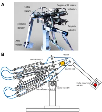
A free-hanging humerus made of stainless steel pivoted in the artificial glenoid is activated by linear electroactua-tors to exert forces on the rotator cuff. Tension forces of the actuators (Maxon Motor AG, Switzerland) are trans-ferred by a cable–pulley system to the humerus, simulat-ing the muscles deltoideus (DELT), SSP, infraspinatus/teres minor (ISP/TM) and subscapularis (SSC), seen in Fig. 1a, b. These spindle motors are used to apply a displacement-controlled constant speed, resulting in a tension force at the DELT and SSP. Due to an increasing lever arm of the arm weight, the tensional loads are increasing parallel with the abduction angle. A constant ratio of 3:1 between DELT and SSP is maintained throughout the whole abduc-tion cycle, which was defined based on the publicaabduc-tion of Sharkey et al. The simulator is able to achieve abduction angles up to 85°. The anterior shoulder muscle (SSC) and the posterior shoulder muscles (ISP/TM) at the proximal humerus are loaded symmetrically with a constant force of 30 N each. The SSC muscle is divided into two segments; one insertion is placed 10 mm superior to the humeral head centre and the other insertion 10 mm below the head cen-tre. A cocontracting effect of the superior abductor and inferior adductor is expected. Symmetric configuration has been chosen for the ISP/TM segments. The arm weighs 2.5 kg, which corresponds to an arm weight from the lit-erature [6]. The artificial humerus head has a diameter of 70 mm, whereas the head centre is medially displaced 7 mm from the humerus axis. The humeral head radius has been extended by 20 mm in comparison with a stand-ard value of 50 mm. This has been done to reproduce the muscular line of action, which is defined as the middle fibre of a wrapped muscle with a certain thickness. Given that such a middle fibre of the muscle is 10 mm in distance to the humeral surface due to muscular thickness, the humeral head radius has been increased by 10 mm, resulting in a radius of 35 mm.
The humerus has a total length of 308 mm. The centre of mass is located at a distance of 185 mm from the artificial glenosphere centre.
2.1.2 Scapular rotation
The scapula motor (SM) rotates the scapula actively according to the humerus movement and contributes one-third of the overall arm abduction. The motor of the scapula resulted in a superior shifting of the glenohumeral joint during abduction. The placement of the electroactuator for scapular rotation has no influence on the relative position of the GH joint.
2.2 Controlling mechanisms of the humeral movement The artificial humeral bone is controlled in the scapular plane by the CR control circuit (control of rotation: CR). The abduction angle is simultaneously controlled by the CA control circuit (control of abduction: CA). Both con-trol loops are configured by a corresponding master/slave branch. Four linear and one rotational drive for the scap-ula are cascaded to their corresponding controllers. The humeral motion is measured by a 6-DOF inertial measure-ment unit (IMU) mounted distally on the humerus dummy. Suitable processing of the IMU signals yields the abduction
Fig. 1 a The shoulder simulator is presented in an anteriolateral view. A free-hanging humerus is activated by tensional forces of electroactuators through cable pulleys. The actuators are fixed at the scapular part to counteract the humeral load of 2.5 kg. As a conse-quence, the simulator is balanced in an equilibrium. b Frontal view of the simulator in the scapular plane. The motors apply tensional forces to the tendons to activate the humerus. Due to the symmetric set-up, motor 1 and 3 are placed at the front side and motor 2 and 4 at the rear side of the simulator
angle (alpha) and the rotation angle (beta) of the current humerus position.
2.2.1 Abduction control circuit
The abduction control loop is shown in Fig. 2. The abduc-tion angle set by the user is compared to the currently measured alpha angle from the IMU unit. The correspond-ing controller for abduction determines the command posi-tion for the master linear drive of the DELT muscle. The resulting tension is measured by an unidirectional load cell LC1 (NBN Elektronik AG, Switzerland). The slave CA controller determines the command force to the Slave lin-ear drive of the SSP. Both actuators transfer tension forces by wrapped cables around the spherical humerus head to the shaft. The command signals for the SSP muscle force during abduction (SCA) are derived from the actual meas-ured LC1 and LC2 values.
2.2.2 Rotational control circuit
The rotational circuit (CR) is needed to keep the humeral axis in the scapular plane (Fig. 3). The current beta angle is compared with a target value, set by the user. The result-ing error signal is fed to the MCR controller which deliv-ers the position command signal to the linear drive of the Master CR (corresponding to infraspinatus/teres minor) whose output is mechanically connected to the anterior side of humerus by cables wrapped around the humeral head. The resulting tension applied by the motor is measured by the load cell LC3. A similar configuration is available for the Slave CR (corresponding to the SSC muscle). The
controller gives a force command signal to the correspond-ing drive which is mechanically connected to the angle alpha. The tension is measured by the load cell LC4. The current feedback signal of this loop is half of both meas-ured tensions from the load cells LC3 and LC4.
2.3 Measurement devices
Joint forces acting orthogonally and laterally to the artifi-cial glenoid are measured by a 6-axis load cell (Transme-tra GmbH, Germany). By means of all three vector com-ponents, the resultant force vectors in the glenoid were determined during a sequence of eight subsequent abduc-tion cycles. Muscle and joint forces were acquired in 15° incremental steps during abduction. Based on 8 subsequent cycles, standard deviations were evaluated for each meas-urement points.
The single muscle forces are controlled by unidirectional load cells (Transmetra GmbH, Germany). Controlling the muscles and data acquisition were performed by a real-time target combined with LabVIEW software (National Instru-ments, US).
3 Results
3.1 Glenohumeral muscle forces
Generally, the muscular force slopes of SSP and DELT are characterised by a hysteresis curve during the increase in the abduction angle. The DELT muscle force is seen in Fig. 4, the SSP muscle force in Fig. 5. At low abduction angles, the lever arm of the arm weight increases initially to a higher extent per angular unit and follows therefore a nonlinear behaviour. A slight flattening of the DELT
Fig. 2 Control circuit controlling the abduction movement (CA). An IMU is used at the distal end of the humerus to control the current abduction angle
Fig. 3 Control circuit controlling the rotational movement around the longitudinal axis of the humerus (CR). Maintaining the humerus in the scapular plane prevents an unstable movement
muscle force is detected between 75° and 85°, which can be explained by the detachment from the humeral head and increase in the muscular lever arm. Generally, higher muscle forces are necessary for abduction than during the adduction cycle, because friction is counteracting the abduction movement.
Data from the literature resulting from computer simula-tion models [7, 12, 16, 22] show higher muscle forces com-pared to experimental analysis [18, 19, 26]. In the present tests with the novel simulator, the DELT muscle force is in the range of existing experiments and achieves a maximum force of 150 N. An almost linear increase in the muscle force with respect to the abduction angle is detected for all experi-ments. SSP forces in the experiment almost match the data of Roetman et al. [18] and show increase up to a maximum of 50 N, which proves the correct muscle force ratio of 3:1.
Instability of the humerus by moving out of the scapular plane was detected for single cycles, if the centre of gravity
of the arm weight was not attached centrally in the scapu-lar plane. Maximum muscle forces vary within a stand-ard deviation of 2–8 %. Such results can be considered as reproducible, because similar variability had been detected in studies from the literature [19, 26].
3.2 Glenohumeral joint forces
The resulting vector in the polyethylene glenoid is at the lower range in the present study compared to the values in the literature [2, 9, 16, 22] and reaches a maximum of 260 N for moving an arm weight of 2.5 kg (Fig. 6). Con-trary to the lower values at maximum abduction, the cur-rent study starts with an initial force of 100 N, which was necessary to maintain glenohumeral stability and to pre-vent subluxation of the humeral head. A hysteresis curve is detected for an abduction/adduction cycle, which is similar to the data of Bergmann et al. [2].
3.3 Steering mechanism and closed-loop control
After first measurements, the realised system is able to perform the predefined boundary conditions. The master motor representing the DELT and slave motor representing the SSP are in the predefined ratio of 3:1.
After first measurements, one abduction cycle 0°–85°– 0° needs 6 s. Especially for long-term testing, the cycle time still needs to be reduced in order that a statistically significant amount of prosthesis may be tested within an efficient time range.
4 Discussions
The muscle forces of SSP and DELT of the present simu-lator match the data delivered in the literature. However,
Fig. 4 Deltoideus muscle forces for one adduction/abduction cycle compared to the literature (abduction pink, adduction red coloured) (colour figure online)
Fig. 5 Supraspinatus muscle forces for one adduction/abduction cycle compared to the literature (abduction pink, adduction red col-oured). Asterisk in the present graphs, the measured results are com-pared to results of other biomechanical experimental results in the literature (blue curves “exp.”) and to computer simulation models (black curves “sim.”) (colour figure online)
Fig. 6 Glenohumeral joint forces for one adduction/abduction cycle (abduction pink, adduction red coloured) (colour figure online)
lower values than in the literature were detected for the glenohumeral joint load. Consequently, the lateral shoulder muscles should have a linear ascending force characteris-tic instead of the constant force of 30 N. This would have positive effect to increase the joint load for higher abduc-tion angles. Furthermore, the higher in vivo joint loads of Bergmann et al. could be explained by a higher activation of the rotator cuff muscles due to stabilising effects, in addition to just mobilise the arm weight. The missing sta-bility becomes visible, if the arm weight is not placed sym-metrically and therefore leading to subsequent instability at higher abduction angles.
For a better stabilisation of the humerus in the scapular plane, the additional implementation of the muscles pecto-ralis and latissimus is needed.
The force ratio of DELT:SSP should be 3:1, whereas a ratio of 6:1 was detected initially at low abduction angles. This circumstance shows that the ratio cannot be con-trolled very well for low abduction angles with low tension forces. Nevertheless, the force ratio for higher abduction angles matches the target value of 3:1, which is of higher relevance for the forces at a higher level. The size of the spherical humerus needs to be discussed, which directly influences the muscular lever arms: If the diameter of the sphere is reduced, a linear increase in the muscle forces to physiological loading level will occur.
To achieve the mentioned limit, the CA system has to be made faster without reducing the currently gained accuracy. Finally, a combination of abduction and rotation will be in the focus for further investigations. Independent angles for the single planes need to be detected by the IMU.
5 Conclusions
In the present investigation, an experimental shoulder has been built to perform basic biomechanical analysis or to test prosthesis systems at the human shoulder. The described technology is able to fulfil the requirements of a test set-up simulating postoperative conditions of early arm mobilisation and has specific features in compari-son with existing testing devices from the literature: the scapular rotation contributes to overall arm abduction. Muscular tensional loads are introduced to the proximal humerus driven by electroactuators to simulate the rota-tor cuff, the DELT and the SSP. Third, the glenohumeral joint and muscle loads are measured individually by load cells. First promising results were generated which prove the reliability and repeatability of the testing device to test prosthesis systems under conditions close to physiology. However, limitations of the simulator need to be addressed and improved in a further optimisation step. Additional muscles such as the pectoralis or the latissimus would
provide additional stability. As cocontractors of the SSP and DELT, the GH joint force would be increased. The effect of a moving scapula on the GH joint force direction in comparison with a fixed scapula needs to be analysed more in detail to prove whether this additional function does lead to different results.
References
1. Abu-Rajab RB et al (2006) Re-attachment of the tuberosities of the humerus following hemiarthroplasty for four-part fracture. J Bone Joint Surg Br 88(11):1539–1544
2. Bergmann G et al (2007) In vivo glenohumeral contact forces— measurements in the first patient 7 months postoperatively. J Bio-mech 40(10):2139–2149
3. Bono CM et al (2001) Effect of displacement of fractures of the greater tuberosity on the mechanics of the shoulder. J Bone Joint Surg Br 83(7):1056–1062
4. Cain PR et al (1987) Anterior stability of the glenohumeral joint. A dynamic model. Am J Sports Med 15(2):144–148
5. De Wilde LF et al (2004) A new prosthetic design for proximal humeral fractures: reconstructing the glenohumeral unit. J Should Elbow Surg 13(4):373–380
6. Debski RE et al (1995) A new dynamic testing apparatus to study glenohumeral joint motion. J Biomech 28(7):869–874
7. Favre P et al (2005) An algorithm for estimation of shoulder muscle forces for clinical use. Clin Biomech (Bristol, Avon) 20(8):822–833
8. Frankle MA et al (2001) Biomechanical effects of malposition of tuberosity fragments on the humeral prosthetic reconstruction for four-part proximal humerus fractures. J Should Elbow Surg 10(4):321–326
9. Gupta S, van der Helm FC (2004) Load transfer across the scap-ula during humeral abduction. J Biomech 37(7):1001–1009 10. Harryman DT II et al (1990) Translation of the humeral head on
the glenoid with passive glenohumeral motion. J Bone Joint Surg Am 72(9):1334–1343
11. Karduna AR et al (1996) Kinematics of the glenohumeral joint: influences of muscle forces, ligamentous constraints, and articu-lar geometry. J Orthop Res 14(6):986–993
12. Karlsson D, Peterson B (1992) Towards a model for force predic-tions in the human shoulder. J Biomech 25(2):189–199
13. Kedgley AE et al (2007) The effect of muscle loading on the kinematics of in vitro glenohumeral abduction. J Biomech 40(13):2953–2960
14. Novotny JE, Nichols CE, Beynnon BD (1998) Normal kin-ematics of the unconstrained glenohumeral joint under coupled moment loads. J Should Elbow Surg 7(6):629–639
15. Nyffeler RW et al (2006) Effects of glenoid component ver-sion on humeral head displacement and joint reaction forces: an experimental study. J Should Elbow Surg 15(5):625–629 16. Oizumi N et al (2006) Numerical analysis of cooperative
abduc-tion muscle forces in a human shoulder joint. J Should Elbow Surg 15(3):331–338
17. Perry J (1983) Anatomy and biomechanics of the shoulder in throwing, swimming, gymnastics, and tennis. Clin Sports Med 2(2):247–270
18. Roetman B, Wuelker N, Plitz W (1996) A dynamic shoulder model for biomechanical measurements of shoulder specimen. Biomed Tech (Berl) 41(12):359–363
19. Sharkey NA, Marder RA, Hanson PB (1994) The entire rota-tor cuff contributes to elevation of the arm. J Orthop Res 12(5):699–708
20. Smith CD et al (2006) A biomechanical comparison of single and double-row fixation in arthroscopic rotator cuff repair. J Bone Joint Surg Am 88(11):2425–2431
21. Soslowsky LJ et al (1992) Quantitation of in situ contact areas at the glenohumeral joint: a biomechanical study. J Orthop Res 10(4):524–534
22. van der Helm FC (1994) A finite element musculoskeletal model of the shoulder mechanism. J Biomech 27(5):551–569
23. Werner CM et al (2004) The effect of capsular tightening on humeral head translations. J Orthop Res 22(1):194–201
24. Werner CM, Favre P, Gerber C (2007) The role of the subscap-ularis in preventing anterior glenohumeral subluxation in the abducted, externally rotated position of the arm. Clin Biomech (Bristol, Avon) 22(5):495–501
25. Williams GR Jr et al (2001) The effect of articular malposition after total shoulder arthroplasty on glenohumeral translations, range of motion, and subacromial impingement. J Should Elbow Surg 10(5):399–409
26. Wuelker N et al (1995) A dynamic shoulder model: reliability testing and muscle force study. J Biomech 28(5):489–499 27. Wuelker N, Korell M, Thren K (1998) Dynamic glenohumeral
joint stability. J Should Elbow Surg 7(1):43–52
28. Yu J et al (2005) Biomechanical effects of supraspinatus repair on the glenohumeral joint. J Should Elbow Surg 14(1 Suppl S):65S–71S