Design of Low Cost Biomimetic Flexible Robots
Using Additive Manufacturing Techniques
by
Eric J.S. Jeunehomme
B.Eng., Mechanical Engineering
Royal Military College of Canada (2013)
Submitted to the Department of Mechanical Engineering
in partial fulfillment of the requirements for the degrees of
Master of Science in Naval Architecture and Marine Engineering
and
Master of Science in Mechanical Engineering
at the
MASSACHUSETTS INSTITUTE OF TECHNOLOGY
June 2019
@
Massachusetts Institute of Technology 2019. All rights reserved.
Author...
Certified by..
Accepted by ... MASSACHUSETT INSTITUTE OF TECHN LOGYJUN 132019
UBRARIES
Signature redacted
Department of Mechanical Engineering
I
May 10, 2019
...
Signature redacted
Alexandra H. Techet
Professor of Ocean Mechanical Engineering
Signature redacted
Thesis Supervisor
...Nicolas Hadjiconstantinou
hairman, Department Committee on Graduate Theses
77 Massachusetts Avenue
Cambride, MA 0213q
M
ITubrarnes
uas
MIT~ibarieshttp://Iibraries.mit.edu/ask
DISCLAIMER NOTICE
The pagination in this thesis reflects how it was delivered to the Institute Archives and Special Collections.
Design of Low Cost Biomimetic Flexible Robots Using
Additive Manufacturing Techniques
by
Eric J.S. Jeunehomme
Submitted to the Department of Mechanical Engineering on May 10, 2019, in partial fulfillment of the
requirements for the degrees of
Master of Science in Naval Architecture and Marine Engineering and
Master of Science in Mechanical Engineering
Abstract
In this thesis, I designed and fabricated robots leveraging additive manufacturing. This had two overarching purpose. One to make a testing apparatus that would allow the measurements of the influence of a flexible flapping foil onto a subsequent, in-line, foil with the optic of researching optimized propulsion solutions for under water vehicles. The second was to show that filament deposition modeling has advanced enough to produce bio-mimetic flexible robots of academic relevance that would allow, for a low price, the making of a number of experimental setup with specific measurements in mind. In order to reach those goals, two versions of a bio-mimetic archer fish of the genus Toxotes were modeled using various software. The models were modified to accept actuator assemblies and interface to the electronics and built using a modified hobby grade 3D printer.
Thesis Supervisor: Alexandra H. Techet
Acknowledgments
I would like to express my appreciation and gratitude towards:
Professor Alexandra Techet for her help and guidance in all aspect of this project. Your input was invaluable to my success.
The Canadian Armed Forces and Royal Canadian Navy for their dedication to continued education and improvement of their members. Their support through programs and funding makes a large positive difference in the type of academic life one would experience.
My family and spouse for the constant emotional support and motivation. Your
encouragements helped me reach my potential.
Austin, Nicole, MacKenzie, and Gabriel Jolley. You, my friends, acted as my surrogate family while I was away here in Cambridge and I will cherish those times we spent together.
Contents
1 Introduction 15 2 Background 17 2.1 Biomimetics . . . . 17 2.1.1 Robotuna . . . . 17 2.1.2 Knife Fish . . . . 192.1.3 Compliant Fish Robot Design . . . . 19
2.1.4 Fish Locomotion . . . . 21
2.1.5 Analytical Thrust Determination . . . . 22
2.2 Pre-swirling Stator . . . . 28 2.3 Applications . . . . 29 2.3.1 UUV Manoeuvrability . . . . 29 2.3.2 Signature of UUVs . . . . 29 3 Design 31 3.1 Design . . . . 31
3.1.1 Obtaining the body shape . . . . 32
3.1.2 Component selection . . . . 35
3.1.3 Body modifications . . . . 37
4 Fabrication 41 4.1 Additive Manufacturing . . . . 41
4.1.2 Truing . . . . 43
4.2 Operations . . . .. . . . 44
4.3 Assembly . . . . 47
4.3.1 Waterproofing Stepper Motors . . . . 48
4.3.2 Assembling the motion units . . . . 50
4.3.3 Fastening the units to the shell . . . . 52
4.3.4 Affixing the head . . . . 52
4.3.5 W iring the motors . . . . 53
4.3.6 Closing the shell . . . . 53
4.3.7 Finishing . . . . 54
5 Results 55 5.1 Applying the process to other designs . . . . 55
5.2 C ost . . . . 58
6 Conclusion 61 A Part List 63 A.1 Slim ArcherBot . . . . 63
A.2 Average ArcherBot . . . . 82
A.3 Robot Turtle Quick Design Test . . . . 97
A.4 2 DOF In-line Foil on Foil Interaction Robot . . . . 100
B CR-10 Modifications 103 B.0.1 Direct Extruder . . . . 103 B.0.2 Upgrade to Firmware . . . . 104 B.0.3 Other modifications . . ... . . . . 104 B.0.4 Recommendation . . . . 105 C Arduino Code 107
List of Figures
2-1 2-2 2-3 2-4 Concept of Robotuna [1] . . . .CAD Model of a Knifefish like robot [2] . . . .
(a) BCF, and (b) MPF propulsion modes [3] . . . . Curves of thrust, torque, and efficiency for a propeller in open water [4]
2-5 Laying KT,ship curve on a open water diagram from
[4]
. . . .2-6 Velocity and Force diagram for a particular radial position on a lifting
lin e [5 ] . . . .
2-7 Wsrtsilsd Pre-swirl Stator Concept [6] . . . . 3-1 Adequate Baseline Picture of an Archerfish [7] . . . .
3-2 Body trace of an archerfish . . . . 3-3 Lofted body of a slim archerfish model . . . .
3-4 Fin modeling process . . . .
3-5 Starting body of the Slim Archerbot . . . .
3-6 The four size of tested steppers . . . . 3-7 Wiring diagram for the stepper drivers . . . . 3-8 Section view of the Archerbot . . . .
3-9 Profile comparison of the live fish vs the average variant
4-1 Slim Archer shell warping under tension due to cooling 4-2 The trialed methods of printing fins . . . . 4-3 Back shell mid-print . . . . 4-4 Parts of the NEMA11 motors . . . . 4-5 The four main water ingress points of NEMAl . . . . .
18 19 21 22 25 26 28 . . . . 32 . . . . 33 . . . . 34 . . . . 35 . . . . 35 . . . . 36 . . . . 37 . . . . 38 . . . . 39 . . . . 44 . . . . 46 . . . . 47 . . . . 48 . . . . 49
4-6 Waterproofed Motor . . . . 50
4-7 Assembled Motion Units Ready for Testing . . . . 52
4-8 Archerbot with Motors Wired . . . . 53
4-9 Finished Slim Archerbot . . . . 54
5-1 CAD model of a robotic turtle using the design of [8] . . . . 56
5-2 In-Line Fin Overlap for the archerfish . . . . 57
5-3 Non-biomimetic robot for foil on foil interaction . . . . 57
A-1 Slim ArcherBot . . . . 64
A-2 Slim ArcherBot Head . . . . 65
A-3 Slim ArcherBot Back . . . . 66
A-4 Slim ArcherBot Dorsal Fin . . . . 67
A-5 Slim ArcherBot Anal Fin . . . . 68
A-6 Slim ArcherBot Fwd Anal Fin Mount . . . . 69
A-7 Slim ArcherBot Aft Anal Fin Mount . . . . 70
A-8 Slim ArcherBot Caudal Fin . . . . 71
A-9 Slim ArcherBot Caudal Fin Mount . . . . 72
A-10 Slim ArcherBot Spine Mount . . . . 73
A-11 Slim ArcherBot Spine Pivot . . . . 74
A-12 Slim ArcherBot Fin Lever . . . . 75
A-13 Slim ArcherBot 5mm Bore Bevel Gear . . . . 76
A-14 Slim ArcherBot 9mm Bore Bevel Gear . . . . 77
A-15 Slim ArcherBot Coupling . . . . 78
A-16 NEMA II Back Plate . . . . 79
A-17 NEMA II Top Gasket . . . . 80
A-18 NEMA 11 Shaft Seal . . . . 81
A-19 Average ArcherBot . . . . 83
A-20 Average ArcherBot Head . . . . 84
A-21 Average ArcherBot Back . . . . 85
A-23 Average ArcherBot Anal Fin . . . .
A-24 Average ArcherBot Forward Anal Mount
A-25 Average ArcherBot Aft Anal Mount . . . A-26 Average ArcherBot Caudal Fin . . . . . A-27 Average ArcherBot Caudal Fin Mount A-28 Average ArcherBot Spine Mount . . . . . A-29 Average ArcherBot Spine Pivot . . . . . A-30 NEMA 17 Back Plate . . . . A-31 NEMA 17 Shaft Seal . . . . A-32 NEMA 17 Top Gasket . . . . A-33 Robot Turtle . . . .
A-34 Robot Turtle Fin . . . .
A-35 Foil on Foil Robot . . . . C-1 Example of an Arduino Code .
. . . . 8 7 . . .. . . . . 8 8 . . . . 8 9 . . . . 90 . . . . 9 1 . . . . 9 2 . . . . 9 3 . . . . 9 4 . . . . 9 5 . . . . 9 6 . . . . 9 8 . . . . 9 9 . . . . 10 1 108
List of Tables
3.1 Non-dimensional size factor of archerfishes . . .
4.1 Common print settings for both type of filament
5.1 Initial cost data . . . .
5.2 Cost for the average Archerbot variant . . . . . A.1 Slim ArcherBot Bill of Material . . . . A.2 Average Archerbot Bill of Material . . . . A.3 Robot Turtle Bill of Material . . . .
A.4 Foil Robot Bill of Material . . . .
33 45 58 59 63 82 97 100
Chapter 1
Introduction
There has been an interest in Unmanned Underwater Vehicles (UUVs) for quite some time now. They can be designed for multiple purposes like ocean floor mapping,
biolog-ical observations, deep sea explorations, salvage inspections, and military intelligence to name a few. Conventionally, the UUVs adopt the familiar cylindrical shape of a submarine with a marine propeller at the tail like the Mkl8 Kingfish (Remus 600) or the Tethys Long Range Autonomous Underwater Vehicle. Those traditional body with rotating tail thrusters produce a loud characteristic sound because of propeller beat noise, they offer poor manoeuvrability
[9],
and the propulsion efficiency is low[10]. For these reasons, one could turn to nature for a solution since fish propulsion is
virtually silent, offer full freedom of movements, and has high propulsion efficiency
[1],[11]. In this domain of biomimetism, advancement in manufacturing methods and
materials direct what type of experiments is possible. In the past ten years, additive manufacturing has come leaps and bounds. Price for a printer have significantly dropped and material availability is now diverse. The value of 3D printers lies in its rapid prototyping capabilities. The ability to project an idea into real life in the span of a few hours with precision and very few tools lends itself well to research. In order to reproduce complex shapes like living creatures, additive manufacturing rival the skills of talented sculptors, but the craftperson requires a lot less experience and practice. The time involved with the product is also much less. A few hours of Computer Assisted Design (CAD) and a part can be sent to a print bed and while
it is being made, the craftperson can do something else. The printer is a great force multiplier. If the part is not adequate, it can be recycled and the required changes made to the model without wasting much time or physical resources. UUVs made using this method can be made inexpensive. Multiple exact copies can be produced in order to lower the impact of losing one at sea or due to lab accidents. In addition to making the vehicles bio-inspired, another principle could be applied to increase propulsion efficiency. Marine propulsors can be made more efficient by installing fixed pre-swirling foils forward of the propeller [12]. A similar phenomenon could exist in subsequent flapping foils like in-line fish fins.
Propulsion efficiency of UUVs could be improved by making them look more like the fish that surrounds them and to make them, additive manufacturing could be a logical manufacturing solution. In this thesis, we describe the design and fabrication of platforms that would be used to measure the effect of subsequent flapping foils. The selected fish to mimic is the archer fish because of its high jumping capability and overlapping fin thrust lines. The apparatus are designed to fit inside the MIT propeller tunnel mounted on a fixed propeller shaft. Control and power is delivered via cable from the top side of the fish skull. This setup will allow for a wide range of experiments including bollard push of various fin profile, shape, and Young's modulus; travel speed of different body shape, and particle image velocimetry (PIV) analysis. The data made available will be useful in the design of future bio inspired UUVs.
Chapter
2
Background
2.1
Biomimetics
Nature is a design marvel. The iterative nature of evolution and the fact that it has been ongoing for millions of years pushed solutions that are seemingly perfect for their purpose. It makes therefore lots of sense that as engineers we would want to emulate nature. In order to do so, we often look at extreme cases like the blue fin tuna, one of the fastest underwater animal.
2.1.1
Robotuna
In 1994, David Scott Barrett submitted his master's thesis for the design of a robot that would mimic the swimming characteristics of the blue fin tuna (Thunnus thynnus). The robot was designed to have a segmented backbone actuated by DC servo motors. The body shape was further defined using discrete spring steel elements that acted as ribs. The robot was covered with reticulated foam and a layer of Lycra to act as skin.
Tendons
---Mast
Testing Tank Tuna
pace Frame
D. Barrett 11-17-93 Space
Frame NoseCone
Ocillating Tail Foil Spline Silicone NI
Sensor Electronics Space Frame Elliptical Bulk Head Main BulkHead
Flexible Skin . .Lycra
Lightweight - Cs knFa
Ribs F n " \
Ribs
Figure 2-1: Concept of Robotuna [11
Because of the limitations of the time (25 years past at the time of writing), CAD of a streamline body was limited. The fish ended-up getting modeled by creating a table of offsets from the casting of a real fish and importing those offset in software. The points were converted to lines, then lofted. At the end, the model could be
described using the same plans (plan, profile and body) used in ship building. This 1994 thesis aimed at demonstrating that it was feasible to design and build a flexible bodied fish-mimicking robot with the intent of obtaining measurements for propulsive efficiency. It succeeded at demonstrating the design part and in 1996, David Scott Barrett submitted his doctoral thesis titled Propulsive Efficiency of a Flexible Hull Underwater Vehicle where he obtained measurements.
2.1.2
Knife Fish
In more recent accounts, the knifefish received the same treatment as the tuna. This type of fish present an interesting case because of its long undulating fins. Two similar design are described within [13] and [2]. Both used a series of pivoting ridges attached to membranes to replicate the fin of a knifefish. While the fins were flexible, both designs had rigid bodies of cylindrical shape. In [2], the team leveraged additive manufacturing to make the body of the fish showing that this manufacturing method could be used for underwater robots.
Figure 2-2: CAD Model of a Knifefish like robot [2]
2.1.3
Compliant Fish Robot Design
Soft robots add to the technical difficulties of the already complicated robotic design process. Few robots use flexible elastic bodies to move, however many living organism, although supported by rigid structures like bone or chitin, move because of soft tissues. In some application like assembly line robots, it may be argued that it is unnecessary to have flexible compliant robots. For other applications, especially when trying to mimic life, some level of compliance is necessary. Many compliant fish robots designs have been produced. Some like the designs described in [14] and [15] are only have
flexible fins and kept rigid bodies. In [16], the authors describe the design of a fish fabricated of many rigid segments actuated by shape memory alloys and recovered by a flexible skin. This design achieved life like motion, but produced very low thrust (0.4N). Another way to manufacture fish like robots is described in [17] where the body of a conventional rigid robot is vacuumed sealed in a flexible plastic film with a mineral oil like fluid. This method did not produce a streamlined body, but the authors have a plan to remedy that problem by shoring the film with form blocs. For academic purpose, simpler object shape can be useful as is shown in [18]. The robot is a Joukowski shaped foil that was fabricated using a mould and allowed for the closed loop speed control of the robot using pressure sensors. This robot was actuated by a yaw servo motor and flow was simulated by a recirculating tank. Another design is described in [19] where the purpose of the robot is underwater exploration. This design uses a flexible tail that is hydraulically actuated by pressurizing two side by side ribbed cavities. The fabrication of the flexible tail entails a multi-step process. The cavity for the hydraulic fluid is made out of wax, a center layer aimed at giving rigidity is laser cut, the wax core and center layer are assembled into a 3D printed mould, a mix of silicone and glass bubbles is poured into the mould then cured, finally, the tail is released and heated to remove the wax.
The archerfish is a well known fish for its hunting behaviour were it can hit its target by spitting a jet of water at them. It can also reach its preys by jumping out of the water. The jump initial phase acceleration can reach a peak of around 7gs [20]. Robotics clone of the fish were produced in the past by [21] in the optic of a social behaviour study. The clones were flexible pneumatic robots manufactured using a silicone moulding process. The study compared two version of the robot to ascertain if tail actuation strategy would have an effect on live fish behaviour. Results were inconclusive. In this thesis, the aim was to design a robot fish for thrust measurements. In term of force production, pneumatic, hydraulic, and shape memory alloys actuation did not seem to be able to match conventional motors. Motors would also allow for more position, acceleration, and jerk control.
2.1.4
Fish Locomotion
Fish move through water using undulating motions, oscillatory motions or a combi-nation of both. The different swimming modes can be further subdivided by Body and/or Caudal Fin movements (BCF) and Median and/or Paired Fin propulsion (MPF) as per [3].
Anguillform Subcarangiform Carangiform Thunniform Ostraciiform
UnduatotyOscillatory
(a)
pectoral dorsal anal anal and dorsal
Undulatory Raj form Diodontiform Amiiform Gymnotiform Balistiform
fin motions
Oscillatory Labriform Tetraodontiform
fin motions
(b)
Figure 2-3: (a) BCF, and (b) MPF propulsion modes [3]
To study the vast repertoire of diversity that fish locomotion offers, fish robotics is required [22]. Experimentation requires that factors such as body proportions, shapes, and kinematics be modifiable to verify the impact that certain variables have on the observed phenomenon. To do those modifications, a test setup can have many complications leading to extended design, or many setups can be made leading to long manufacturing lead time and high capital cost. By developing a process relying on the hands-off nature of additive manufacturing, the second option could become more attractive to gather larger data sets.
Most of the skeletal muscles of the fish are situated mid-body, but the major part of the hydrodynamic forces used in propulsion are acting in the caudal region [23]. From the shape of the archerfish, it was determined that the medial fins play a large I
role in thrust production. An undulating motion was judged necessary to reproduce that role. However, the characteristics C-start jump was not a behaviour that was designed for.
2.1.5
Analytical Thrust Determination
Propeller coefficient method as per [24]In conventional propeller design, it is possible to evaluate the thrust that would be pro-duced analytically by using non-dimentionalized charts made from open, undisturbed tests where RPM, thrust and torque are measured. Such charts like the Wageningen B-Series Propellers allow for the selection of a propeller size and rotational speed during ship design using known ship characteristics to achieve the highest efficiency.
FIGURE 13. WRGENINGEN B-SERIES PROPELLERS
FOR 2 BLADES RE/AO= 0.900 P/D=0.50 TO 1.40 1. 4 = 1.4 0=9 -= 0.7 . ~ 1.0 0-5 0.20 0.40 0. 7 010 0.9 10
J
0 1.40 ADVANCE COEFF(J) C= _IL C=L Lii C) C)F-Figure 2-4: Curves of thrust, torque, and efficiency for a propeller in open water [4]
The non-dimensional coefficient represented on the chart are,
) U-IL Lii. LI Li-C2 N-C. 00 '
1. Thrust Coefficient 2. Torque Coefficient KT =T pn2D4 KQ = pn2D5 3. Advance Coefficient VA nD 4. Open water propeller efficiency
J KT
70 2'7KQ
where,
T is Thrust
Q
is Torquep is density of the medium
n is propeller rotation per second (RPS) D is propeller diameter
VA is speed of advance
The propeller selection process starts with a thrust requirement from the ship resistance at the design point, which can be the ship max speed or the desired operational speed. The design variables are:
1. Tdesign -Rdesign kp(1 - t) 2. VAdesign = (1 - W)Vs,design
where,
Rdesign is the ship resistance at the design speed kp is the number of propellers
t is the thrust deduction factor (usually 0.05)
w is the wake factor (usually 0.045)
Vs,design is the ship design speed
This gives a system where only two unknown remains: the propeller diameter (D) and the rotational speed (n). In order to select the optimal propeller, one of those needs to be fixed. Either, the stern shape will dictate the maximum propeller diameter or the type of engine will limit the propeller speed. The remaining unknown will be the optimizing parameter. This create 2 cases that both follows the same procedure, but with using slightly different equations. In order to find the optimal efficiency and the missing parameter, the thrust coefficient of the ship is compared to the one on the open water diagrams. At their intersection point, a vertical line is drawn. Where that line crosses the horizontal axis is the optimal advance coefficient. Where that line crosses the efficiency curve is the open water efficiency for that design point. By tracing that vertical line for multiple propellers and comparing, the most efficient propeller can be selected.
To solve for propeller diameter,
KT,Ship c6 J4 where,
Tdesig sgn to ' ,design
To solve for propeller speed, KT,Ship = c7 J2 where, C7 Tdesign PVdesig design 0.8 0.7 0.6 0.5 0.4 0.3 0.2 0.1 0 = =
I7'Z~
0.2 IN.. 0.6 0.4L~FtI4~{
0.8Figure 2-5: Laying KT,,hip curve on a open water diagram from [4]
Lifting Line Theory as per [5]
Propellers can be considered lifting line surfaces, which mean they can be modeled using velocity and force diagrams like this one:
U.. d
r~7,
0 N4fz
1 0,.0 0-10 .7 I.0 - -- --.-. -7
F
F
F
Figure 2-6: Velocity and Force diagram for a particular radial position on a lifting line [5]
Expressions for the forces acting on the propeller can be developed by locally applying Kutta-Joukowski's law. By resolving those forces and decoupling their axial and tangential components, expressions for thrust and torque can be found.
T J=hpZ COS0 2[V* (V*) 2cCDvsini ]dr
/
R 1Q
=pZR [V*T sin + I (V*) 2cCDvcos/i drrh 2
Both expressions are a function of the same variables: f (p, Z, rh, R, V*, F, /3, c, CDV) where, A
sc
os)--Inviscid a Viscous-
tV
cor+V
TOfv. T
Ft (Inviscid)
V7
(k
p is density of the medium
Z is the number of propeller blades
rh is propeller hub radius
R is propeller tip radius
V* is inflow velocity F is circulation
/3 is the angle of inflow vector from the plane of rotation
c is the chord length
CD, is the 2D sectional drag coefficient
Since a propeller can be considered a rigid body, all those variables are either constants or only a function of the radius. This simplify greatly the equation for the forces produced.
Comparison of the two methods for flexible flapping foils
A method like the open water diagram would be more appropriate to flexible flapping
foils than lifting line theory. Because the coefficients of the first method are obtained experimentally, they account for real life effect that a mathematical model need to assume negligible. In the case of lifting lines for a propeller, they can be assumed negligible, but for a foil that is not rigid the variables would be a function not only of the location on the foil, but also of time, Young's modulus of the material, movement amplitude, and root torque since the foil deforms its shape as a result of those added variables. Also, for the case of bio-mimetic foils, the addition of spines or splines with many vertexes to the mix would make the foils property anisotropic. A document similar to a catalog like [4] that would list non-dimensional factors for many foil shapes of different elastic properties at different operational regime would then be most useful in quantifying flexible flapping foils. Future analytic work could use the experimental
results to confirm the theory of their models. The B-series propellers of [4] were a set of 120 models. This shows that a significant amount of designs are necessary to capture variation. Since more variation is possible between flexible flapping foils than between conventional propellers a bigger data set would be required. This shows the need for an adaptable experimental setup and a rapid manufacturing method able of complex geometries.
2.2
Pre-swirling Stator
Figure 2-7: Wdrtsild Pre-swirl Stator Concept [6]
Pre-swirl stators are energy saving devices (ESD) used to induce a counter vortex in the inflow of a propeller. Prediction from [25], says that efficiency could be improved
by 4%. This generates fuel savings and lessens green house gas releases. Does an
of an apparatus able to measure the influence that a shed vortex has on a subsequent foil of bio-mimetic design would be able to answer that question. This would be especially important to UUVs as their cargo capacity is very limited. Mission success also depends on range, monitoring time, and speed. Therefore any increase in efficiency or thrust would be beneficial to future platforms.
2.3
Applications
Options. Design starts with a problem. The problem sets the requirements. The requirements limit your options. Some options are better at solving the problem. Having too much options when going down a design spiral can be treacherous, but having too few can limit the realm of possibilities.
2.3.1
UUV Manoeuvrability
Conventional UUVs, like the REMUS 600, have close to full degree of freedom control. The propeller provides surge, ballast heave, and 2 pair of rudder yaw and pitch. The propeller and rudders are located completely aft of the vehicle giving it a skid to turn attitude. This type of control does not lend itself well to station keeping or sharp turns.
RoboTurtle
2.3.2
Signature of UUVs
Underwater vehicles can be employed for surveillance or other military operations. Their different signatures are then of importance to both side of the conflicts. UUVs can be detected and identified using the Doppler effect on the main body and micro-Doppler features of appendices [26]. The data fusion of many sensors can help eliminating false positives in busy environment like harbours [27]. UUVs also create an optical signature at the water surface in the form of a wake that can be exploited for detection [28]. Since sensors and sensing strategies keep evolving to meet the
threat, maybe another avenue should be explored to hide UUVs: camouflage. If it is likely that the platform will be detected, changing the response to its detection should improve the chance of mission success. In this regard, biomimetic UUVs with flexible flapping fins present an interesting solution, especially if they can accurately reproduce the movement and signatures of common harbour animals like seals and dolphins.
Chapter 3
Design
3.1
Design
The main goal of the Archerbot project was to develop at least one robot that would meet the following requirements:
" Have two consecutive independently actuated flexible flapping foils in order to
observe or measure the interaction between subsequent fins
" Operators need to be able to change the actuated foils in order to measure the
effects of different foil shapes
" The apparatus need to be able to measure thrust as the main data. Energy
input is a desirable
* At least one design need to mimic the shape of the archerfish
" Demonstrate that additive manufacturing is a viable method of production for
prototype of this type
" Maintain low costs in order to allow design principles to be easily exportable to
3.1.1
Obtaining the body shape
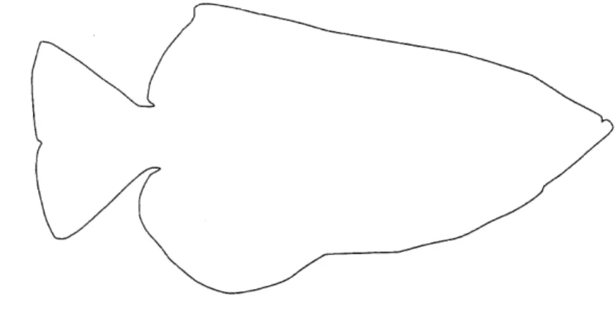
In order to obtain a baseline of the shape of an archerfish with the intent of measuring its thrust production, the most important view is its profile in order to have the outline of the fins. The image needed to be of an archerfish view from the side with a light background so that the fins would contrast well with it. I found such an image of this view from the San Diego zoo.
4,
C*1-Figure 3-1: Adequate Baseline Picture of an Archerfish [7]
From there, the image needed to be processed into a CAD model. The fist step I took was to trace the outline in the profile in Inkscape and saved as a DXF to export to Solidworks. Vector graphics were selected over bitmap in order to scale without loss of resolution.
Figure 3-2: Body trace of an archerfish
Within Solidworks, the body profile was lofted, without the fins, using 10 elliptical sketches. The archerfish average standard length is 93.5 1.9mm [29]. Because of
the inner volume required for actuators and other component the robot needed to be larger. However it was restricted in size by the dimensions of the 3D printers available. Since any effect on thrust produced by the fins would probably scale with size, it was decided to maximize the length. This ended giving an approximate standard length of 400mm to the model. In [20], a table is given for the size of five Toxotes microlepis. From it the following average non dimensional factors were obtained. At this point, it was decided that two variants of the fish would be modeled. The first would be a slim variant with approximately half the W/L ratio. This variant would have a lower second moment of inertia around its y-axis making it bend more easily which would show larger body length waves for analysis. The second would be the average variant.
Table 3.1: Non-dimensional size factor of archerfishes W/L H/L
Figure 3-3: Lofted body of a slim archerfish model
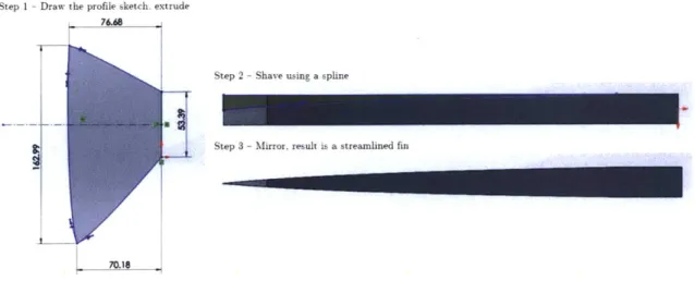
The next step is to model the fins separately. The archerfish has 3 propulsion fins: a dorsal, a caudal, and an anal fin. In order to model them, their profiles were traced closing the sketches where they meet with the body, then extruded by 5mm. This gave a block object that needed to be shaved into their final dimensions. The extrude cut sketches are triangles with a spline replacing the hypotenuse. The extrude cut is mirrored in the final step to give a streamlined fin. Fins could require a repeat of step 2 and 3 depending of their geometry. The dorsal fin had an extra step where the mating surface with the body was scribed using the "combine" feature. This was done for a better fit, but is optional if you are willing to use more adhesives.
- Draw the profile sketch, extrude 76.68
Step 2 -Shave using a spline
Step 3 - Mirror. result is a streamlined fin
70.18
Figure 3-4: Fin modeling process
Following this process and ready to be modified
for all three fins, the starting body of the fish was modeled to accept its components.
Figure 3-5: Starting body of the Slim Archerbot
3.1.2
Component selection
As shown in [30] and [1], fish motion can be replicated best if the body is segmented to replicate the flexing of the spine. Therefore, its was decided that the Archerbot would have at least one spinal pivot point. The caudal and anal fin also needed to be actuated. It was decided to have the dorsal fin passive. That meant a minimum of
3 actuators. First rotary servo motors were investigated because of they were used
for the Robotuna. They would be able to provide ample of torque, but they were
expensive when compared to the alternative option, stepper motors. Servo motors are normally used for high speed high torque application. The movement of a fish does not need to be actuated by a motor than can do 2000 RPM. Stepper motors are readily available, cheap and they have a high holding torque which would be useful if testing requires to hold the fin stiff. Steppers were selected as actuators.
Figure 3-6: The four size of tested steppers
The steppers needed to be strong enough, not generate so much heat as they would reach the glass point of the surrounding plastic, and slim enough to fit within the body of the fish. Four sizes were considered: NEMA17, 14, 11, and 8. NEMA17 are the most available and powerful of the group. They were selected for the average variant, but could not fit in the slim version of the Archerbot. NEMA14 motors would fit, but could not be distributed inside the model and would have to be cramped in the thickest part of the fish. NEMA8 and 11 were able to fit everywhere. During testing however, the NEMA8 would become so hot that they could not be touched for more that a few seconds without pain while the NEMA 11 remained only slightly warm.
A4988+
0 0
0 0
RE: I o 1
ARDUINO
Figure 3-7: Wiring diagram for the stepper drivers
The control board selected is a Arduino Mega 2560, but any Arduino board with at least 2pin per motor would work. The coding environment is Arduino IDE with the "accelstepper" and "multistepper" libraries by Mike McCauley [311 added to the sketches.
3.1.3
Body modifications
Once the components were selected, the process of inserting them into the fish body could start. The fish was split in two parts, a head that would be printed rigid and the rest of the body that would be printed with flexible filament. The body was made into a shell to accept the actuators and the head was pierced to allow the components wiring to exit the Archerbot. The fin actuators had to be mounted to the skin, so they were made to conform to the shell and holes that could accept M3 screws were added. The spine actuator was added at the body midpoint and its mount is attached to the head. The movement transmission units for the fins take their design inspiration from [2] where a set of bevel gear is used to change the plane of rotation of the motors. Cutouts were added to the fins to allow for actuation. A section view of the modified Slim fish can be seen in figure 3-8.
Figure 3-8: Section view of the Archerbot
As can be seen, there is some remaining space available that would allow to expand on the design to either add more actuators or integrate sensors, power, or structural elements to this prototype. To view each part in more details, see appendix A.
The average variant was modeled using the same method, but practice made the resulting profile more accurate.
Chapter 4
Fabrication
4.1
Additive Manufacturing
Most of the components were made using Fused Deposition Modeling (FDM) construc-tion. The slicer software used was Ultimaker Cura. The printer used was a Creality CR-10 with the following modifications:
" Updated Marlin firmware
[32]
* Frame brace by Josh Tenny (RebelRousingProps) [33]
" Flexion Extruder with adapter brackets by Bratan K [34]
* E3D All-metal v6 HotEnd * Titanium heatbreak
" Vibration dampers for the X and Y axis
* Mirror baseplate
" Added heat bed insulation
The filaments used were:
* NinjaFlex White TPU
* Amazon premium white PLA * Hatchbox grey PLA
4.1.1
Bed Type
One of the main challenge of FDM printing is to get the part to stick to the printing bed for the entire length of the print. The critical point of this challenge is the first layer as if it is not laid properly, it can lead to the immediate failure of the print or worse a failure mid-print which waste more material and time. To tackle this problem, many build surfaces exist. A build surface is what you put on the print bed as an intermediate between the bed and the nozzle. There is many materials and coating to consider and as the technology evolves many group come up with their own solution to tackle their particular problem. For this thesis aimed at creating bio-inspired robots, some parts are sliced then glued. This led to the requirements that mating surfaces needed to be relatively smooth to get good adhesion. Four build surfaces were investigated along with two coatings. Flexible textured plate such as the one manufactured by BuildTakTMprovided very strong adhesion. Nevertheless, the first layer finish was coarse and it was very hard to remove flexible prints without breaking them. A common solution for bed adhesion is to put painter tape on a flat bed plate. It gave good results and the surface finish was not as rough as for the textured plate, but a lot of time was necessary to replace the tape that would be damaged between prints. The printer used came with a glass plate and results were good giving a very flat and texture-less surface. The problem was that the 300x300mm plate was not completely flat leading to problems with large print. To correct that problem, a mirror plate was used as a substitute. Mirrors have to be very flat to keep their optical properties which makes them very good as a build plate. Two coatings were tried to improve bed adhesion with PLA and flexibles. They are Polyvinyl Acetate (PVA) based glue and hairspray. Both helped for small prints but hindered large one. One hypothesis is that on large prints, the adhesives have time to dry before the end on
the first layer which lead to a surface that filaments don't adhere to. Both coatings also have to be cleaned on a regular interval leading to more human involvement. The solution that gave the best surface finish, an acceptable success rate for both large and small print, and the best quality of life factors was the bare mirror. Once properly washed in soapy water, it took about one month before it needed to be washed again
because of contaminant that would settle on its surface.
4.1.2
Truing
Also called "levelling" by many, bed truing is a critical step to achieve success. Truing is done with reference to the nozzle and a distance of 0.1mm for a 0.4mm nozzle is normally aimed for to achieve best results. Many features exist to make this step easier on the operator such as probes that automate the process of a four corner truing or software compensation using grid mesh. For this project, the printer only had manual truing available and a standard office printer paper sheet was used as a feeler gauge to ensure proper distance between the bed and the nozzle. Truing is done to achieve even, not distorted, first layers. It is essential to get good bed adhesion and if a part does not stick, truing the bed again often solves the problem.
The distance between the nozzle and the bed will dictate how much "squish" the extruded filament will be under. Squish can be described as how much the melted filament spread under the force of the nozzle and the extrusion as it is coming out.
Some amount of it is desired to achieve good adhesion, but too much leads to initial layer failure or "elephant footing" a problem where the first few layers are larger on the x-y plane leading to improper dimensions of the base. Squish became really important when printing large flexible parts like the ArcherBot back shells. A normal amount of squish would leed to a good first layer, but because of the size of the part would not prevent warping.
Warping is a common problem in slender parts where the contraction caused by the part cooling leads to a failure of adhesion. The part curls up and rips itself from the bed.
Figure 4-1: Slim Archer shell warping under tension due to cooling
4.2
Operations
During this project, operational availability was limited by the required upgrades in the beginning, and maintenance and repairs throughout the year this study took place. The printer ran almost every day with minimal break and had several single jobs that lasted over 24hrs of continual running. Wear was localized in:
e Cable connections (thermocouple probe broke 4 times, nozzle fan de-soldered
once)
* Nozzle clogs had to be resolved over 10 times * Heatbreak had to be changed once
* Extruder assembly had to be overhauled twice
Rate of success was highly dependent on the part geometries. For similar future project, it would be interesting to see a printing log listing part name, part weight, presence of support, and statement of success. This would help quantify to process and develop a cost model for it.
The print settings used were the following for both PLA and flexibles. Table 4.1: Common print settings for both type of filament
Nozzle Size [mm] 0.4
Layer Height [mm] 0.2
Wall Count 2
Top Layer 3
Bottom Layer 2
Layer Pattern Concentric
Infill [%] 15
Infill Pattern Cubic
Printing Temperature [degC] 205
Bed Temperature [degC] 60
Acceleration [mm/s2] 500
Jerk [mm/s3] 20
Support Depend on part
Support Pattern Grid or Lines
Support Ovehang Angle [deg] 50
Build Plate Adhesion Skirt or None
Where it differed was the print speed. Flexible had to be printed at 30mm/s while PLA could be printed at 60mm/s. Printing with flexible material is different than printing with hard material especially if it is also very stretchable. The difficulties start at the extruder where the filament need to be very well supported since we are essentially pushing rope. The first modification that was required to achieve success was to convert the Boden style extruder of the printer to a direct extruder by placing the extruder motor on the x-axis carriage. This had for effect to greatly reduce the distance between the motor and the nozzle, but increased the mass of the carriage greatly. At the time, this solution was the only one available, but at the Midwest RepRap Festival 2019, Zesty Technologies presented a conversion kit using a flex shaft which allows for all the benefits of direct drives without the drawback of a heavier
carriage. This method should be tested in future work.
There was two main type of flexible part: the fins and the shells. Three techniques were investigated for fin printing. The first one prints the fin from a flat surface and would be the method used for printing the fin in hard material if it was necessary to print in one piece. This method did not work since the nozzle applies sideways forces
of the print and as the part becomes taller, it starts to wobble a lot. The second was to float the fins over a support lattice. This method worked in printing the fin in one piece, but one side had to undergo major post-processing and the fin was more pliable on one of its two side. The third method, the one ultimately chosen, was to split the fin along its sagittal plane and printing it in two parts from the large flat surface generated by the cut then combining them with cyanoacrylate based adhesive.
Method I Method 2 Method 3
Figure 4-2: The trialed methods of printing fins
In order to print the back shells, a similar method to the fins is utilized. There is no intuitive orientation that could be used, therefore the shell is split in two and printed for the flat surface created by the cut. At that cut, interior facing flange are added to increase the contact area to the build plate and for post-processing adhesion. The shells is printed using a lot of support because of the interior void. The support pattern for the shells is the grid. Otherwise, the support is too flimsy and upper layers fail with a line pattern.
Figure 4-3: Back shell mid-print
4.3
Assembly
The first step is to print all the required parts. Detailed bill of materials are included in Appendix A. Then, the following sequence can be followed:
1. Waterproof the stepper motors
2. Assemble the motion units (test)
3. Fastened the units to one half shell
4. Affix the head on the same half
5. Wire the motors
7. Affix the head to the second shell
8. Close the shell
9. Install levers and gears 10. Install fins (test) 11. Waterproof exterior
12. Inspect
4.3.1
Waterproofing Stepper Motors
Bearings
Shaft
Top
Plate
Bod
Core
Bottom Plate
Figure 4-4: Parts of the NEMA11 motors
Stepper motors are made of multiple parts. Any interface and perforation potentially allows for water ingress. The robots themselves are waterproofed, but in the case of a leak, it was decided to mitigate that risk by adding another waterproofing layer. As can be seen on the image below, there is four main ingress points.
face
Top Hole
Tp
Inter
Bottom
I
Bottom Hole
Figure 4-5: The four main water ingress points of NEMA 1
The bottom hole was the easiest point to plug. A single flexible plate could be glued to the bottom of the motor using a continuous circular glue line. This effectively sealed that point. The other points required more testing. The bottom and top interface can be grouped as they offered the same challenges. Gaskets were manufactured to seal that interface, but modifying the internal volume of the motors kept them from turning properly. Three gasket configuration were tried: both, top only, and bottom only. All configurations prevented the motors to turn satisfactorily. The mating surfaces of the interfaces is machined aluminium, therefore the risk of ingress is low, but to diminish the risk further, since gaskets could not be used, a thin layer of marine grease was applied. This did not prevent the motors from turning and should help repel water from coming through the interfaces. The top hole had to be plugged too, but because of the shaft, the solution had to be different than the one for the bottom hole. The solution investigated was a flanged flexible sleeve plug. There is two possible insertion point for the plug: top or bottom of the NEMA11 top plate. The
dimensions were varied and both insertion points were tried. The motors were tested between each iteration. Insertion from the bottom could produced desired result, but the dimension of a plug could work for one motor and prevent turning on the next. This made a standard solution impossible. On the other hand insertion from the top had a universal success rate. The plug inner bore needs to be tight enough to grip on the shaft and its outer diameter small enough not to create interference with the top plate. The flange needs to be wide enough to cover the remaining of the hole. A layer of marine grease is added on top of the plug for increased protection.
Figure 4-6: Waterproofed Motor
4.3.2
Assembling the motion units
A motion unit is defined as a sub-assembly that incorporate the actuators (stepper
motors) in the design. They are composed of the following main parts categories:
1. Actuator
2. Gasket
3. Mount
4. Coupling
6. Bearing
7. Gears
8. Lever
The actuator is fastened to the mount using the standardized NEMA layout. A gasket is sandwiched between the mount ant the actuator. This gasket has two purpose. The first is to prevent water that would enter through the shaft piercing from finding its way into the shell cavity. The second purpose is to help align the motor shaft within the mount. The shaft extension is inserted in the coupling. to make the coupling match the shafts of the motor and extension, two methods are utilized. The first use the thermal characteristics of the two different material that compose the parts. The shaft is heated with a soldering iron a inserted in the coupling. The plastic of the coupling melts around the shaft creating a perfect fit. The second method is to pound the shaft in with a hammer. Although the second method does not produce as good as a result as the first, it is less likely to fail. During the melting process, it is very difficult to keep the shaft at the right temperature and prevent it from opening the bore too much via sideways motion. The impact method is therefore the recommended method for early prototype. Once the shaft extension is in the coupling, it is long enough to reach the motor shaft within the mount and be fitted there. The shaft fitting process and the flatness of the mount interface with make it so that the coupling will not be perfectly concentric within the mount. It is not as big as a flaw in this case because the motor will never complete full rotations, but concentricity can almost be completely restored using the compliance of the gasket.
By increasing or decreasing the tension on the mounting fasteners one by one, the
mount can be moved in relation to the motor shaft to provide satisfactory alignment. Once that is done, the bearing, gears, and lever and be installed temporarily to test the actuation of the unit. A test should be performed to verify proper functioning at this point because the next logical testing point is after the shell is closed and then the units can only be retrieved by destroying the shell.
Figure 4-7: Assembled Motion Units Ready for Testing
4.3.3
Fastening the units to the shell
Once testing is completed and successful, the gears, and lever can be removed. The motion units are attached to the shell using standard fasteners that screw in the mount. The threads on the mount have to be tapped first. Enough tension should be placed on the fasteners to locally deform the shells.
4.3.4
Affixing the head
When printing the shells as described above, the collar designed on the shell to mate with the head does not have a fine surface finish. For this reason a high volume of adhesive needs to be used to fill all the gaps. Hot glue was a good solution for this project. It is inexpensive, readily available, retains a high viscosity even in its fluid state, and fills gaps efficiently. Using a dot of cyanoacrylate based glue to tack the head to the shell in the wanted position then laying a heavy bead of hot glue as the main adhesive was the process that produced the best results.
4.3.5
Wiring the motors
Stepper motors have short wiring that may be enough if the prototypes were fully enclosed, but because the ones that were designed are tethered, extension had to be made. The selected standard is the Dupont connectors because of availability and compatibility with breadboards. To make the extensions, you will need a crimping tool, wiring, Dupont tabs, and Dupont housings. Cable combs were useful to keep the
16 wires coming out of the fish to become a mess. Once the extensions are complete,
they can be routed through the designed channel in the head to the shell cavity. Once connected, it is important to have a method of identifying which cable connects to which motors from the outside of the robot as the inside will become unavailable.
Figure 4-8: Archerbot with Motors Wired
4.3.6
Closing the shell
To close the shell, the first step is to fasten the motion units to the second shell this aligns both shells together. Then, the perimeter is sealed using hot glue at the head
and cyanoacrylate glue elsewhere. A continuous seal should be made around the shaft piercing. Once the shell is closed, all the seams are inspected in order to find gaps. If some are found, they can be eliminated with more adhesive.
4.3.7
Finishing
With the shell closed, the gears and the lever can be installed and permanently glued in place. The fins are mounted with fasteners which allows them to be changed if different profiles or materials need to be tested. The dorsal fin is glued in place. A final inspection is then given to the whole assembly to determine if any water ingress points were forgotten. Once all that is done, the robot is ready to go in the water.
Chapter 5
Results
This thesis aimed at creating biomimetic robots for experiments using additive man-ufacturing techniques. To direct the design, it was decided to start with the shape of the archerfish as baseline. The foils needed to be independently actuated and removable because the research intent was to find if there exist an interaction between the anal and caudal fin. Are their thrust vector merely additive or is there more to the archerfish propulsion. A special care was given to maintain costs low. This is because, with the help of rapid prototyping, this work could be replicated to recreate many piscine forms or other underwater robots for increase research in this domain without the need for big budgets.
5.1
Applying the process to other designs
To evaluate the rapidness of the design process, a turtle robot like the one in [8] was recreated. The robot has four flapping and tilting fins and can be seen in figure
5-1. The presence of two symmetry planes did accelerate the CAD process, but from
reading the paper to finishing the model by carving the cable channels a total of only
6 hours was required. This is compared to more than 80 hours for the slim variant
Figure 5-1: CAD model of a robotic turtle using the design of [8]
This robot could also be used to measure the interaction of flexible flapping foils. Since the type of oscillation is different from the archerfish propulsion, results should be compared to identify if effects appear in one or both of the robots.
The design process is not limited to biomimetic research. Specialized robots can be developed quickly and at reasonable costs. When designing the Archerbot it was desired to measure interaction between anal and caudal fin, but when looking at the profile of the fish, we can see that the fin overlap is not maximal. The overlap is highlighted in purple in figure 5-2.
Figure 5-2: In-Line Fin Overlap for the archerfish
To measure the interaction, the design does not need to be inspired by a living creature. Instead, something more traditional can be conceptualized such as the model seen in figure 5-3.
Figure 5-3: Non-biomimetic robot for foil on foil interaction
1. The foils have a 100% overlap
2. They do not count on body oscillation to produce sway, each foil has a dedicated sway motor
3. The distance between foils can be adjusted by changing the length of the
extension rods linking the two sub-assemblies
4. There is no flexible shell required. This mean that fabrication should be easier
5. The motors have a larger range of motion
5.2
Cost
To determine the cost of a prototype, the values of table 5.1 were used.
Table 5.1: Initial cost data
PLA [$/g] 0.025
Ninjaflex TPU [$/g] 0.085
eSun TPU [$/g] 0.04
Electricity [$/kWh] 0.2782
3DP Average Power Draw [kW] 0.142 3DP Time Cost [$/h] 0.03950
The cost of electricity is from my March 2019 bill from Eversource and includes supply and delivery charges. This price intensity will be largely driven by where the printer is situated on the globe and the type of customer. The average power draw is a calculation from the energy used by a 12 hour print as measured by a socket type meter (P3 P4400 Kill A Watt Electricity Usage Monitor). The temperature settings used to obtain that average are 205 degC for the nozzle and 60 degC for the bed.
The complete BOM of the average variant was used for the cost analysis and results can be seen in table 5.2.

![Figure 2-2: CAD Model of a Knifefish like robot [2]](https://thumb-eu.123doks.com/thumbv2/123doknet/14687633.560510/20.917.180.791.215.838/figure-cad-model-of-a-knifefish-like-robot.webp)

![Figure 2-5: Laying KT,,hip curve on a open water diagram from [4]](https://thumb-eu.123doks.com/thumbv2/123doknet/14687633.560510/26.917.127.789.185.860/figure-laying-kt-hip-curve-open-water-diagram.webp)
![Figure 2-6: Velocity and Force diagram for a particular radial position on a lifting line [5]](https://thumb-eu.123doks.com/thumbv2/123doknet/14687633.560510/27.917.150.758.127.505/figure-velocity-force-diagram-particular-radial-position-lifting.webp)
![Figure 2-7: Wdrtsild Pre-swirl Stator Concept [6]](https://thumb-eu.123doks.com/thumbv2/123doknet/14687633.560510/29.917.120.780.395.876/figure-wdrtsild-pre-swirl-stator-concept.webp)
![Figure 3-1: Adequate Baseline Picture of an Archerfish [7]](https://thumb-eu.123doks.com/thumbv2/123doknet/14687633.560510/33.917.125.778.348.836/figure-adequate-baseline-picture-archerfish.webp)