HAL Id: hal-02377106
https://hal.archives-ouvertes.fr/hal-02377106
Submitted on 22 Nov 2019
HAL is a multi-disciplinary open access
archive for the deposit and dissemination of
sci-entific research documents, whether they are
pub-lished or not. The documents may come from
teaching and research institutions in France or
abroad, or from public or private research centers.
L’archive ouverte pluridisciplinaire HAL, est
destinée au dépôt et à la diffusion de documents
scientifiques de niveau recherche, publiés ou non,
émanant des établissements d’enseignement et de
recherche français ou étrangers, des laboratoires
publics ou privés.
Endoscopy: Preclinical Application to ESD
Lucile Zorn, Florent Nageotte, Philippe Zanne, Andras Legner, Bernard
Dallemagne, Jacques Marescaux, Michel de Mathelin
To cite this version:
Lucile Zorn, Florent Nageotte, Philippe Zanne, Andras Legner, Bernard Dallemagne, et al.. A Novel
Telemanipulated Robotic Assistant for Surgical Endoscopy: Preclinical Application to ESD. IEEE
Transactions on Biomedical Engineering, Institute of Electrical and Electronics Engineers, 2018, 65
(4), pp.797-808. �10.1109/TBME.2017.2720739�. �hal-02377106�
1
A Novel Telemanipulated Robotic Assistant for
Surgical Endoscopy: Preclinical Application to ESD
Lucile Zorn
1, Florent Nageotte
1Member, IEEE, Philippe Zanne
1, Andras Legner
2, Bernard Dallemagne
3, Jacques
Marescaux
2,3and Michel de Mathelin
1, Senior Member, IEEE
Abstract—Objective: Minimally invasive surgical interventions in the gastrointestinal tract, such as Endoscopic Submucosal Dissection (ESD), are very difficult for surgeons when performed with standard flexible endoscopes. Robotic flexible systems have been identified as a solution to improve manipulation. However, only a few such systems have been brought to preclinical trials as of now. As a result, novel robotic tools are required.
Methods: We developed a telemanipulated robotic device, called STRAS, which aims to assist surgeons during intraluminal surgical endoscopy. This is a modular system, based on a flexible endoscope and flexible instruments, which provides 10 degrees of freedom (DoFs). The modularity allows to easily set up the robot and to navigate towards the operating area. The robot can then be teleoperated using master interfaces specifically designed to intuitively control all available DoFs. STRAS capabilities have been tested in laboratory conditions and during preclinical experiments.
Results: We report twelve colorectal ESDs performed in pigs, in which large lesions were successfully removed. Dissection speeds are compared with those obtained in similar conditions with the manual AnubiscopeTM platform from Karl Storz. We
show significant improvements (p = 0.01).
Conclusion: These experiments show that STRAS (v2) provides sufficient DoFs, workspace and force to perform ESD, that it allows a single surgeon to perform all the surgical tasks and that performances are improved with respect to manual systems.
Significance: The concepts developed for STRAS are validated and could bring new tools for surgeons to improve comfort, ease and performances for intraluminal surgical endoscopy.
Index Terms—Medical robotics, Intraluminal surgery, Teleop-eration, Endoscopic Submucosal Dissection
I. INTRODUCTION
I
NTRALUMINAL surgical procedures have been continu-ously developed over the last 30 years. These interventions are generally performed using flexible endoscopes originally designed for diagnosis. These endoscopes do not allow for the bimanual and angled use of two surgical instruments. As a consequence, complex procedures such as EMR (Endoscopic Mucosal Resection) or ESD (Endoscopic Submucosal Dissec-tion) are difficult to perform.Many mechanical platforms have been proposed to handle these problems and to make surgery easier [1] (EndoSAMURAITM[2], Direct Drive Endoscopic System [3],
Contact : Nageotte@unistra.fr. Authors are working with
1 ICube (UMR UDS-CNRS 7357), Strasbourg University, France. 2 IHU-Strasbourg, Institute for Image-Guided Surgery, Strasbourg, France. 3 IRCAD, Research Institute against Cancer of the Digestive System,
Strasbourg, France.
Copyright (c) 2016 IEEE. Personal use of this material is permitted. However, permission to use this material for any other purposes must be obtained from the IEEE by sending an email to pubs-permissions@ieee.org.
Incisionless Operating Platform [4], AnubiscopeTM[5]). These platforms augment and improve the possibilities at the distal end. For instance, the AnubiscopeTM platform provides better stability, triangulation, multiple channels and instruments with distal bending [6]. However, these platforms require the co-operation of at least two skilled persons, sharing a limited workspace and working in tiring positions. This does not support a widespread acceptance and use of such surgical techniques.
This is why intraluminal surgery, as well as transluminal surgery and single port laparoscopic surgery, could signifi-cantly benefit from robotic developments [7].
Two approaches have been put forward to help surgeons and endoscopists in intraluminal surgery:
• Robotic endoscopes and guides such as the Medrobotics Flex R [8], the i-Snake R from the Imperial College [9],
or motorized endoscopes from the University of Twente [10], which make the positioning and the use of standard instruments inserted inside the guide easier for surgeons. • Complete robotic telemanipulated platforms with specific
motorized instruments.
This second approach is similar to the concept of robotics applied to laparoscopic surgery [7]. Depending on the location of the surgical site, different structures have been proposed, which can use rigid or flexible tubes in combination with rigid discrete joints or continuous steerable sections. Treatments close to the natural orifices, in the rectum and the upper esophagus can be achieved with totally or partly rigid guides, as it is the case with the IREP robotic system [11]. However, for more distant targets, the main shaft should be flexible so as to conform to the patient’s anatomy during the initial navigation stage towards the surgical site.
To operate up to the sigmoid colon, a flexible base of at least 30 cm long is required and, consequently, platforms mainly intended for laparoscopic or single port surgery (Transenterix SurgibotTM[12], Virtual incision [13], Titan Medical SportTM [14] or SPRINT [15]) cannot be used. In this field of in-traluminal surgery, only a few robotic platforms have been proposed so far. Three complete teleoperated systems can be mentioned. (1) ViaCath was originally developed by Endovia and it was used in in vivo experiments [16]. However, users deemed telemanipulation difficult [17]. ViaCath was bought by Hansen Medical. However, it is no longer available. (2) MAS-TER is a robotic system based on a standard double-channel gastroscope, which was developed by Nanyang Technological University [18]. It has reached the level of clinical trials, but several limitations, such as the necessity to have assistants to
manipulate the endoscope have been mentioned [1]. (3) The robotic system developed by the university of Twente in the Teleflex project [19] is based on a standard flexible endoscope and articulated instruments manufactured by Karl Storz. No in vivo trials of the complete telemanipulated system have been reported yet. One can also mention a patent application for a miniature robotic device, which could be adapted to flexible endoscopes [20]. However, no actual system has been presented yet.
Our goal was to develop a modular robotic system, which could be easily set up for intraluminal surgery, which would rely on most assets of conventional endoscopic systems, and which could provide simple and intuitive control for the user. A first version of STRAS (v1) was presented in [21] and [22] and the modular architecture is patent pending [23]. After ex vivo tests with this initial version, we have devel-oped a novel version (v2), which brought solutions to the observed limitations. This article addresses the challenges of intraluminal surgery through the following contributions: 1) The description of the design, features and functionalities of STRAS v2, with an emphasis on the novelties with respect to the previous design. 2) The report of in vivo ESD showing the feasibility of the use of the robot. 3) The comparison of in vivoresults with those obtained with manual systems, demon-strating the improved dissection speed and 4) a comparison with other existing devices and discussions on advantages and limitations.
The paper is organized as follows. Section II briefly presents the AnubiscopeTM platform and the concept of the robotic system. Section III describes the mechatronic components of the STRAS v2 slave part and provides quantitative features of this system. Section IV presents the specific master interfaces with usability tests results. Section V outlines the typical workflow of the robotic system use for intraluminal surgery. Section VI reports twelve preclinical trials where ESDs are simulated in the rectum of an animal model. The article ends with a discussion on the results, limitations and assets of the current system.
II. ROBOT DESIGN AND CONCEPT
A. Modified AnubiscopeTMplatform
STRAS is a robotic system based on a modified shortened version of the manual AnubiscopeTM platform developed by Karl Storz (Tuttlingen, Germany). The AnubiscopeTMplatform is a CE-marked, totally flexible system initially developed for Natural Orifice Transluminal Endoscopic Surgery (NOTES). It consists of a main endoscope and of two articulated instru-ments (see Fig. 1).
Main endoscope: The main endoscope is equipped with a camera at the distal tip, a lighting system, and a channel for fluids (air for insufflation, suction to remove smoke, water to cleanse the camera). The distal part of the endoscope can be deflected along two orthogonal directions. It is actuated by two pairs of antagonist tendons. The passive shaft is 350 mm long, the steerable distal part is 185 mm long, and the backbone consists of 14 vertebras. It is very similar to a standard endoscope, except for the larger diameter (16 mm), which
bending
translation
rotation
rotation
deflections
translation
β θz main endoscope camera lighting grasper bending instruments hook γ inner channel insufflation lateral channels tz shellFig. 1: Distal part of the endoscopic platform (manual AnubiscopeTM and robotic STRAS) with the available DoFs.
allows to house three working channels for instruments. One channel is located at the core of the scope’s shaft (diameter: 3.2 mm), while two lateral channels (diameter: 4.3 mm) are located inside, but at the edges of the shaft, and terminate in a mobile shell. This shell can be opened and allow to deviate the instruments from the main direction of the endoscope.
Instruments: The AnubiscopeTMplatform has specialized instruments with long flexible shafts (length: 900 mm) and a short bending distal part (length: 18.3 mm, diameter: 3.5 mm) consisting of 11 mobile vertebras. A pair of antagonistic tendons provides bending of the distal part in one plane. The instruments are hollow and can receive inserts equipped with distal effectors, either mechanical (graspers) or electrical (knife, hook to perform electrosurgery). The insert can be attached to the instrument by screwing it to the distal tip of the shaft. These instruments can be inserted into the lateral channels of the endoscope.
Overall, the AnubiscopeTM platform has 10 degrees of freedom (DoFs)1 (plus graspers opening / closing motions) (see Fig. 1).
B. The robot concept
The AnubiscopeTM platform requires a good cooperation between at least two persons who share a restricted workspace around the endoscope handle. In this context, robotization and telemanipulation can provide many advantages, such as the possibility for a single user to control all DoFs, better comfort of use or motion scaling. The conceptual idea for STRAS was to design a teleoperated modular platform, which could be easily set up at the side of the operating table. It was decided to keep most of the original design of the AnubiscopeTM platform. The insertion of the endoscope inside the lumen is kept manual for safety reasons. Only the surgical part of the procedure is teleoperated, which represents the most difficult and longest stage of the whole procedure.
a. Endoscope
b. Instruments modules
c. One Rotation/Translation module e. Cart
f. Rotation and translation drives of the cradle g. Remote controller Cart c g d f e cradletranslation cart EA cart H cradle rotation
d. Cradle (U-shaped arm) a
b
Fig. 2: General view of the slave system and DoFs of the cradle and cart.
III. MECHATRONIC ARCHITECTURE OFSTRASV2 STRAS v2 is the evolution of a first prototype described in [21], which was tested in the laboratory ([21], [22]) and in ex-vivomodels. The general modular architecture of the slave system was validated. However, according to the feedback provided by surgeons, several important changes have been made regarding the design of the system. Here, we present an overview of the new system.
A. Slave system architecture
Functionalities have been separated into elementary parts called modules (see Fig. 2 for labels), which are all meant to be reusable.
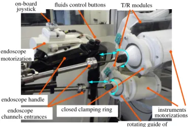
The complete robotic system consists of one endoscope module (a), of two instrument modules (b), of two modules called ”Translation / Rotation Modules” (T/RM) (c), of one cradle (d) and of one mobile cart (e), which supports all other modules. For complex surgical procedures, additional instru-ment modules can be used to replace the original instruinstru-ment modules, for instance to provide other medical effectors. The cart, cradle and T/RM modules can be easily assembled at the beginning of the surgical procedure to set up the slave robot. a) Endoscope module: The endoscope module comprises the endoscope and the motorization of its two deflections αx and αy. Two motors with gears replace the manual wheels and drive two pairs of tendons (see Fig. 4). The actuation is placed in a casing fixed to the endoscope’s handle. Space has been optimized in the motor housing to make it small (dimensions are 150 mm × 95 mm × 50 mm), light and easy to manipulate. An on-board mini joystick is attached to the motor housing and allows the user to control the deflections of the endoscope during the manipulation of the endoscope’s handle, as will be described later.
b) Instrument modules: The instrument modules include a flexible instrument and motorization for its bending (defined by angle β, see Fig. 1) and grasper opening / closing (angle
d e a c instrument module cm f. Pulley-belt transmission e. Push-pull grasper rod d. Rotation drive c. Translation drive
b. Steering wires for instrument bending a. Closing ring of T/RM + rotation guide
T/RM translation
rotation
f
b
Fig. 3: Close view of one instrument module set up inside a T/R module.
γ between jaws). The manual handle has been replaced by a cylindrical casing with a conical nose, which includes the actuation means (see Fig. 3). The cylindrical part is 145 mm long and 92 mm in diameter. The proximal extremity of each steering wire is attached to a carriage; both carriages can be freely secured on a toothed belt, on opposite strands. This toothed belt runs between one free pulley and one actuated pulley, which is driven by a motor through a gearbox with angle transmission. With this mechanism, it is possible and simple to tune the tension of the steering wires. With increased cable tension, the dead-zone at the center of the deflection range and the backlash (see Section III-B) tend to decrease, hence providing better control of the bending to the surgeon. For mechanical instruments, the push-pull rod for grasper opening / closing is clamped between two planar surfaces of a carriage. This carriage is driven similarly to the ones which control tendons.
Electrical instruments are fitted with an electric connection for high-frequency electrosurgery, going out of the module at the proximal end.
A ball bearing is mounted close to the nose and serves to guide module rotation.
The flexible shaft of the instrument is attached at the distal end of the motor housing by means of a cable gland, while the steering wires run inside the housing and are attached to the toothed belt. The shaft can be easily detached from the motor housing using a screwdriver only. This allows the instrument shaft to be changed between medical procedures if needed.
c) Translation / Rotation modules: Translation and Rota-tion Modules (T/RM) are used for the translaRota-tion and rotaRota-tion of the instrument modules with respect to the endoscope. They can be mounted onto a support attached to the cradle (see next paragraph), at the proximal side of the endoscope module (see Fig. 4). T/RMs have an L-shape: the longest bar is 200 mm long, 90 mm wide, parallel to the translation and rotation axes and contains the drive and transmission (pulley, belt) of the translation movement; the other bar is located at the
closed clamping ring T/R modules joystick on-board endoscope endoscope motorization endoscope handle channels entrances rotating guide of instruments (ball bearings)
instruments motorizations fluids control buttons
Fig. 4: View of the instrument modules, T/RM and endoscope module when the system has been set up.
proximal end of the instrument and contains the transmission for rotation. An instrument module can be simply and quickly inserted inside a T/RM by (see Fig. 5): 1) opening the ring located at the distal end of the T/RM, 2) inserting the flexible shaft of the instrument inside the channel of the endoscope, 3) installing the motor housing of the instrument module on the T/RM (its orientation is defined by mistake-proofing locating pins in the proximal side of the T/R module), 4) closing the ring at the front end using a quick fixation screw. When closed, the ring clamps the ball bearing located on the instrument module, which allows to guide the rotation of the module.
d) Cradle: The cradle allows to hold the endoscope and the T/R modules together and to provide them with rotation and translation along the axis of the endoscope at its proximal side (see Fig. 2 and 4). The cradle consists of a shallow U-shaped aluminum arm mounted at its proximal end onto the output shaft of an angle transmission gearbox. The rotation means can be translated by a ball screw linear transmission. The endoscope can be attached at the front end of the U-shaped arm in a fixed orientation using a mistake-proofing clamping system. Both T/R modules are attached at the proximal end of the U-shaped arm in a fixed orientation, which ensures the alignment of the axis of the instrument modules along the entrances of the lateral channels of the endoscope (see Fig. 4).
e) Cart: The cart is a mobile platform, which can carry all other modules and allows for free manual positioning and orientation of the whole system in a horizontal plane (see Fig. 2). The height (H ∈ [800 mm, 1400 mm]) of the cradle (defined at its back with respect to the floor) and its elevation angle with respect to the horizontal plane (EA ∈ [−30o, +30o]) can be adjusted in large ranges thanks to two linear electric cylinders. The user can control them with a wired remote controller, allowing for different surgical access points, including the upper and lower GI tracts as well as single port laparoscopic surgery.
Once the endoscope module and instrument modules have been mounted onto the cradle (see Fig. 2), all 10 DoFs (+grasper) of the AnubiscopeTM platform are motorized and
quick fixation screw mistake−proofing pins
opened clamping ring
entrance endoscope channel
Fig. 5: Close view of the right T/R module before the instrument module installation.
can be teleoperated. B. Features of STRAS v2
All elements of actuation (motors, gears, end-stops) have been chosen in order to provide a robotic system with similar capabilities as the manual AnubiscopeTM platform.
The actual workspace and kinematic features of the slave robot have been assessed in the laboratory using an external measurement system composed of two AVT Prosilica GC660 cameras equipped with F1.8/6.5-52 mm objectives. Applicable forces were also measured using the setup shown in Fig. 8. These features were measured for different configurations of the endoscope: straight, slightly deflected (αx = 30o) and more strongly deflected (αx = 60o). No significant effects were observed on the forces, velocities, ranges of the instruments, and precision.
Fig. 6 shows the theoretical workspaces of the instruments, obtained from the kinematic models of the instruments ([22]). These are truncated cylinders [22] of radius 32 mm and height 75 mm. Measured trajectories have been superimposed, and were obtained by varying β for different fixed values of θz and tz. A correct global matching can be observed. Generally, any point of the workspace can be reached with at most four discrete orientations [22]. However, when the instrument is straight (β = 0), the rotation θz allows for the continuous rotation of the grasping plane, but at the cost of losing the holonomy of the instrument’s position. This specificity has a significant impact on the teleoperation of the instruments [22]. Fig. 7 shows the proximal positions (motors) to distal DoF relations for one instrument when actuating each DoF sepa-rately. Hysteresis is observed for rotation and non-linearities for bending. These are due to static friction of the instruments in the channel and of cables in the sheaths. However, these last effects are less important than in [21]. This improvement can be attributed to a better cable tensioning allowed by the new bending mechanism. Because the effects depend on the robot configuration, no particular strategy has been developed to compensate for them.
The repeatability (or precision) of the robot has been assessed by analyzing the position of the tip of the instrument.
Fig. 6: Top view of the theoretical workspaces of both in-struments with superimposed measured trajectories (in red and black) obtained by bending the instruments for different translations and rotations. The blue triangle is the field of view of the endoscopic camera.
It has been obtained by measuring the distance of distal positions with respect to their average position for identical motor positions but reached from different origins. It is 3.9 mm ±1.89 mm, with maximum values of 6.7 mm. For the user, the precision represents the variability in distal position for a given configuration of the master interface. Precision is within the range of accuracy requirements usually provided by surgeons for minimally invasive surgery. For precise tasks master interfaces need to be adequately repositioned by relying on the feedback of the endoscopic view.
Joint ranges and velocities expressed at the distal tip of the instrument are reported in Table I together with forces which can be applied with the instruments onto tissues. To measure forces, the grasper of one instrument was used to pull a string knot attached to a 1 DoF force sensor (MEAS XFTC 300 threaded miniature load cell used with an MEAS ARD154 amplifier) (see Fig. 8). The instrument was placed in different configurations and joints were individually actuated while the resulting force was measured. It was observed that forces were mainly limited by the flexibility of the instrument’s bendable tip, except for translation where the grasping force was the limiting factor. Ranzani et al. [24] measured the necessary forces to lift and pull the mucosa in the scope of Transanal Endoscopic Microsurgery in the rectum. They obtained about 1 N for both directions. When using STRAS, pulling is mainly achieved using the translation of the instrument, while lifting is either performed using rotation when the instrument is bent or bending when the instrument is straight. Table I shows that at least 0.9 N can be applied for all directions, without any assistance from the main endoscope, which is very close to the requirements, given measurement uncertainties. As discussed in Section VII, forces were found to be sufficient for ESD in the rectum and colon of pigs.
−100 −80 −60 −40 −20 0 20 40 60 80 −80 −60 −40 −20 0 20 40 60 80 100
proximal in degrees (for β, θz)
distal in degrees (for
β , θz ) −10 −5 0 5 10 15 20 0 5 10 15 20 25 30 proximal in mm (for tz) distal in mm (for t z )
Fig. 7: Typical distal position vs proximal position for sepa-rate motor actuation. Motors positions on X axis have been converted to the corresponding distal value as given by trans-missions ratios, so that the expected behaviors are slope 1 lines. Translation: solid green, rotation: dashed red, bending: dashed-dotted blue. force sensor generated movement resulting measured force
Fig. 8: Scheme of the measurement of forces. The case of the bending effect for an almost straight configuration of the instrument is shown here.
IV. MASTER INTERFACE
A. Background and requirements
Master interfaces can have an important impact on the usability of a medical robotic system, especially because of the limited accuracy and repeatability of flexible slave systems (see Section III-B and [25]).
Different master-slave mappings have been tested between commercial master interfaces (Omega.7 Force Dimension) and STRAS. Drawbacks have been pointed out for each of them, mainly due to the difficulty to handle the singularity of the instruments kinematics at the center of their workspace with a standard mechanical architecture [22]. Therefore, we have de-veloped adapted master interfaces. Surgeons specified that all DoFs of the instruments and endoscope should be controlled using both hands (no pedals) and that secondary functions should be manageable without changing hands positions on the master interfaces.
Subset DoF Movement Distal
Range Velocity Force
Instrument
β bending [−βmax, +βmax] = [−90o, +90o] 0.5s for 180o 0.9 N
θz rotation infinite 0.7s for 180o 4N
tz translation [0, tzmax] = [0, 75] mm 1s for 75 mm 20 N
γ Grasper [0, γmax] = [0, 60o] 0.5s for 60o 3 N
Endoscope αx, αy bending [−90o, +90o] 1.5s for 90o NA
Cradle Θ Rotation [−90
o, +30o] 1s for 30o NA
F wBw Translation [0, 100] mm 1.7s for 100 mm NA
TABLE I: Motions and forces’ features of STRAS v2 at the distal tip. Velocities are given as times required to span individual DoF ranges when using nominal motor velocities. The last column gives forces that can be applied to tissues using the considered DoF only, without assistance from the endoscope.
B. Dedicated master interface
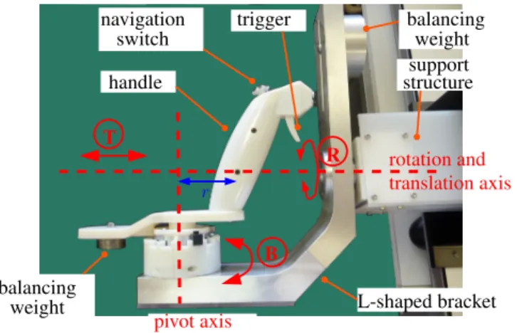
The master interfaces are mainly dedicated to the control of the instruments, which represents the most demanding task. The proposed new master console consists of two identical control handles with 3DoFs (see Fig. 12d), each aimed at controlling one of the instruments of the slave system. It comprises a handle shaft, designed to be gripped by the operator, mounted onto an L-shaped moving bracket (see Fig. 9). The bracket can rotate and translate with respect to a support structure along a single horizontal axis. The translation (range = [0, 90] mm) and rotation of the bracket (range = [−160o, +160o]) are used to respectively control the translation tzand rotation θzof the associated instrument. The shaft of the handle is connected to the bracket by a revolute joint, so that the handle can be moved with respect to the bracket along a circular trajectory of radius r = 70 mm. The angle B of the shaft with respect to the bracket controls the bending β of the tip of the concerned instrument. The master to slave mapping is illustrated in Figure 10 and in Table II.
The joints are passive, but the handle is statically balanced using counterweights attached to the back part of the handle and to the top of the vertical bar of the L-shaped bracket.
The offset r between the pivot axis and the handle allows to approximately reproduce the trajectory of the tip of the instrument when it bends but by using rigid links only. Hence, the operator moves his/her hands as if he/she were holding the distal tips of the instruments (i.e. the effectors), which allows for a very intuitive teleoperation of the instruments. This is adapted to surgeons who wish to independently control the DoFs of the instruments, but also to users who prefer to directly control the Cartesian position of the tip of the instruments.
Additionally, the architecture allows to reproduce the kine-matic singularity of the instrument since, when in a straight position, the operator’s hand is located on the rotation axis between the bracket and the support structure.
Each control handle is fitted with a trigger actuated using the index finger, which is used to control the opening / closing of mechanical instruments.
C. Control of the main endoscope
It is key to provide an easy and intuitive control of the endoscopic camera without having to release the handles, in order to change the position of the camera and to move the
r T R B pivot axis rotation and translation axis handle navigation switch trigger balancing weight support structure balancing weight L-shaped bracket
Fig. 9: Close view of one of the newly designed master interfaces.
in the camera frame horizontal plane horizontal plane
plane of the instrument
tz B θz β R Z Zmax T
Fig. 10: Joint positions mapping between the DoFs of one master handle and the DoFs of the corresponding instrument.
workspace of the instruments with respect to tissues. To do so, each control handle is fitted with a small four-way (North-South (N-S) / West-East (W-E)) navigation switch at its top end. Each switch can be moved with the thumb and allows two DoFs of the endoscope to be controlled simultaneously. The mapping between the navigation switches and the DoFs of the endoscope and cradle can be programmed. The most intuitive combination is to use one switch to control endoscope deflections (left/right, up/down) and the other to control the endoscope translation (N-S direction) and endoscope rotation (W-E direction). The activation in one direction is used to actuate the corresponding DoF with a predefined velocity. The endoscope stays still after the switch has been released.
DoF Movement Range Master/slave mapping T Translation [0, Tmax] = [0; 90] mm tz=tTzmax
maxT
B Rotation (for bending) [−Blim, Blim] with Blim≤ 170o
β = βmax
BlimB
R Rotation (around horizontal axis) [−160o, 160o] θz= R
TABLE II: Features of master handles and master/slave mapping. The rotation for bending is limited to ±Blim by movable hardware end-stops, allowing to modify the scaling factor K = βmax
Blim for B → β between 1 and 4.
Fig. 11: Main steps of the surgical workflow of STRAS v2. ”S.” represents the main surgeon, ”A.” represents an assistant. Step numberings are those used in Section V.
D. Assessment of telemanipulation usability
The usability of the novel system regarding the telemanip-ulation has been assessed on a laboratory setting. Twenty-five medical professionals (endoscopists and surgeons) were asked to perform precise manipulation tasks (requiring instruments and endoscope motion, similar to those reported in [21]) with the robotic system. A training stage (less than 10 min.) took place under the guidance of engineers, which consisted in performing a different task. Each test task lasted 3 minutes, and the aim was to perform a maximum number of targetings. After the session, the users were asked to score the intuitive-ness of use on a 5-point scale (1 meaning not intuitive - 5 very intuitive). The mean score obtained for the intuitiveness was 3.4, meaning that users were satisfied with the usability of the system. In particular, the limited precision of the slave system reported in Section III-B does not seem to affect the usability of the telemanipulated system.
V. SURGICAL WORKFLOW OFSTRASV2
The typical workflow to use STRAS v2 can be described as follows (see Fig. 11). Typical times are given in brackets.
Preparation
1) System set-up: The master console and the slave cart are prepositioned in the operating room, plugged and powered on. The endoscope is connected to the Storz light source and fluid management system (∼ 5 min).
2) Start-up and calibration: The computer on the master side is started and the ”STRAS” application is launched (∼ 1 min). Since all subsystems are equipped with incremental encoders, references have to be taken on every joint. Master interfaces are calibrated by manually bringing each joint to the limits of its range (∼ 20 s). The calibration of the slave system is started from the Graphical User Interface and automatically performed (∼ 3 min). At the end of this stage, all joints are automatically brought to a parking position.
Overall, this preparation takes around 10 minutes for two persons.
Reaching operation site
3) Insertion of endoscope: The endoscope is navigated manually towards the operating site by using the on-board joystick to orientate the head of the endoscope (see Fig. 12).
4) Securing endoscope onto the cradle: The cart is approached and the cradle is positioned by moving the height and inclination thanks to the remote controller and by adjusting translation and rotation from the master interface if required. Overall, the cart and cradle provide 7 DoFs, and it is possible to completely tune the position and orientation of the cradle in order to engage the handle of the endoscope, while minimizing motions on the handle. The endoscope’s handle is then clamped onto the cradle. This stage requires the intervention of an assistant.
5) Insertion of instruments: The flexible shafts of the instruments are manually inserted into the channels and the motors’ housings are installed inside the T/R modules as described in Section III A-c.
Operation
6) Teleoperation: The surgeon controls 10 DoFs (+ grasper opening / closing). If necessary, an assistant can use manual instruments inserted inside the central channel. 7) Change of instruments: During the procedure, it may
be necessary to withdraw the instruments without mov-ing the guide, for instance to exchange grasper and electrical knife. Modularity allows to change the in-struments: (1) the instrument’s tip is brought in a straight configuration and the corresponding T/R mod-ule is brought in the most proximal position; (2) The instrument module is then manually detached from the
supporting T/R module, and the instrument is retrieved from the channel and unplugged if necessary; (3) the replacing instrument is inserted into the channel as in the ”insertion stage”.
End of operation
8) Retrieval of the system: At the end of the surgical procedure, instruments are retrieved, the endoscope is detached from the cart and it is taken out manually, either using the on-board joystick or in a standby mode (motors deactivated).
VI. EXPERIMENTS AND RESULTS
One of the medical targets of STRAS v2 is the treatment of tumors in the rectum and in the sigmoid colon. STRAS v2 has been used to perform ESD in vivo on animal models (pigs). The objectives of these preclinical trials were to assess the robotic system, to evaluate the contribution of the robot with respect to conventional endoscopy and to the manual AnubiscopeTMplatform, to identify potential issues and effect of wear and tear on the system working and to get feedback from surgeons.
For this purpose, quantitative data obtained from the ex-periments have been compared with results reported in [6] for ESD performed with conventional endoscopes and with the manual AnubiscopeTMplatform from Karl Storz. A single user, a pilot general surgeon (Andras Legner) with no previous experience in flexible endoscopy, or in ESD, was in charge of all experiments, as also proposed in [6].
A. Robotic set-up
For each procedure STRAS v2 was used with one monopo-lar electrical instrument (hook or knife with insulated tip) in the right channel and one grasper (toothed or fenestrated) in the left channel. The electrical instrument was connected to a ValleylabTM generator and it was controlled by two pedals independently of the STRAS v2 robotic system. The initial preparation stage of the robot, which requires no interaction with animals, was done by the engineering staff of the ICube laboratory.
For the trials, the scaling factor for bending between master and slave was fixed at 1 : 1 by placing the hardware end-stops on the master interface to Blim= 90o. Velocity references for the motors controlling bending, rotation and translation of the instruments were limited by the software to 50% of the actual nominal velocities.
Lumen insufflation was performed using the standard Karl Storz Xenon 100 system connected to the main endoscope. Fluid management (camera rinsing, smoke sucking) was con-trolled directly with the endoscope’s handle by an assistant.
B. Surgical procedure
Eight animals were included in the study. One to three ESDs were performed on each animal under general anesthesia, at locations between 10 cm and 25 cm from the anal verge, for a total of 18 performed ESDs. The study protocol was approved by the Institutional Ethical Committee on Animal
Experimentation. (ICOMETH No.38.2011.01.018). The fol-lowing protocol was used (see Fig. 11, 12, and 13), similarly to the typical sequence of manual ESD [26] (except for a possible removal of stage 3).
1) Marking of the lesion boundary using an electrical instrument.
2) Injection of a 10% glycerol solution mixed with methy-lene blue into the submucosa using an injection therapy needle.
3) For 10 ESDs, a precut was performed around the marked area.
4) Dissection.
5) Retrieval of the specimen using the STRAS endoscope. Three variants of the protocol have been used: (a) with a pre-cut performed with an endoscope, (b) with a prepre-cut performed with STRAS and (c) without precut. In variant (a), stages 1 to 3 were performed by an endoscopist with a conventional endoscope and standard instruments. In variant (b), stages 1 to 3 were performed by a surgeon by teleoperating STRAS. A non-robotic injection needle was inserted inside the central channel for stage 2. In variant (c), stage 3 was not performed. Indeed, a precut is arguably less useful when working with STRAS than when using conventional endoscopes, because the platform allows the operator to retract tissues from a distant point of view.
C. Results
The trials represent more than 17 hours of active operation with STRAS. Twelve ESDs could be completed satisfactorily. Technical issues were encountered in six of the procedures: For procedures #2, #3 and #4 (performed in animals 1 and 2) insufflation problems prevented to correctly expose tissues and made the surgical intervention extremely difficult. This problem had not been detected during ex-vivo testing and during the first in vivo procedure. The main origin was air leaking out of instrument channels. The problem was later solved by adding rubber sealing rings between the instruments and the working channels. For procedure #6, the robotic system became unusable after 42 minutes of dissection, after a wire broke inside an electric bundle. The origin of the problem was detected, but it was not possible to repair on site. This is the only failure directly related to the robotic features of the system. Finally, for procedures #10 and #15, the electrical insulation at the tip of the insert of the electrical instrument was defective because the insert had been used intensively beforehand. This resulted in a low efficiency of the dissecting tool and a largely decreased dissection precision. No spare electrical knife/hook inserts were available to replace the defective one at the time of the procedure. This problem can also occur with conventional manual instruments after multiple uses.
Quantitative and qualitative analyses were performed for the 12 procedures that could be successfully completed. Welch’s t-tests (α = 0.05) were used for continuous variables com-parisons and Fisher’s exact test (α = 0.05) was used for boolean variables. The areas excised were 1717 ± 955 mm2. For procedure #7 a perforation was detected at the end of the
(a) Endoscope insertion (b) endoscope clamping onto the cradle
(c) Set-up of the instruments modules inside the T/R modules (d) Teleoperation
Fig. 12: Four stages regarding the use of STRAS v2 for an intraluminal procedure.
(a) Marking of the lesion boundary (b) Injection of glycerol solution (c) Precut with STRAS (not for all ESD)
(d) During dissection (e) End of dissection (f) Retrieved specimen
dissection and was closed using a clip. This is more (1/12) than for experiments with the manual AnubiscopeTM platform in [6] (0/9), however the difference is not significant (p ∼ 1). This is also significantly less (p = 0.04) than for experiments with standard endoscopes (8/16) [6] .
Figure 14 shows durations of the stages during the experi-ments. Since lesions excised have different sizes, a reference lesion of 3 cm × 3 cm in size was considered for comparison purposes. Equivalent times were computed for precut (by normalizing with respect to the perimeter) and for dissections (by normalizing with respect to the surface). A quick learning curve (4 procedures) appears for the time required to manually insert the endoscopic device, which from then necessitates only 2 minutes. For other stages, durations tend to decrease as more procedures are performed but no limit seems to have been reached yet. The equivalent time for procedure #9 was particularly long, and this can retrospectively be attributed to the onset of the electrical instrument’s insulation problems.
For the 8 cases where a precut was performed, the lesion areas were on average 1609 mm2 (between 220 mm2 and 3460 mm2) and dissection times were on average 34.25 min. (between 4 min. and 93 min.). The mean dissection speed (defined as the area dissected divided by the duration of the dissection) obtained with STRAS is 64.44 ± 34.88 mm2/min and it can be compared with those reported in [6] for conventional endoscopes (35.95 ± 18.93 mm2/min) and the AnubiscopeTM platform (23.98 ± 5.02 mm2/min). Dissection speed is found to be significantly higher with STRAS than with the manual AnubiscopeTM platform (p = 0.01) and higher with STRAS than with conventional endoscopes but not significantly (p = 0.06). Dissection speeds between variants (a) and (b) were also compared to assess if the way the precut was performed had an impact on the dissection. They were found to be not significantly different (p = 0.47).
For procedures performed with variant (c), a direct quan-titative comparison with [6] is not possible. However we compared procedure speeds (defined by the dissected area divided by the procedure duration) between variants (b) and (c) for which the procedure was completely performed with STRAS. No significant difference was found (p = 0.66) between the group with precut (25.57 ± 15.78 mm2/min) and the group without precut (33.14 ± 23.25 mm2/min). This justifies a posteriori that precut is not really required with such surgical platforms.
VII. DISCUSSION
A. Analysis of results
These experiments show that STRAS is a robotic system which is suitable for preclinical trials. STRAS allows a single user to perform all the surgical tasks of the ESD procedure on his/her own, whereas the manual AnubiscopeTM platform requires two skilled manipulators. In the reported experiments, the assistant was only in charge of very simple tasks: con-trolling fluids and injecting the glycerol solution to lift the mucosa. In addition, the comfort of use is largely improved. The surgeons who have telemanipulated the system are satis-fied by the ease of use provided by the master interfaces as
variant (a) variant (b) variant (c)
Fig. 14: Durations for the 12 procedures performed with STRAS. For comparison purposes, equivalent times have been computed for a reference lesion of dimensions 3 cm × 3 cm. Procedures are presented by protocol variants and in chronological order for each variant.
reported in Section IV-B. The novel interfaces also improve the adaptability since the ranges of the master interfaces and the scaling factors between master and slave can be tuned.
Initial insufflation problems have been solved on a long-term basis. Electrical insulation problems are due to the intensive use of instrument inserts, which have been left unmodified in the robotic device. Only one failure, due to electrical wiring breakage, can be ascribed to the robotic system. One perforation of the mucosa was caused during the 12 procedures but the difference is not statistically significant with respect to experiments with the manual AnubiscopeTM platform. Additionally STRAS allows to significantly increase the dissection speed for ESD procedures, by a factor of more than 2, with respect to the manual AnubiscopeTMplatform.
Durations variations have appeared between consecutive procedures, which might be explained by the following factors. (1) Lesions have various sizes and positions with respect to the endoscope. (2) Materials: Different kinds of effectors were tested and instruments shafts were changed after several uses. (3) Medical conditions vary, with particular proceedings imposed by strong peristalsis or very thin mucosa. Because of the important number of possible factors and their variability, it was not possible to identify which have preponderant effects. The experiments have shown that the degrees of freedom and the repeatability provided by the robotic system are sufficient for precise and dexterous surgery. The subsequent analysis of master and slave data recorded during the tasks has shown that software velocity limits were punctually reached for the translation and rotation of the instruments. This means that at these moments the instrument could not exactly follow the references provided by the surgeon. Users have not noticed these discrepancies, which have never exceeded 0.5 second. Moreover, all motions performed by the surgeon could be tracked by raising software limits and using the nominal capacities of the actuators.
Applicable forces practically appeared sufficient to grasp, lift and pull tissues and allowed the electrical instrument to safely dissect the mucosa and submucosa. Necessary forces evaluated in [24] (1 N) are slightly higher than the forces which can be applied by bending the instrument (0.9 N) (see Table I). However, in working conditions rotation and translation can help to provide higher forces.
The development of the robotic system was mainly focused on the assistance during the surgical stage of the procedure. For the initial insertion stage, the key feature of the pro-posed design is that the surgeon is directly in control of the endoscope and he/she can feel the interactions between the endoscope and the tissues, while simply and easily controlling the direction of the endoscope using the joystick. Dissections areas were between 10 cm and 25 cm from the anal verge, which is consistent with experiments reported with the manual AnubiscopeTMplatform. For such depths, the navigation of the endoscope does not require large deflection. For the moment, it is therefore not possible to draw conclusions concerning the suitability of this design for more distal targets. ESD can also be performed in the stomach. For these preclinical trials we focused on the rectum, where the risk of perforation is known to be higher because the submucosa is thinner. However, the mobilities and ranges of the cart DoFs would allow access for transoral procedures.
After these procedures, no significant deterioration of the robot was observed. Steering wires had to be re-tensioned to reduce dead zones and backlash. Wears also appeared on the instruments coating, as normally expected.
B. Comparison with other existing devices
Currently, only a few robotic systems based on flexible shafts and allowing for complete intraluminal surgical pro-cedures have reached the level of preclinical trials.
ViaCath, initially developed by Endovia was brought to the level of preclinical trials [16]. It provided highly articulated flexible instruments (6 DoFs per instrument) by using two consecutive two DoFs bending sections in addition to the trans-lation and rotation of the whole instrument from the proximal side. However, dexterity was obtained at the cost of limited applicable forces (0.5 N for the equivalent of bending) because the flexible sections were lacking compression resistance [17]. In addition, the instruments had to be inserted together with the main endoscope, which resulted in difficult insertion stages [17]. A second version using rigid links was developed to overcome these limitations, but no in vivo tests were reported. MASTER, originally developed by Nanyang Technological University, has already reached the level of clinical trials [27]. It is arguably the most advanced available device. It is based on a standard dual-channel gastroscope equipped with articulated arms attached at the distal tip. Each instrument can be translated with respect to the distal end of the endoscope and has 3 successive revolute joints providing a wrist to the effector. The use of rigid joints together with the attachment of the instruments to the distal end of the endoscope allows for the application of strong forces (up to 5 N for the equivalent of bending) [25]. However, with this architecture the endoscope is
not used as a guide for instruments and no additional channels are available. It is therefore necessary to use an overtube, it is not possible to easily change the instruments during the procedure, and a standard endoscope may be required to perform some parts of the procedure [27]. Most importantly, the endoscope has to be manually controlled at the tableside by a second endoscopist.
Instruments of STRAS have less DoFs than MASTER and ViaCath. However, since triangulation is passively created by the distal shell, all 3 DoFs of the instruments are completely available to perform surgical maneuvers. In vivo trials have shown that this is sufficient for procedures such as ESD.
With respect to MASTER and ViaCath, STRAS has brought novel valuable features at the level of preclinical trials for intraluminal surgical endoscopy. (1) The complete system can be teleoperated, hence avoiding the need of an assistant to manipulate the endoscope; (2) the system is modular: the instruments are independent of the endoscopic guide; (3) the endoscope serves as a guide for the instruments. (2) and (3) together allow to safely insert the endoscope inside the gastrointestinal tract and to change the instruments during the procedure, without requiring endoscope displacement; (4) Teleoperation of instruments and of the endoscope is intuitive even for surgeons not familiar with flexible endoscopes.
Dissection times reported in this article are longer than those reported for preclinical ESDs with MASTER [28]. However, comparisons are not straightforward because the mean dimensions of the excised lesions are much larger in our study. In addition, the conditions are different, since the results reported in [28] were obtained in the stomach, where ESDs are arguably easier because of a thicker submucosa [26] and of more free space for positioning.
C. Remaining limitations
For complete solo surgery, remote control of the fluids should be provided to the surgeon at the master console, as proposed in [19]. Before securing the endoscope onto the cradle, the cradle positioning has to be partly controlled from the master console. To facilitate this stage it could be interesting to control all cradle motions by using the remote controller located at the cart side.
The development of this second version of the robotic prototype was made while focusing on ESD procedures. Con-sequently, the end effectors initially provided were limited to graspers and electrocoagulation tools. The trials have allowed to validate the architecture of the instruments made of a hollow bendable shaft and of an insert equipped with an end-effector. More complex procedures may require other effectors, such as scissors, clip appliers or needle holders. These could be quite easily adapted to existing shafts, subsequently providing them with 3 DoFs. Highly dexterous tasks, such as suturing, may arguably benefit from additional DoFs.
The length of the flexible part of the current prototype (65 cm) does not allow to reach targets further than the descending colon or the stomach. Working with longer endoscopes would require higher torques at the motor level for large deflections of the endoscope. Delays due to friction would also appear
for complex shapes of the flexible shafts. However, from our past experience working with longer flexible sytems[29], we are confident that the concept of STRAS v2 can be successful when used for longer endoscopes and instruments.
For acceptance of the robotic device, the decrease of the procedure’s duration should compensate the time required to prepare the operating room. With the current robotic system, set-up time is limited to 15 minutes, all included. Nevertheless, integrating sterile drapes to respect sterility procedures in the operating room could increase set-up time. The development of these clinical features is currently under investigation. Our plan for next developments is first to validate the usability in clinical trials for ESDs in the rectum and colon, before trying to enlarge the scope of medical procedures.
VIII. CONCLUSIONS
STRAS v2 is a teleoperated modular robotic system based on flexible, steerable instruments and endoscope. Modularity allows for the use of the robot for all stages of intraluminal surgery and for the exchange of instruments. Neither an ad-ditional endoscope nor overtube are required. Two motorized instruments and the endoscope provide 10 DoFs (+ grasper opening / closing), which can be intuitively teleoperated using specifically designed master interfaces. This allows a single surgeon to perform all surgical tasks of ESD without assistance, which is impossible with manual platforms.
STRAS v2 has been successfully used in 12 ESD proce-dures. Its usability has been proven and improvements have been observed in dissection speed with respect to manual systems. This substantiates the interest of this novel robotic system for intraluminal surgical procedures, especially for surgeons with little experience with flexible endoscopes ma-nipulation. STRAS must now be adapted to the sterility requirements of the operating room. Improvements are also considered to reduce mechanical stress on flexible shafts when setting up the instruments.
ACKNOWLEDGMENTS
This work was supported by a FUI project (ISIS) and by SATT-Conectus Alsace. This work was supported by French state funds managed by the ANR within the Investissements d’Avenir program under the ANR-11-LABX-0004 (Labex CAMI) and ANR-10-EQPX-44 (Robotex Equipment of Ex-cellence) references. Authors would like to thank Karl Storz for providing the AnubiscopeTM platform. Authors would like to thank Guy Temporal and Christopher Burel, for their professional proofreading of this document.
REFERENCES
[1] B. Yeung and T. Gourlay, “A technical review of flexible endoscopic multitasking platforms,” International Journal of Surgery, vol. 10, no. 7, pp. 345–354, 2012.
[2] G. Spaun et al., “A multitasking platform for natural orifice translumenal endoscopic surgery (notes): a benchtop comparison of a new device for flexible endoscopic surgery and a standard dual-channel endoscope,” Surgical Endoscopy, vol. 23, p. 2720, 2009.
[3] C. Thompson et al., “Evaluation of a manually driven, multitasking platform for complex endoluminal and natural orifice transluminal endoscopic surgery applications,” Gastrointestinal Endoscopy, vol. 70, no. 1, pp. 121–125, July 2009.
[4] L. L. Swanstr¨om et al., “Development of a new access device for transgastric surgery,” Journal of Gastrointestinal Surgery, vol. 9, no. 8, pp. 1129–1137, 2005.
[5] B. Dallemagne and J. Marescaux, “The ANUBISTMproject,” Minimally
Invasive Therapy and Allied Technology, vol. 19, no. 5, pp. 257–261, 2010.
[6] M. Diana et al., “Endoluminal surgical triangulation: overcoming chal-lenges of colonic endoscopic submucosal dissections using a novel flexible endoscopic surgical platform: feasibility study in a porcine model,” Surgical Endoscopy, vol. 27, pp. 4130–4135, 2013.
[7] V. Vitiello et al., “Emerging robotic platforms for minimally invasive surgery,” IEEE Reviews in Biomedical Engineering, vol. 6, pp. 111– 126, 2013.
[8] M. Remacle et al., “Transoral robotic surgery (TORS) with the medrobotics flexTM system: first surgical application on humans,”
Eu-ropean Archives of Oto-Rhino-Laryngology, vol. 272, no. 6, pp. 1451– 1455, June 2015.
[9] P. Patel et al., “Evaluation of a novel flexible snake robot for endoluminal surgery,” Surgical Endoscopy, vol. 29, no. 11, pp. 3349–3355, November 2015.
[10] J. Ruiter et al., “Robotic control of a traditional flexible endoscope for therapy,” Journal of Robotic Surgery, vol. 7, no. 3, pp. 227–234, 2013. [11] J. Ding et al., “Design and coordination kinematics of an insertable robotic effectors platform for single-port access surgery,” IEEE/ASME Transactions on Mechatronics, pp. 1612–1624, 2013.
[12] “http://www.transenterix.com/.” [13] “https://www.virtualincision.com/.” [14] “http://www.titanmedicalinc.com/.”
[15] M. Piccigallo et al., “Design of a novel bimanual robotic system for single-port laparoscopy,” IEEE/ASME Transactions on Mechatronics, vol. 15, no. 6, december 2010.
[16] R. Rothstein et al., “Computer-assisted endoscopic robot system for advanced therapeutic procedures,” Gastrointestinal Endoscopy, vol. 59, no. 5, p. 113, 2004.
[17] D. J. Abbott et al., “Design of an endoluminal notes robotic system,” in IEEE International Conference on Intelligent Robots and Systems, San diego, October 2007.
[18] S. J. Phee et al., “Master and slave transluminal endoscopic robot (MASTER) for natural orifice transluminal endoscopic surgery (NOTES),” in IEEE International Conference on Engineering in Medicine and Biology, Minneapolis, USA, 2009, pp. 1192–1195. [19] J. Ruiter, “Robotic flexible endoscope,” Ph.D. dissertation, University of
Twente, 2013.
[20] A. Arezzo et al., “A miniature robotic device applicable to a flexible en-doscope for the surgical dissection of gastro-intestinal tract surface neo-plasms,” Italian Patent FI2013A000 055, extended PCT/IB2014/059 939, 2013.
[21] A. De Donno et al., “Introducing STRAS: a new flexible robotic system for minimally invasive surgery,” in IEEE International Conference on Robotics and Automation, Karlsruhe, May 2013, pp. 1213–1220. [22] A. De Donno et al., “Master / slave control of flexible instruments for
minimally invasive surgery,” in IEEE/RSJ International Conference on Intelligent Robots and Systems, Tokyo, November 2013, pp. 483–489. [23] L. Zorn et al., “Motorised and modular instrumentation device
and endoscopy system comprising such a device,” French Patent WO/2013/132 194, 2013.
[24] T. Ranzani et al., “A novel device for measuring forces in endoluminal procedures,” International Journal of Advanced Robotic systems, vol. 12, no. 116, 2015.
[25] Z. Sun et al., “Enhancement of a master-slave robotic system for natural orifice translumenal endoscopic surgery,” Annals Academy of Medicine Singapore, vol. 40, no. 5, pp. 223–230, 2011.
[26] ASGE Technology Comitee, “Endoscopic submucosal dissection: Tech-nology status evaluation report,” Gastrointestinal Endoscopy, vol. 81, no. 6, pp. 1311–1325, 2015.
[27] S. Phee et al., “Robot-assisted endoscopic submucosal dissection is effective in treating patients with early-stage gastric neoplasia,” Clinical Gastroenterology and Hepatology, vol. 10, no. 10, pp. 1117–1121, October 2012.
[28] K. Ho et al., “Endoscopic submucosal dissection of gastric lesions by using a master and slave transluminal endoscopic robot (MASTER),” Gastrointestinal Endoscopy, vol. 72, no. 3, pp. 593–599, 2010. [29] B. Bardou et al., “Control of a multiple sections endoscopic system,” in
IEEE International Conference on Intelligent Robots and Systems, 2010, pp. 2345–2350.