Olivier Frey*, Jörg Rothe, Flavio Heer, Peter D. van der Wal, Nico F. de Rooij and Andreas
Hierlemann
Multisite monitoring of choline using biosensor
microprobe arrays in combination with CMOS
circuitry
Abstract: A miniature device enabling parallel in vivo
detection of the neurotransmitter choline in multiple brain regions of freely behaving rodents is presented. This is achieved by combining a biosensor microprobe array with a custom-developed CMOS chip. Each silicon micro-probe comprises multiple platinum electrodes that are coated with an enzymatic membrane and a permselective layer for selective detection of choline. The biosensors, based on the principle of amperometric detection, exhibit a sensitivity of 157 ± 35 µA mM-1 cm-2, a limit of detection of
below 1 µM, and a response time in the range of 1 s. With on-chip digitalization and multiplexing, parallel record-ings can be performed at a high signal-to-noise ratio with minimal space requirements and with substantial reduc-tion of external signal interference. The layout of the inte-grated circuitry allows for versatile configuration of the current range and can, therefore, also be used for func-tionalization of the electrodes before use. The result is a compact, highly integrated system, very convenient for on-site measurements.
Keywords: head stage; in vivo; microelectrode;
microelec-trode array; neurotransmitter; real-time monitoring.
*Corresponding author: Dr. Olivier Frey, Federal Institute of
Technology Zurich (ETHZ), Department of Biosystems Science and Engineering, Bio Engineering Laboratory, Mattenstrasse 26, CH-4058 Basel, Switzerland, Phone: +41 61 387 3344, Fax: +41 61 387 3994, E-mail: [email protected]
Jörg Rothe, Flavio Heer and Andreas Hierlemann: Federal Institute
of Technology Zurich (ETHZ), Department of Biosystems Science and Engineering, Bio Engineering Laboratory, 4058 Basel, Switzerland
Peter D. van der Wal and Nico F. de Rooij: Federal Institute of
Technology Lausanne (EPFL), Institute of Microengineering, Sensors, Actuators and Microsystems Laboratory, 2000 Neuchâtel, Switzerland
Introduction
With the continuous growth of worldwide neurosci-ence research activities, a trend toward addressing more
difficult biological questions can be observed [7, 20]. This is, on the one hand, a consequence of the highly complex nature of the central nervous system and, on the other hand, due to the availability of more advanced technol-ogy and fabrication processes, especially in microtechnol-ogy. Miniature tools for direct interaction with neuronal cells and tissue at single-cell and subcellular length scales become more and more pervasive [21, 34, 40].
Although wire microelectrodes with a single record-ing site at the tip still may constitute the dominant experi-mental method for electrophysiological recordings [11], several groups start to employ microfabricated probe technology, in which multiple microelectrodes can be integrated on a single probe shank that then access mul-tiple brain sites in parallel at relatively low tissue damage [5, 9, 14, 17, 30]. Arrays of such microprobes and electrodes can be precisely arranged in two or three dimensions, ena-bling a spatially highly resolved mapping of in vivo neural circuitry and interpretation of network-related phenom-ena [1, 2, 8, 23, 26, 32]. Multisite recordings have also been performed with wire arrays; however, their assembly is, in most cases, limited in precision and number of electrodes, as they are assembled manually [37, 41].
In brain tissue, neurochemically active molecules are central for intercellular communication, and their monitoring is highly important for understanding brain functions and their relevance with respect to neural dis-eases such as epilepsy, Alzheimer’s disease, and Parkin-son’s disease [15]. The neurotransmitter acetylcholine, for example, is highly involved in cognitive processing and attention in the central nervous system. It is important for synaptic plasticity and is associated with a variety of behavioral aspects, such as motivation and reward [12, 13].
Biosensors offer the possibility to monitor several neu-rotransmitters at suitable temporal resolution. Choline, the breakdown product of freshly released acetylcholine, can be detected via the enzyme choline oxidase, which catalyzes the oxidation of choline to betaine and hydro-gen peroxide (H2O2). H2O2, in turn, can be electrochemi-cally oxidized at the surface of a platinum (Pt) electrode,
providing a current that is directly proportional to the choline concentration. Good spatial resolution can be achieved by direct immobilization of the used enzymes on top of the microelectrodes.
Several groups have presented such biosensors in the past years. Many of these sensors are based on insulated Pt wires or carbon fibers that are exposed at the tip to create a disc or cylinder microelectrode [19, 24, 27, 28, 31, 35, 38]. Enzyme coating is either performed by dip coating [19, 24, 27] or by dispensing small amounts of enzyme solution over the active electrode area [31, 38]. Further-more, electrochemical deposition methods with a variety of polymers have been used [28, 35]. They allow for better spatial control, and tedious serial deposition of several electrodes has been replaced by a parallel coating of only targeted and biased electrodes.
Recently, enzyme electrodes have also been integrated on microfabricated probes carrying multiple electrodes [5, 6, 25, 39]. The utilized functionalization methods are similar to previously used single-electrode functionaliza-tion methods (drop/dip coating) and are thus limited in upscaling to larger multielectrode ensembles.
Looking at the technological developments, the appli-cations under investigation, and the requests of the neu-roscience community, two trends become evident: (a) Use of arrays of implantable biosensors for monitoring
of neurotransmitters in different brain areas in parallel (b) Conduction of trials and recordings in freely behaving,
task-performing animals in order to correlate concentration variations of specific neurotransmitters to observable behavior.
Both trends entail stringent technology requirements [4]. Precise fabrication of microelectrode arrays is crucial for accurate positioning and definition of the inter-electrode spacing. Reliable functionalization protocols for multi-ple microelectrodes to create biosensor arrays have to be developed, as well as electrochemical setups capable of acquiring many signals in parallel featuring the needed performance and reliability. Array compatibility of the microelectrode fabrication and biosensor functionaliza-tion procedures, as well as multiple signal acquisifunctionaliza-tion, are mandatory prerequisites. Furthermore, noise reduc-tion techniques to enable low analyte detecreduc-tion limits and small overall device dimensions in order to not impede the animal during experiments are important issues.
We recently developed a biosensor microprobe array [17], based on silicon microfabrication, and the cor-responding array-compatible electrode functionaliza-tion techniques through electrochemical methods. Our next step included combining this array with a CMOS
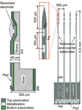
Figure 1 Layout of the microprobe comb consisting of four identical
shanks of 6.5 mm length, each comprising two recessed 50 μm × 150 μm working electrodes (zoomed view) and one 40 μm × 500 μm electrode, used either as reference or counter electrode.
Cross-sections AA′ and BB′ show the layer structures at the recessed electrode and pad site, respectively.
(complementary metal oxide semiconductor) chip that has been developed in our laboratory and that hosts cir-cuitry for performing electrochemical experiments, as well as on-chip analog-to-digital conversion. With the overall system packaged in a compact and flexible way, it can be mounted directly on a rodent’s head and features a minimum of cable connections even for many electrodes due to on-chip integrated multiplexing circuitry. This technological approach constitutes a step toward three-dimensional neurochemical mapping of local brain areas.
Materials and methods
Silicon microprobes
The microprobe array has a comblike design, consisting of four parallel, identical shanks at 550 µm pitch, featuring a length of 6.5 mm and a cross-sectional area of 40 µm × 100 µm (Figure 1). Each shank comprises two Pt microelec-trodes, located at 500 µm distance from the tip and featuring an area of 50 µm × 150 µm. Both electrodes are recessed by 10 µm in order to create a small compartment that protects
the biosensitive membrane during tissue insertion and removal. The distance between the electrodes is 200 µm. On each shank, a larger, 40 µm × 500 µm, non-recessed elec-trode, located in the middle of the shank, can be used either as pseudo-reference or a counter electrode. When used as a reference electrode, the Pt layer is electrochemically covered with a 5-µm-thick silver layer that is partially transformed into AgCl. The present geometry of the comb has been chosen to target the medial prefrontal cortex of a rat’s brain.
The microprobe arrays have been fabricated using standard micromachining techniques on 4-in., 300-µm-thick silicon wafers. Potassium hydroxide (KOH) wet etching has been used to create the recesses of the working electrodes. This has the advantage that the inter-connection lines can be laid across the inclined side walls appearing during the KOH etch. The substrate is insulated (bottom passivation) with, first, a 200-nm-thick layer of thermal silicon oxide and, second, by a deposition of 200 nm of low-pressure chemical vapor deposited (LPCVD) silicon nitride. A 130-nm Pt with a 20-nm tantalum adhe-sion layer has been deposited by using e-beam evapora-tion and structured by means of a lift-off process. The top passivation consists of 200-nm LPCVD silicon nitride that has been removed at the electrode and contact pad sites through reactive ion etching to expose the underlying Pt. The microprobe has been shaped with two deep reactive-ion etching steps. First, the wafer has been thinned from the backside to the intended shank thickness (40 µm). Second, the contours of the microprobes have been etched from the front side, which released them from the bulk. Small joints are retaining the microprobe combs in the wafer grid, where they are stored and can then be released
immediately before use (for further details and figures of each individual step, refer to ref. [17]).
CMOS chip
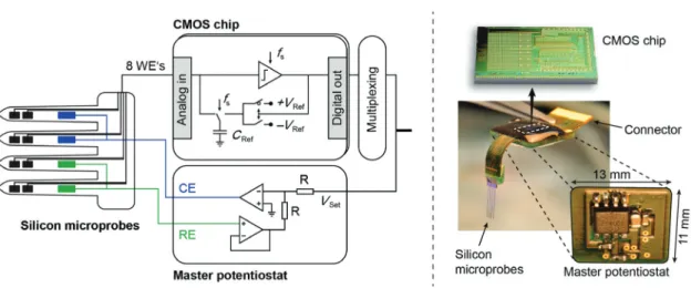
The schematic of the device and its electrochemical princi-ple are depicted in Figure 2. An external master potentiostat controls the voltage difference between the reference elec-trode and all working elecelec-trodes. The electrochemically generated current on each individual working electrode is measured in parallel using CMOS integrated circuitry.
The CMOS chip has been fabricated in an industrial 0.6-µm, 5-V 3M2P CMOS process (X-FAB, Erfurt, Germany) and has been previously presented in detail [22, 29]. It comprises 24 current read-out channels, eight of which are used for the microprobe comb to simultaneously record from the eight integrated working electrodes. The current measurement scheme is based on a very compact sigma-delta converter. It makes use of the double-layer capaci-tance of the electrode-electrolyte interface to integrate the charge. The potential of the electrode is kept at a certain voltage by adding or subtracting charge from the double-layer capacitance with the precharged reference capacitor CRef. The amount of charge that is delivered per time is the current that flows through the working electrode.
The converter circuit features very low noise, and the full-scale current range, IFS, can be set by changing the sampling frequency, fs, the reference capacitance, CRef, and the reference voltage, VRef, which is used to charge CRef:
IFS = ± CRef×VRef×fs.
Figure 2 Schematic and photograph of the implantable microprobe device.
The CMOS chip and master potentiostat are assembled and electrically interconnected on a custom-made, flexible PCB. Non-transparent epoxy glue is used to protect the wires and the light-sensitive CMOS chip.
The large adjustable range, IFS, allows, on the one hand, for recording of very low currents in the measure-ment mode, and, on the other hand, for application of large currents for electrochemical depositions on the electrodes.
Device packaging and setup
A custom-designed printed circuit board (PCB) hosts a CMOS chip, a microprobe comb, and additional electri-cal components for the master potentiostat. The PCB has a flexible front part allowing for vertical implantation of the microprobe comb into the brain and flat position-ing and fixation of the electronic part on the animal’s skull by using dental acrylic glue and fixation bolts. This results in a compact assembly on the animal’s head with minimal disturbance for the animal while performing the experimental task. The CMOS chip is glued on the top of the PCB and wire bonded. On the bottom, two operational amplifiers (AD8539, Analog Devices, Norwood, MA, USA), two resistors (1 MΩ), and two capacitors (100 nF, 10 µF) for electrical decoupling form the master potentiostat, which holds the bulk at a defined potential controlled by the reference electrode. All parts are encapsulated in non-transparent epoxy glue for electrical and mechanical protection. On the backend of the device, a zero-insertion-force connector can be connected for electronic control and data acqui-sition. VSet defines the potential difference between the reference electrode and all working electrodes.
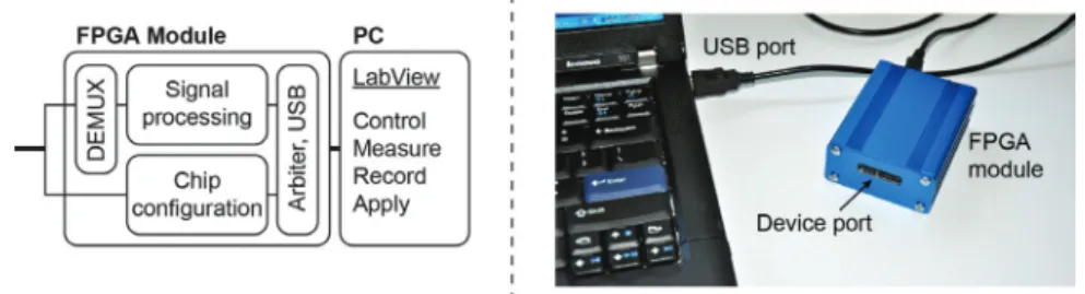
A thin, flexible cable is used to connect the device to a field-programmable gate array (FPGA) module for chip control and data processing (Figure 3). The FPGA per-forms filtering and decimating of the output signals of the sigma-delta modulators to yield high-resolution signals. Therefore, two filters have been implemented, a cascaded integrator-comb filter, used as a first filter stage, and an exponential moving average filter as a second stage. The FPGA is connected via USB to a conventional laptop
running Labview that records the measurement data and supplies power to the system.
Electrode functionalization
The biosensor principle is based on amperometric detec-tion of peroxide using an enzymatic membrane, deposited on a Pt microelectrode. For the detection of choline, the enzyme choline oxidase from Alcaligenes sp. (ChoOx, EC 1.1.3.17) has been used and immobilized on the Pt surface by electrochemically aided adsorption. Briefly, the whole array has been immersed into a freshly mixed deposition solution comprising the enzyme, the protein albumin from bovine serum (BSA), and the cross-linker glutaraldehyde (all from Sigma Aldrich, Switzerland). The application of a sequence of electrical potentials (25 times 1.8 V vs. Ag/AgCl) increases the protein concentration at the biased electrode, which initiates a local cross-linking and the for-mation of gelatinous membrane containing ChoOx. The detailed deposition protocols have already been described elsewhere [17]. Here, they have been applied without any external potentiostat but by directly using the integrated circuitry. Owing to the high deposition potential used, the current range of the sigma-delta converters has been set to IFS = ± 58.9 µA (CRef = 10 pF, VRef = ± 1.9 V, fs = 3.1 MHz). For the deposition, an external Pt wire and Ag/AgCl wire have been used for the counter and reference electrodes, respectively. The adhesion of the membrane to the elec-trode surface has been improved by a coating of (3-ami-nopropyl)triethoxysilane (Sigma) via vapor silanization before deposition.
Subsequently, m-polyphenylenediamine (m-PPD, Sigma) has been electropolymerized on the micro-electrodes by cyclic voltammetry (20 cycles, 0–0.9 V vs. Ag/AgCl, 50 mV/s) and used as permselective layer to sub-stantially reduce interference signals from other electro-active species such as dopamine (DA) and ascorbic acid (AA). Also present in the extracellular fluid of the brain, they are oxidized at a similar potential as used for the
detection of H2O2. The integrated circuits of the CMOS chip have been used for potential cycling with following set-tings: CRef = 1 pF, VRef = ± 1.0 V, fs = 1 MHz, i.e., IFS = ± 1.0 µA.
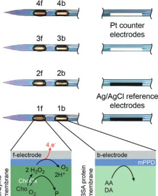
As both deposition procedures rely on electrochemi-cal principles, they can be spatially controlled and can be executed in parallel on multiple electrodes of the array. In general, the microelectrodes closer to the tip (xf in Figure 4) on each shank are coated with an enzyme membrane. On the adjacent electrodes (xb), an “inactive” BSA-pro-tein-only membrane is deposited. The latter is used as a control or “null” sensor in a differential measurement mode. The protein membrane is required to match the dif-fusion properties of the sensitive microelectrodes.
After functionalization, the devices are stored dry at 4°C.
Electrochemical recording setup
Calibration measurements have been conducted in 50 ml phosphate-buffered saline solution at either 37°C or room temperature (22–25°C). The liquid has been continuously stirred using a standard magnetic stirrer. No Faraday cage was used. Small volumes of choline, DA, and AA stock solu-tions have been added manually at constant time inter-vals to obtain defined analyte concentrations. It has been assumed that homogenous dissolution is achieved in less than a second. All eight working electrodes have been polar-ized at 0.65 V using the probe-integrated thin film Ag/AgCl reference and Pt counter electrodes. The current range has been set to IFS = ± 2.5 nA (CRef = 0.1 pF, VRef = ± 0.1 V, fs = 250 kHz).
Recordings in agarose gel (1%) have been performed at room temperature with the same electrochemical set-tings. The biosensor electrodes have been placed 5 mm below the surface using a micromanipulator. The tip of a glass micropipette filled with 200 µM colored choline solu-tion has been posisolu-tioned at a distance of ~300 µm from electrode 4a (see top view in Figure 7) by using a second micromanipulator. Collinear insertion and slow injection rates ( < 100 nl/min) are important to avoid cracks in the gel, which would lead to inhomogeneous, non-spherical choline diffusion.
Results and discussion
Device characteristics and functionality
The used microfabrication processes allowed for precise and reproducible fabrication of the microprobe arrays
Figure 4 Photograph of the microprobes with functionalized
electrodes.
The front electrodes (xf) are covered with a choline oxidase enzyme membrane. The back electrodes (xb) do not comprise any active enzyme but a slightly larger amount of the BSA protein only. On all electrodes, front and back, an additional interference rejection layer (m-PPD) has been deposited (schematics).
with ± 2 µm accuracy with respect to the designed masks. Straight and smooth shanks with a very sharp tip reduce tissue damage and brain surface deformation during implantation (see Figure 4 and ref. [17]). The same process can be used for future layouts that are different in shank number and length, as well as in the number and posi-tion of the microelectrodes on each shank, and targeted at specific brain regions in different experimental setups. Besides such rigid microprobes, other groups have pre-sented flexible constructs that may better match the mechanical properties of the soft brain tissue [10, 33, 36]. Sufficient long-term biocompatibility has been observed; however, precise electrode positioning may be more difficult.
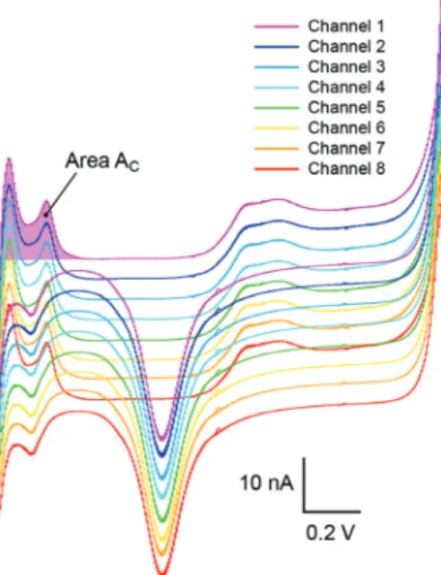
The quality of the Pt electrodes has been assessed electrochemically. Figure 5 shows an overlay of 10 con-secutively recorded cyclic voltammograms (CVs) of all eight microelectrodes. All CVs have been recorded in par-allel in 1 M de-aerated H2SO4 in the potential window of -0.42 to 1.20 V versus the shank-integrated Ag/AgCl refer-ence electrode at 100 mV/s. Adequate Pt electrode quality
and reproducibility is demonstrated, and a high current/ voltage resolution of the CMOS circuitry is evident, as clearly resolved single peaks in the hydrogen region are visible on all eight electrodes. The roughness factor (effec-tive surface/geometric surface) of the Pt electrode is 1.1 (8200 µm2/7500 µm2) and compares well to previous
pub-lications [16, 17]. It has been calculated by the measured charge associated with a 100% hydrogen coverage, which corresponds to the positive region between -0.42 to 0.00 V (shaded area AC in Figure 5) upon assuming 210 µC/cm2
charge transfer [3]. CVs have been measured before every microelectrode functionalization for the purpose of elec-trochemical cleaning of the electrodes and for controlling the Pt quality, to check on inter-electrode cross-talk and to assess the general electrical functionality of each channel.
The CMOS chip has a power consumption of 25 ± 5 mW. Its small size of 6.5 mm × 3.0 mm allows for construction of a small head stage, suitable for freely behaving animals. More important, electrochemical signals of many elec-trodes are digitized on-chip, making it less susceptible to external interferences such as electromagnetic fields or cable distortions. Linearity and electrical noise within the smallest current range allow for resolving currents below 0.5 pA. While the use of CMOS technology allowed for a substantial miniaturization of the signal acquisition part, the overall size reduction of the head stage is, currently, on the one hand, limited by the PCB that is required to
Figure 5 Ten consecutive CVs of each electrode in 1 M de-aerated
H2SO4 (-0.42 to 1.20 V vs. Ag/AgCl, 100 mV/s).
Curves have been recorded in parallel using eight current read-out channels of the CMOS chip (curves are offset for better visibility).
connect to the CMOS chip via wire bonds and, on the other hand, by the size of the cable connector, which has to be robust and reliable during experiments. The whole setup including the FPGA module and laptop is very compact and therefore very convenient for field experiments.
Biosensing characteristics and application
Figure 4 shows a photograph of the eight coated micro-electrodes. Membranes of the same type (enzyme vs. BSA membranes) have been deposited in parallel. The picture shows identical and spatially well-controlled depositions on all electrodes with minimal unspecific adsorption on the shank. The larger electrodes in the middle of shanks 1 and 2 have been used as integrated Ag/AgCl reference electrodes. The Ag/AgCl layer nicely covers the underlying Pt. A potential of +68.4 ± 0.8 mV (n = 6) versus a standard liquid-phase Ag/AgCl reference electrode (3 M KCl) was reproducibly measured in PBS (pH 7.2).
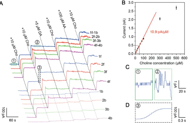
Raw data of simultaneously recorded in vitro current response curves of a calibration measurement of all choline biosensors are presented in Figure 6A. The elec-trodes have been functionalized as depicted in Figure 4. The measurement was performed 1 day after membrane deposition. For better visibility, the single recorded curves have been offset. “xf” and “xb” denote the signals of the active and inactive electrodes, respectively. “xf-xb” shows the differential curves, with the inactive electrode signals being subtracted. The biosensors show good reproducibil-ity of all electrodes with respect to sensitivreproducibil-ity and selectiv-ity. Active biosensor electrodes instantaneously respond to 10 µM choline injections, which correspond to concen-trations expected in the extracellular fluid of a rat brain. The sensitivity was determined to be 11.8 ± 2.6 pA/µM, cor-responding to 157 ± 35 µA mM-1 cm-2 (n = 35) with a linear
range up to 100 µM (Figure 6B). The standard deviation reflects the sensitivity variation obtained by using biosen-sors of different deposition runs and different fabrication batches. The m-PPD layer efficiently blocks DA and AA. The choline signal is not altered owing to the presence of DA and AA in the PBS solution. In some cases, a small increase in current is visible for DA or AA on the active electrode (xf). When diffusion and rejection properties are comparable for both electrodes, a similar contribution is also observed on xb and can be effectively removed by using the differential method (xf-xb). The rejection char-acteristics of xf and xb, however, are not always the same, but have to be adjusted by proportional scaling of the signals on the basis of the differences in the recorded cali-bration curves. If the difference between corresponding
electrodes, xf and xb, is > 20%, biosensors are not used. Owing to the parallel nature of the deposition process, the inter-electrode variability of the response to choline is as low as 6.9 ± 4.6% (n = 10, with n being the number of microprobe arrays), which represents the relative stand-ard deviation calculated from the standstand-ard deviations of the sensitivities of the four biosensors of each of the 10 microprobe arrays. Thus, biosensor sensitivities within a device vary by 7% on average. In some cases, we observed a small cross-talk ( < 5%) between adjacent electrodes (xf and xb). As this cross-talk was not consistent, we assume the reasons to be cross-contamination during deposition or electrical cross-talk. The temperature dependence was measured to be 0.3 ( = 2.75%) pA µM-1 °C-1 (n = 4).
The differential method significantly reduces the noise level to < 1 pA (peak-to-peak) in PBS, and to 3 pA at a choline concentration of 20 µM (Figure 6C). This results in a limit of detection of 0.25 and 0.8 µM, respectively (three times the background). It has to be mentioned here that the experi-ment was carried out on a conventional laboratory bench without Faraday cage. Neither magnetic stirring nor differ-ent manipulations of the experimdiffer-enter influenced the noise level, demonstrating the benefit of the circuitry integration.
Figure 6D shows the fast response time of the bio-sensor, which is on the order of 1 s. However, it is highly dependent on the method used for changing the choline concentration in the solution and may be even smaller when using a flow injection system. Further character-istics, such as biosensor shelf lifetime and interference rejection rates over time, can be found in refs. [17, 18].
One micromolar of peroxide produced a current signal of 24.9 pA (not shown in the graph). Considering that ChoOx produces two molecules of H2O2 per choline molecule, an efficiency of about 20% can be calculated, which gives an indication on the enzyme load and elec-tro-oxidation efficiency of H2O2. It further shows that the ChoOx-mPPD membrane has a good H2O2 permeability.
The usability of such a multielectrode configuration is illustrated in Figure 7A. Colored choline solution (200 nl) has been injected in the vicinity of the fourth shank, inserted in agarose gel (1%), which has been used here as a brain-mimicking substrate. While the expected spheri-cal diffusion can be observed optispheri-cally, the four biosen-sors are responding according to their location relative to the injection site. Figure 7B shows the derived concentra-tion distribuconcentra-tions at ti[s] = t0+i × 100 s for i = {1,…,7}.
Figure 6 (A) Simultaneously recorded response curves (raw data) of calibration measurements in PBS at 37°C. Aliquots of choline and the
two main interferents, DA and AA, were consecutively added to reach concentrations that can be expected in the extracellular fluid in the brain. “xf-xb” denote differential curves. (B) Calibration curve. (C) Close-up views (scaled with respect to the current axis) of curve 1f–1b at two different positions to demonstrate noise levels, and (D) close-up view of curve 1f (scaled with respect to time) to illustrate the response time. [Boxes indicating close-up views in (A) are not to scale for better visibility.]
Conclusion
The presented device is based on microelectrode fabri-cation and dedicated electrode functionalization so that truly simultaneous multisite neurochemical recording in freely behaving animals becomes possible. It has been realized by combining silicon-micromachined multishank probes with a versatile CMOS chip offering electrochemi-cal functionality.
Silicon microfabrication technologies allow for precise and custom-designed fabrication of microprobes of almost any desired shape and number, which can be equipped with multiple microelectrodes. Functionali-zation of these microelectrodes requires a reproducible and array-compatible method, i.e., a method that can be spatially controlled and is preferably parallel. Therefore, electrochemistry-based methods have been used for elec-trode cleaning, enzyme immobilization, and deposition of the anti-interference layer. The electrochemical proto-cols have been executed directly with the CMOS circuitry and do not require any additional equipment. This has become possible by the implementation of adjustable current ranges of the CMOS sigma-delta converters.
The key advantage of the chip integration is the digi-talization of the measured signals in immediate vicinity to the sensors. Given the favorable characteristics of the biosensors with regard to sensitivity, selectivity, detec-tion limit, and response time, the system enables parallel amperometric measurements at a very good signal-to-noise ratio, whereas no additional signal-to-noise contributions are picked up through connecting leads. This is crucial for reliable measurements in non-ideal environments with,
e.g., freely moving animals. Multiplexing of the signals of the different channels helps reduce the number of con-nections and helps minimize the dimensions of the flex-ible cable between the animal head stage and the control module. Integration of the potentiostat on chip for purely digital wire communication as well as wireless transmis-sion may be envisaged in future generations of the chip.
Finally, the compact control and acquisition module is very convenient for on-site recordings and integration into experimental setups. The devices are currently opti-mized and tested with freely moving rats showing impul-sive behavior performing the five-choice serial reaction time task. In semi-acute experiments, the devices have been implanted for recordings up to 2 weeks. The relatively short experimentation time is limited by the stability of the enzyme in vivo, which defines the functional lifetime of the device. In vivo stability of the sensor and the micro-probe as well as biocompatibility and the anticipated time span of use are important features to be addressed in the near future.
Acknowledgments: The biosensor microprobe
develop-ment was supported by the European integrated project NeuroProbes (EU IP IST-027017). The authors are grateful to the staff at the Microsystems Technology Division of the Centre Suisse d’Electronique et de Microtechnique (CSEM SA), Neuchâtel, Switzerland, for support during the fabri-cation process. Alexander Stettler of the Cleanroom Facil-ity at D-BSSE is acknowledged for CMOS post-processing.
Received January 27, 2013; accepted September 24, 2013; online first October 19, 2013
Figure 7 Recorded responses from four electrodes (A) and derived concentration profile at different time points (B) after a choline solution
has been injected at a distance of 300 µm from biosensor electrode 4f (see Figure 4). The insert in (A) shows the geometric layout of injec-tion point and electrode locainjec-tions.
References
[1] Aarts AAA, Neves HP, Puers RP, Van Hoof C. An interconnect for out-of-plane assembled biomedical probe arrays. J Micromech Microeng 2008; 18: 064004.
[2] Bai Q, Wise KD, Anderson DJ. A high-yield microassembly structure for three-dimensional microelectrode arrays. IEEE Trans Biomed Eng 2000; 47: 281–289.
[3] Bard AJ, Faulkner LR. Electrochemical methods: fundamentals and applications. 2nd ed. New York: Wiley 2001.
[4] Bucur B. Technological barriers in the use of electrochemical microsensors and microbiosensors for in vivo analysis of neurological relevant substances. Curr Neuropharmacol 2012; 10: 197–211.
[5] Burmeister JJ, Moxon K, Gerhardt GA. Ceramic-based multisite microelectrodes for electrochemical recordings. Anal Chem 2000; 72: 187–192.
[6] Burmeister JJ, Pomerleau F, Huettl P, et al. Ceramic-based multisite microelectrode arrays for simultaneous measures of choline and acetylcholine in CNS. Biosens Bioelectron 2008; 23: 1382–1389.
[7] Buzsáki G. Large-scale recording of neuronal ensembles. Nat Neurosci 2004; 7: 446–451.
[8] Campbell PK, Jones KE, Huber RJ, Horch KW, Normann RA. A silicon-based, three-dimensional neural interface: manufacturing processes for an intracortical electrode array. IEEE Trans Biomed Eng 1991; 38: 758–768.
[9] Cheung KC, Djupsund K, Dan Y, Lee LP. Implantable multichannel electrode array based on SOI technology. J Microelectromech Syst 2003; 12: 179–184.
[10] Cheung KC, Renaud P, Tanila H, Djupsund K. Flexible polyimide microelectrode array for in vivo recordings and current source density analysis. Biosens Bioelectron 2007; 22: 1783–1790.
[11] Dale N, Hatz S, Tian FM, Llaudet E. Listening to the brain: microelectrode biosensors for neurochemicals. Trends Biotechnol 2005; 23: 420–428.
[12] Dalley JW, Cardinal RN, Robbins TW. Prefrontal executive and cognitive functions in rodents: neural and neurochemical substrates. Neurosci Biobehav Rev 2004; 28: 771–784. [13] Dalley JW, McGaughy J, O’Connell MT, Cardinal RN, Levita L,
Robbins TW. Distinct changes in cortical acetylcholine and noradrenaline efflux during contingent and noncontingent performance of a visual attentional task. J Neurosci 2001; 21: 4908–4914.
[14] Errachid A, Ivorra A, Aguilo J, Villa R, Zine N, Bausells J. New technology for multi-sensor silicon needles for biomedical applications. Sens Actuat B Chem 2001; 78: 279–284.
[15] Fillenz M. In vivo neurochemical monitoring and the study of behaviour. Neurosci Biobehav Rev 2005; 29: 949–962. [16] Frey O. Biosensor microprobe arrays for in vivo monitoring of
neurotransmitters. EPFL Thesis 4614. 2010.
[17] Frey O, Holtzman T, McNamara RM, et al. Enzyme-based choline and L-glutamate biosensor electrodes on silicon microprobe arrays. Biosens Bioelectron 2010; 26: 477–484.
[18] Frey O, van der Wal PD, Spieth S, et al. Biosensor microprobes with integrated microfluidic channels for bi-directional neurochemical interaction. J Neural Eng 2011; 8: 066001.
[19] Garguilo MG, Michael AC. Amperometric microsensors for monitoring choline in the extracellular fluid of brain. J Neurosci Methods 1996; 70: 73–82.
[20] Garris PA. Advancing neurochemical monitoring. Nat Methods 2010; 7: 106–108.
[21] HajjHassan M, Chodavarapu V, Musallam S. NeuroMEMS: neural probe microtechnologies. Sensors 2008; 8: 6704–6726. [22] Heer F, Keller M, Yu G, Janata J, Josowicz M, Hierlemann A.
CMOS electro-chemical DNA-detection array with on-chip ADC. 2008 IEEE International Solid-State Circuits Conference – digest of technical papers 2008; 51: 168–604.
[23] Herwik S, Kisban S, Aarts AAA, et al. Fabrication technology for silicon-based microprobe arrays used in acute and sub-chronic neural recording. J Micromech Microeng 2009; 19: 074008. [24] Hu YB, Mitchell KM, Albahadily FN, Michaelis EK, Wilson GS.
Direct measurement of glutamate release in the brain using a dual enzyme-based electrochemical sensor. Brain Res 1994; 659: 117–125.
[25] Mattinson CE, Burmeister JJ, Quintero JE, Pomerleau F, Huettl P, Gerhardt GA. Tonic and phasic release of glutamate and acetyl-choline neurotransmission in sub-regions of the rat prefrontal cortex using enzyme-based microelectrode arrays. J Neurosci Methods 2011; 202: 199–208.
[26] Norlin P, Kindlundh M, Mouroux A, Yoshida K, Hofmann UG. A 32-site neural recording probe fabricated by DRIE of SOI substrates. J Micromech Microeng 2002; 12: 414–419. [27] Oldenziel WH, Beukema W, Westerink BHC. Improving the
reproducibility of hydrogel-coated glutamate microsensors by using an automated dipcoater. J Neurosci Methods 2004; 140: 117–126.
[28] O’Neill RD, Lowry JP, Rocchitta G, McMahon CP, Serra PA, O’Neill RD. Designing sensitive and selective polymer/enzyme composite biosensors for brain monitoring in vivo. Trends Anal Chem 2008; 27: 78–88.
[29] Rothe J, Lewandowska MK, Heer F, Frey O, Hierlemann A. Multi-target electrochemical biosensing enabled by integrated CMOS electronics. J Micromech Microeng 2011; 21: 054010. [30] Ruther P, Herwik S, Kisban S, Seidl K, Paul O. Recent progress
in neural probes using silicon MEMS technology. IEEJ Trans Elect Electron Eng 2010; 5: 505–515.
[31] Schuvailo OM, Soldatkin OO, Lefebvre A, Cespuglio R, Soldatkin AP. Highly selective microbiosensors for in vivo measurement of glucose, lactate and glutamate. Anal Chim Acta 2006; 573: 110–116.
[32] Seidl K, Herwik S, Torfs T, Neves HP, Paul O, Ruther P. CMOS-based high-density silicon microprobe arrays for electronic depth control in intracortical neural recording. J Microelectromech Syst 2011; 20: 1439–1448.
[33] Stieglitz T, Beutel H, Schuettler M, Meyer J-U. Micromachined, polyimide-based devices for flexible neural interfaces. Biomed Microdevices 2000; 2: 283–294.
[34] Stieglitz T, Schuetter M, Koch KP. Implantable biomedical microsystems for neural prostheses. IEEE Eng Med Biol Mag 2005; 24: 58–65.
[35] Tian F, Gourine AV, Huckstepp RTR, Dale N. A microelectrode biosensor for real time monitoring of L-glutamate release. Anal Chim Acta 2009; 645: 86–91.
[36] Tijero M, Gabriel G, Caro J, et al. SU-8 microprobe with microelectrodes for monitoring electrical impedance in living tissues. Biosens Bioelectron 2009; 24: 2410–2416. [37] Ulbert I, Halgren E, Heit G, Karmos G. Multiple
microelectrode-recording system for human intracortical applications. J Neurosci Methods 2001; 106: 69–79.
[38] Vasylieva N, Barnych B, Meiller A, et al. Covalent enzyme immobilization by poly(ethylene glycol) diglycidyl ether (PEGDE) for microelectrode biosensor preparation. Biosens Bioelectron 2011; 26: 3993–4000.
[39] Wassum KM, Tolosa VM, Wang JJ, Walker E, Monbouquette HG, Maidment NT. Silicon wafer-based platinum microelectrode array biosensor for near real-time measurement of glutamate in vivo. Sensors 2008; 8: 5023–5036.
[40] Wise KD. Silicon microsystems for neuroscience and neural prostheses. IEEE Eng Med Biol Mag 2005; 24: 22–29. [41] Zachek MK, Takmakov P, Park J, Wightman RM, McCarty GS.
Simultaneous monitoring of dopamine concentration at spatially different brain locations in vivo. Biosens Bioelectron 2010; 25: 1179–1185.