HAL Id: hal-02190131
https://hal.archives-ouvertes.fr/hal-02190131
Submitted on 22 Jul 2019
HAL is a multi-disciplinary open access
archive for the deposit and dissemination of
sci-entific research documents, whether they are
pub-lished or not. The documents may come from
teaching and research institutions in France or
abroad, or from public or private research centers.
L’archive ouverte pluridisciplinaire HAL, est
destinée au dépôt et à la diffusion de documents
scientifiques de niveau recherche, publiés ou non,
émanant des établissements d’enseignement et de
recherche français ou étrangers, des laboratoires
publics ou privés.
ON-CHIP PRE-TREATMENT OF BIOLOGICAL
SAMPLES FOR THE ISOLATION OF ADIPOSE
STEM CELLS (ASCs)
Marion Valette, Mathias Bouguelmouna, Mélanie Mariotte, Rémi Courson,
Marie-Charline Blatché, Amandine Girousse, Coralie Sengenes, Karine
Reybier, Anne Marie Gué
To cite this version:
Marion Valette, Mathias Bouguelmouna, Mélanie Mariotte, Rémi Courson, Marie-Charline Blatché,
et al.. ON-CHIP PRE-TREATMENT OF BIOLOGICAL SAMPLES FOR THE ISOLATION OF
ADIPOSE STEM CELLS (ASCs). Transducers, Jun 2019, Berlin, Germany.
�10.1109/TRANSDUC-ERS.2019.8808694�. �hal-02190131�
ON-CHIP PRE-TREATMENT OF BIOLOGICAL SAMPLES FOR THE ISOLATION
OF ADIPOSE STEM CELLS (ASCs)
Marion Valette
1,2,3, Mathias Bouguelmouna
1,3,Mélanie Mariotte
1,5, Rémi Courson
1,
Marie-Charline Blatché
1, Amandine Girousse
4, Coralie Sengenès
4, Karine Reybier
2and
Anne-Marie Gué
11
LAAS-CNRS, Toulouse, FRANCE
2PharmaDEV, Toulouse, FRANCE
3
Université Paul Sabatier Toulouse III, Toulouse, FRANCE
4STROMAlab, Toulouse, FRANCE and
5Faculté des Sciences et Techniques, Limoges, FRANCE
ABSTRACT
This study presents the development of an original 2-steps Lab-on-chip that aims at isolating Adipose Stem Cells (ASCs), cells of considerable interest for regenerative medicine, from complex biological samples. Based on hydrodynamic filtration, the device pre-isolates ASCs by removing cells with a diameter below 10µm such as red blood cells or lymphocytes.
KEYWORDS
Microfluidics, Dry Films, Stem Cells, Adipose Stem Cells, Hydrodynamic Filtration
INTRODUCTION
Adipose tissue has widely been only considered as a source of energy and fat storage. It is now considered as a rich source of multipotent stem cells: Adipose Stem Cells (ASCs). Due to their differentiation capabilities, ASCs became cells of considerable interest for regenerative medicine [1]. They are also of high interest for type II diabetes diagnosis. They are present in high quantity in adipose tissue and their migration and circulation in lymph nodes has been demonstrated [2]. Thus, the hypothesis of their circulation in blood is not excluded but no method exists to isolate them from blood. Unfortunately, a major difficulty is that ASCs do not present any specific physical characteristic: their diameter ranges from 10 to 40 µm and they do not have any specific antigen on their membrane. This paper presents a device (Lab-On-Chip) that aims at isolating ASCs from blood by using passive methods. To isolate them, we propose an original approach combining two complementary steps. The first one, based on hydrodynamic filtration, eliminates elements with a diameter below 10µm (red blood cells, platelets, etc.). The second one, based on immunologic exclusion, removes remaining hematopoietic cells. This paper is focused on the first part of the device.
MICROFABRICATION OF LAB-ON-CHIP
The manufacturing of the lab-on-chip was made possible by an efficient lamination-based technology. We used dry film photoresists, DF-10XX series (EMS), which are commercially available epoxy resists.
Processes with dry films are both cheaper and faster than with SU-8 and they are compatible with
microfabrication technologies [3].
A 4” glass substrate (Schott AF32, 500 µm thick) has been chosen to allow the visualization of flows in the chip. Two glass substrates were needed to realise the devices.
To create the fluidic inputs and outputs at precise positions, one of the two wafers was drilled, by nanosecond UV laser (351 nm).
Before patterning the channels, the drilled substrate underwent a surface treatment (piranha cleaning and O2
plasma, 800W for 5 min). The microfluidic channels were then created by lamination of dry films on the drilled wafer. DF-1005 and DF-1020 are respectively 5 and 20 μm thickness epoxy based dry films. A Shipley 3024 laminator was used with the following parameters: T = 100°C, 2.5 bars pressure and 0.5 m/min roll speed (Figure 1-Steps a) to f)).
After removal of protection films, the laminated layer was exposed to 365 nm wavelength light (264 mJ/cm2 for
40 μm layers) in a mask aligner (SUSS MicroTec MA-6). Post exposure bake was performed on a hotplate (5 min 30 sec at 100 °C). Cyclohexanone was then used as a developer (7 min) to remove uncrosslinked resist. Post exposure bake and development times depend on the thickness of the laminated layers.
The second glass wafer underwent a surface treatment (piranha cleaning and O2 plasma, 800W for 5 min) prior to
the lamination of a DF-1005 layer (Figure 1-Steps g) to h)). Prior to bonding, the resist on the drilled glass substrate underwent surface treatment: O2 plasma with a
Faraday cage, 200W for 2 min. The resist on the other glass substrate was not subject to any surface treatment.
A nanoimprimpt lithography tool (Nanonex), which allows controlling pressure, temperature and UV exposure, was used to bind the two processed glass wafers. The dry films were put in contact and the final wafer was placed in the Nanonex. The final wafer was first annealed at 65°C under a pressure of 30PSI during 2min. It was then annealed at 100°C and UV exposed during 20sec (365 nm) under a pressure of 60PSI (Figure 1-step i)). The final wafer was released when the wafer temperature reached 30°C.
Figure 1: Fabrication Process of microfluidic chips. a) Cleaning of the drilled glass substrate b) Lamination of DF-1005 c)-f) photolithography steps to build the microfluidic channels g) Cleaning of the second glass wafer h) Lamination of DF-1005 i) Bonding with Nanonex
EXPERIMENTAL SETUP AND
MATERIAL
The lab-on-chip was placed in a chip holder, which facilitates the injection of the samples without leakage. Visualizations of the experiments were done with the aim of an inverted fluorescence microscope (Zeiss Axio Observer).
Images were obtained in bright field or fluorescence (excitation source: Lumencor), captured with Andor camera (CMOS Zyla 4.2), processed with Micro-Manager and analysed with ImageJ.
A fluid pressure controller (Fluigent) was used to monitor the injection of solutions and samples.
We used a Coulter Counter Z2 to count (depending on the size) particles suspended in the sample.
Fluorescent polystyrene beads were used: ThermoFisher fluorescent polystyrene beads (diameters: 0.5 µm, 5 µm, 10 µm; excitation/emission: 505/515 nm) and Invitrogen fluorescent polystyrene beads (diameter: 15 µm; excitation/emission: 365/415 nm).
The experiments were also performed on living (native or cultured) cells. We used red blood cells from human blood provided by from EFS (French Blood Agency), France and mice blood isolated at STROMAlab. We also worked with THP-1, immortalized monocyte cells that were cultured in RPMI medium. We finally used native and cultured (in MEMalpha medium) ASCs, isolated from mice at STROMAlab.
PRINCIPLE OF HYDRODYNAMIC
FILTRATION
Yamada and Seki have introduced, in 2005, a new method to separate cells by size: hydrodynamic filtration [4]. The principle of this method is represented in Figure 2: side channels are connected to a main channel in which the sample is injected. The distance minimum between the centre of a particle and the wall is equal to the radius of the particle. Assuming that the centre of the particle follows a streamline, it is possible to filter particles depending on their size by draining fluid from a main channel through a side channel. The width of the flow to be collected in the side channel (from the main channel) determines the cut-off size or cut-cut-off radius. Particles with a radius smaller than the cut-off radius will flow in the side channels while particles with a bigger radius remain in the flow of the main channel.
Figure 2: Scheme of the principle of hydrodynamic filtration [4]
Hydrodynamic filtration is known as an efficient technique that allows leukocyte enrichment [4]. We aim at using this method to eliminate from blood cells with a diameter below 10µm i.e. red blood cells, platelets, lymphocytes and debris. After the filtration, only white blood cells with a diameter above 10µm such as granulocytes, monocytes and the cells of interest, ASCs, remain in the medium.
MODELING AND EXPERIMENTAL
Devices were designed according to the theoretical model developed in [5]. Volumetric flows in both main and side channels were determined by integrating the expression of the velocity profile in rectangular channels (Equation 1).
v y, z (1) The ratio of the flow rate in the main channel over the flow rate in a side channel depends on the geometry of the inlet channel and the cut-off radius (Equation 2).
∗ ∑
∑ (2)
We have designed our devices in order to obtain a 5 µm cut-off radius.
The first manufactured devices included 30 side channels orthogonal to the main channel. In order to validate dimensions and the geometry of the device, solutions of fluorescent polystyrene beads with different diameters (0.5 µm, 5 µm, 10 µm, 15 µm) have been injected.
As expected, we observed that the cut-off radius was equal to 5 µm: 5 µm diameter beads were filtered, 15 µm diameter beads were not filtered and those of 10 µm
Main channel Sample with particles
Main Output
diameter were partially filtered. However, these tests have also highlighted the formation of a flow instability resembling a vortex (Figure 3-a)) at the entrance of the side channel. This disturbance had an influence on the filtration and reduced the efficiency of filtration. Simulations with COMSOL 5.2 validated the behaviour of the fluid at the entrance of side channels (Figure 3-b)).
The design has then been optimized in order to optimize flow behaviour at the entrance of side channels and prevent disturbances from appearing. Side channels have been slanted to a 120° angle to the main channel. This optimized configuration is more biomimetic. Tests with fluorescent beads with the new device confirmed the disappearance of disturbances (Figure 3 c) and d)).
Figure 3: Observation of a solution of fluorescent polystyrene beads (diameter equal to 0.5µm) in PBS 1x with an inverted fluorescence microscope (Zeiss) in two different devices and simulations of the behaviour of the fluid in the corresponding devices. In the first configuration a) and b), side channels are orthogonal to the main channel. In the other configuration c) and d), side channels are tilted to 120-degree angle to the main channel
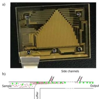
A picture and the working principle of the final device are presented in Figure 4.
This device is composed of a main channel (80 µm wide, 40 µm high) connected to two main inputs (input A for the sample and input B for the buffer) and one output (cells with a diameter d>10 µm flow through output C). Thirty side channels (30 µm wide, 40 µm high, tilted to a 120-degree angle) are connected to two side outlets (D1 and D2) in which are collected cells with a diameter below 10 µm.
Figure 4: a) Scheme of the device drawn on CleWin5 - Input A: Injected sample; Input B: Buffer; Output C: Cells with a diameter above 10 µm collected (ASCs are collected in this diluted medium); Output D1 and D2: Cells with a dimeter below 10 µm collected - b) Schematic of hydrodynamic filtration: in this example Red Blood cells (in red) are removed from the solution via side channels (D1/D2) and Adipose Stem Cells (in green) flow into output C
RESULTS AND DISCUSSION
Various parameters were explored to study separation efficiency and cell viability: applied couples of pressures, concentrations of the different cell populations.
Different couples of pressure (sample/ buffer: 300/350 mbar; 500/600 mbar and 800/950 mbar) were first tested. In accordance with theory, experiments showed that separation efficiency does not depend on applied pressure (Equation 2: Q*(r) does not depend on pressure). However, times of filtration are highly impacted by the choice of the couple of pressures. To filter 1 ml of sample, 30 min are required with the couple (sample/buffer) 800/950 mbar; 1h30min for the couple 500/600 mbar and 2h30min for the couple 300/350 mbar.
We then studied the separation efficiency by varying the concentration of labelled monocytes or labelled ASCs. The concentration of RBCs was first kept constant in order to determine the influence of the concentration of monocytes or ASCs on the behaviour of the sample and so on the separation efficiency. To facilitate the comparison between different solutions, we have defined a ratio r, which corresponds to the ratio of the concentration of RBCs over the concentration of THP-1 or ASCs.
(3)
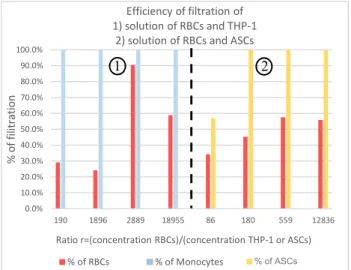
Results of the efficiency of filtration depending on the ratio r are depicted in Figure 5. All of the experiments demonstrated that we collect 100% of cells of interest (THP-1 or ASCs). The filtration of these cells does not depend on their concentration, which is encouraging for 120° Flow direction a) c) b) d) Flow direction Flow direction Flow direction a) b)
future tests with samples with rare cell events. However, the results of the separation of RBCs are not completely satisfying. The results of the experiments realised on samples containing RBCs and THP-1 (Figure 5-zone 1) fluctuate: the percentage of filtration of RBCs vary between 24 and 90%. On the contrary, results with solutions of RBCs and ASCs (Figure 5-zone 2) are more homogeneous but the percentage of filtration of RBCs is between 35 and 58%.
Such results might be explained by the existence of the margination phenomenon. As RBCs are more deformable than white blood cells and platelets [6], they migrate in the middle of blood vessels and leave stiffer cells close to the walls. The principle of our device needs the particles to be focalised close to the walls to be filtered. As the number of cells is high at the beginning of the filtration and has the cells are not yet ordered, RBCs can focalise close to the walls. However, the more the sample flows into the device, the less particles collide and the more RBCs migrate away from the walls, which implies a reduction of serration efficiency.
This device, regardless of the couple of pressures applied, is so able to pre-isolate ASCs without losing any of them. However, the filtration of RBCs is insufficient and has to be optimised. Another device with 100 side channels has been realised in order to improve RBCs filtration and reduce times of filtration. More experiments have to be conducted to find the optimized parameters to filter completely RBCs from the medium while collecting still 100% of cells of interest. Complementary experiments realised to determine cells viability are ongoing.
Figure 5: Efficiency of filtration different biological solutions depending on cell ratio. Red barres correspond to % of filtration of RBCs collected in side outputs (D1/D2), blue and yellow barres respectively correspond to % of filtration of THP-1 and ASCs collected in main output (C). Zone 1 and zone 2 respectively correspond to experiments done on solutions of RBCs + THP-1 or RBCs + ASCs. Concentrations were determined with Coulter Counter Z2.
CONCLUSION AND PROSPECTS
In conclusion, we demonstrated the capability of the hydrodynamic separation LOC to efficiently pre-isolate adipose stem cells from complex samples without
damaging cells, which has never been demonstrated before. As RBCs remain in the collected sample, other experiments to find optimized filtration parameters are ongoing.
The second part of the device, which aims at completely isolating ASCs by removing remaining hematopoietic cells (white blood cells) by “Cell Rolling”, is ongoing.
AKNOWLEDGEMENTS
This work was partially supported by the platform of micro and nanotechnologies of the LAAS-CNRS, Member of the French network RENATECH.
This work was partially supported by the French government through ANR under program PIA EQUIPEX LEAF (ANR-11-EQPX-0025).
The authors wish to thank IEMN (Institute of Electronics, Microelectronics and Nanotechnology) for their collaboration.
The authors wish thank DGA (French defense procurement agency) for their financial support.
REFERENCES
[1] L. E. Kokai, K. Marra, and J. P. Rubin, “Adipose stem cells: biology and clinical applications for tissue repair and regeneration,” Translational Research, vol. 163, no. 4, pp. 399–408, Apr. 2014.
[2] M. Gil Ortega et al., “Native Adipose Stromal Cells Egress from Adipose Tissue In Vivo: Evidence During Lymph Node Activation,” STEM CELLS, vol. 31, no. 7, pp. 1309–1320, Jul. 2013.
[3] R. Courson et al., “Low-cost multilevel microchannel lab on chip: DF- 1000 series dry film photoresist as a promising enabler,” RSC Advances, vol. 4, no. 97, pp. 54847–54853, Oct. 2014.
[4] M. Yamada and M. Seki, “Hydrodynamic filtration for on-chip particle concentration and classification utilizing microfluidics,” Lab on a Chip, vol. 5, no. 11, p. 1233, 2005.
[5] M. Fouet, “Microfluidique 3D et actionneurs magnétiques. De leur intégration à la préparation d’échantillons biologiques,” phd, Université de Toulouse, Université Toulouse III - Paul Sabatier, 2016.
[6] C. Bächer et al., “Anti-margination of microparticles and platelets in the vicinity of branching vessels,”
Biophysical Journal, vol. 115, no. 2, pp. 411–425, Jul.
2018.
CONTACT
A.M. Gué, tel: +33-05-61-33-62-08; gue@laas.fr LAAS-CNRS, 7 avenue du Colonel Roche, 31400 Toulouse, France 0.0% 10.0% 20.0% 30.0% 40.0% 50.0% 60.0% 70.0% 80.0% 90.0% 100.0% 190 1896 2889 18955 86 180 559 12836 % of filitration
Ratio r=(concentration RBCs)/(concentration THP-1 or ASCs) Efficiency of filtration of
1) solution of RBCs and THP-1 2) solution of RBCs and ASCs
% of RBCs % of Monocytes
1 2