Dynamic Properties of Dilute Bose-Einstein
Condensates
by
Dallin S. Durfee
Submitted to the Department of Physics
in partial fulfillment of the requirements for the degree of
Doctor of Philosophy
at the
MASSACHUSETTS INSTITUTE OF TECHNOLOGY
August 1999
@
Massachusetts Institute of Technology 1999- All rights reserved.
"o i
A uthor
.. . . . .* .. . . . . . .. .Department of Physics
August 30, 1999
C ertified by ...
. . .
.. ... .-.
. ...
Wolfgang Ketterle
Professor of Physics
Thesis Supervisor
A A ccepted by ... r. MASSACHUSETTS INSTITUTE OF TECHNOLOGY .... ... .. . .....
Thomas J reytak
Associate D "artment
Head for Education
Dynamic Properties of Dilute Bose-Einstein Condensates
by
Dallin S. Durfee
Submitted to the Department of Physics on August 30, 1999, in partial fulfillment of the
requirements for the degree of Doctor of Philosophy
Abstract
In this thesis, a new apparatus for the study of Bose-Einstein condensation is de-scribed, and the first two experiments performed with the new device are discussed. The new instrument was constructed for the creation of dilute gas sodium Bose-Einstein condensates, and features an optical quality quartz cell, a high-flux spin-flip Zeeman slower, a tightly confining magnetic trap, and a high-resolution imaging sys-tem. The theory, design, and construction of each component is discussed, including a detailed explanation of non-destructive dispersive imaging. Bose-Einstein condensa-tion was first achieved in the new apparatus in January of this year. Bose condensates consisting of 10 to 25 million atoms can be produced in this apparatus at a rate of two condensates per minute.
The first two experiments performed with the new instrument probed the dy-namic properties of dilute Bose condensates, allowing comparisons to be made with long standing theories of weakly-interacting degenerate Bose fluids. The first experi-ment was the study of "surface wave" excitations of Bose condensates. Standing and rotating quadrupole and octopole excitations were driven with a novel scanned optical dipole potential, a new tool which allows us to generate arbitrary two-dimensional perturbations to the trapping potential which confines the atoms.
The second experiment studied the transition from dissipationless to dissipative flow in a Bose condensate. This study, performed by "stirring" the condensate with a focused laser, provided the first experimental evidence for the existence of a critical velocity for dissipation in dilute gas Bose condensates. This experiment is discussed in the context of earlier studies of the critical velocity of superfluid liquid helium. Thesis Supervisor: Wolfgang Ketterle
Title: Professor of Physics
Acknowledgements
There are many people who deserve my gratitude for their role in the completion of my thesis work, and it would be impossible to mention them all in a few short paragraphs. There are several people in particular, however, who I wish to recognize specifically. First of all there are the many people which I have collaborated with and learned from while working in the sodium BEC lab at MIT. Most notable is Wolfgang Ketterle, the leader of the group. I have often been amazed at his knowledge and insight into all corners of atomic physics and all aspects of experimental technique - as evidenced by the phenomenal success of his lab. Furthermore, Wolfgang has a gift
for being able to explain complex ideas in an intuitive way, and he possesses an incredible amount of enthusiasm for his work. I should also thank Wolfgang for his efforts to keep the lab funded (as I should thank the funding agencies as well), making possible the unique experiments which
I have been fortunate to take part in. While writing this thesis, Wolfgang's comments have been
invaluable, and the time he dedicated to reading and criticizing my writing has had a large impact on the clarity of the text which I have written.
I should next thank the people who, with me, designed and built the new BEC experiment
-not only for their hard work and scientific knowledge, but also for their friendship during the long struggle to not only make the machine, but to make it work! Chris Kuklewicz was the first to join me in the early efforts on the new experiment. Chris has been a good friend from the start, and his skills in the lab and in front of a computer have helped to make the experiment reliable
and easy to control. Chandra Raman and Roberto Onofrio joined the effort soon after, bringing a large amount of experience with them. Chandra and I were soon bonded by a common enemy
- the temperamental ring dye laser, and Roberto, with his patience, good nature, and sharp sense
of humor has been the one who was always able to pull the group together. Michael Kdhl and Johnny Vogels both spent a year working on the new apparatus and both made large contributions. Michael's work with the scanning AOMs was particularly important for the experiments discussed in this thesis. And Jeff Gore, our undergraduate UROP, was both productive and pleasant to work with.
I also have great appreciation for the people who did early work in the Pritchard/Ketterle
ultra-cold atoms group for laying the foundation upon which my thesis work was based, and I am greatly indebted to the people I worked with on the old BEC experiment for the many things which they taught me. Mark-Oliver Mewes and Michael Andrews, who were already well-experienced when I joined the Ketterle lab, introduced me to laser cooling and magnetic trapping. Dan Stamper-Kum,
who joined the lab the same year that I did, has been a constant source of interesting conversation (on all topics both regarding physics and not), and has often taken the time to share his experience and insight with the group of us working on the new experiment. I also had the opportunity of working with several very bright post-docs while working on the older BEC experiment.
Klass-jan van Druten, Hans-Joachim Miesner, and Chris Townsend taught me a lot while I was a junior
graduate student. And when I first began work on the new apparatus, Hans was the person who most often lent me advice or a helping hand. I have also benefited greatly from my interactions with Shin Inouye, Joern Stenger, and Ananth Chikkatur, who joined the work on the older ex-periment after my attention had been turned to the new one. And I cannot forget to thank Carol Costa for her assistance dealing with all of the administrative tasks associated with experimental work, and Peggy Berkovitz and the people at the physics department education office and at RLE headquarters.
The many professors who introduced me to physics at Brigham Young University are responsi-ble for instilling in me the desire to scrutinize the inner workings of the universe, and for showing me the incredible predictive power of applied mathematics. Special thanks are in order for my undergraduate research advisor, J. Ward Moody, for giving me the knowledge and confidence nec-essary to pursue a graduate degree in physics. His leadership of the GoldHELOX project has had an immeasurable influenced on the students lucky enough to have worked on it.
A special thanks goes out to the people who encouraged and uplifted me outside of the halls
of science. My parents, who encouraged my educational pursuits in every way possible as I grew up, and who gave me a peaceful and happy home to study in, were also a great, although long-distance, support during my time at MIT. And my brothers and sister, as well as my wife's family, have always been ready to lend a listening ear or a helping hand, and Georgianna has been a great help over the last few weeks. My friends from the Cambridge first ward and all of the "Balldrivers" past and present gave me the opportunity to get away from the darkened lab now and then, and to see what was going on in the world outside of building 26.
The greatest of all thanks goes to my wife Memorie. During the good times and the hard times at MIT, she always did everything that she could to encourage, love, and support me. Throughout my graduate studies, she has always been the one to rebuild my confidence during times of dis-couragement. In short, she is the best friend that I've ever had. I especially have to thank her for her help and support while I was writing my thesis. Despite being nine months pregnant at the time that my thesis was completed, she worked hard to make sure that I was undisturbed and free from other concerns so that I could focus on my thesis writing. And with her background in physics, she has served as the primary reader of my thesis, in addition to searching out and photocopying countless references and creating many beautiful figures.
Lastly, I would like to thank my soon-to-be first-born child for waiting until after my thesis defense to be born. Due to a great number of circumstances, my thesis defense ended up taking
place on the very date that the child was due. I am grateful that this child had enough compassion on me to not to be born on the date prescribed by the doctors, allowing me to finish my work as a graduate student before beginning my life as a father. Furthermore, the hope, excitement, anticipation, and the impending responsibility of becoming a father has been a great motivator during my thesis writing.
Contents
1 Introduction and History 12
1.1 A Short History of BEC . . . 13
1.1.1 Early Studies of BEC . . . 13
1.1.2 BEC in Dilute Gases . . . 15
1.2 Characteristics of Alkali Gas Bose Condensates . . . 17
1.3 Outline of the Thesis . . . 18
1.4 My Work at MIT . . . 19
2 A New Apparatus for BEC Studies 21 2.1 Overview of the New Apparatus . . . 21
2.1.1 New Features of the Apparatus . . . .. . . 22
2.1.2 Why Sodium? . . . 24
2.2 Realization of BEC in the New Apparatus . . . 28
3 The Vacuum System 32 3.1 Vacuum Requirements . . . 32
3.2 Layout of the Apparatus . . . . 34
4.1 The Oven . . . . 4.2 The Zeeman Slower . . . . 4.2.1 Atomic Beam Slower Theory of Operation . . . . . 4.2.2 Spin-flip Zeeman Slowers. . . . . 4.2.3 Designing an Optimized Slower . . . . 4.2.4 Design and Construction Details of the New Slower 4.2.5 Performance of the New Slower . . . . 4.3 Magneto-Optical Trapping and Cooling . . . . 4.3.1 Implementation . . . . 4.3.2 Polarization Gradient Cooling . . . . 4.4 The Laser System . . . . 4.4.1 Locking the Laser . . . . 4.4.2 Generating Frequencies . . . . . . . . 4 1 . . . . 4 2 . . . 4 3 . . . . 4 4 . . . . 4 7 . . . 5 1 . . . 5 2 . . . 5 4 . . . 5 4 . . . 5 7 . . . 5 8 . . . 5 9 . . . 6 1
4.5 Controlling the Experiment . . . 63
5 Magnetic Trapping 64 5.1 Overview of Magnetic Trapping . . . . 64
5.2 Types of Magnetic Traps . . . 67
5.3 A Modified loffe-Pritchard Trap . . . 70
5.4 Subtleties of Magnetic Trapping . . . 78
5.5 Design and Construction of the New Magnetic Trap . . . . 81
5.5.1 Selection of Materials and Construction . . . . 82
5.5.2 Power Supplies and Switching . . . . 86
5.6 Evaporative Cooling . . . .. . .. . . 88
6 Imaging 90
6.1 Absorptive Imaging Methods . . . 90
6.1.1 Limits of Absorption Imaging . . . 91
6.1.2 Time-of-flight Imaging . . . 91
6.2 Dispersive Imaging Methods . . . 93
6.2.1 Non-destructive Imaging . . . 96
6.2.2 Rapid Sequences of Images . . . 96
6.3 Specifics of Our Imaging Layout . . . . 99
7 Optical Manipulation of Bose-Einstein Condensates 101 7.1 Theory of Optical Dipole Trap Operation . . . 103
7.2 Time Dependent "Arbitrary" Potentials . . . 105
7.2.1 Implementation of Scanned Dipole Potentials . . . 106
7.2.2 Limitations of Scanned Potentials . . . 110
7.2.3 Scanning Perturbations . . . Il 7.3 Future Experiments . . . 112
8 Interference of Bose Condensates 114 8.1 Condensate Interferometry . . . 115
8.1.1 Phase Diffusion Measurements . . . 115
8.2 Interference Patterns from Multiple Point Sources . . . 118
8.3 Interference of a Superfluid Ring or Vortex State . . . 122
9 Surface Waves 126 9.1 Hydrodynamic Excitations at Zero Temperature . . . 127
9.3 Experimental Realization of Surface Waves . . . .
9.3.1 1 = 2 "Quadrupole" Modes . . . .
9.3.2 1 = 4 "Octopole" Standing Waves . . . . 9.4 Conclusion . . . .
10 Dissipation, Critical Velocities, and Vortices
10.1 Critical Velocities in Landau's Model of Damping . . .
10.2 Relationship Between Critical Velocities and Vorticity .
10.3 Direct Search for Persistent Currents and Vortices . . .
10.4 Evidence of a Critical Velocity in a Dilute Bose Gas .
A Vacuum Conduction Analysis
B Recirculating Ovens . . . 131 . . . 132 . . . 134 . . . 137 140 . . . 141 . . . 142 . . . 145 . . . 146 151 155 C Magnetic Trapping and Evaporative Cooling -Varenna Summer School 1998 C. 1 Conservative Atom Traps . . . . C.2 Magnetic Trapping . . . . C.2.1 Quadrupole-type Traps . . . . C.2.2 loffe-Pritchard Traps . . . . C.2.3 Mode Matching . . . . C.2.4 Adiabatic Compression . . . . C.2.5 Figure of Merit for Magnetic Traps . . . . C.3 Evaporative Cooling . . . . C.3.1 Trap Loss and Heating . . . . D Magnetic Coils Wiring Diagram 10 159 . . . . 159 . . . . 160 . . . . 161 . . . . 162 . . . . 165 . . . . 167 . . . . 168 . . . . 169 . . . .170 172
E Imaging -Varenna Summer School 1998 175
E. 1 Techniques to Probe Bose-Einstein Condensates . . . 175
E. 1.1 Atom -Light Interactions . . . 176
E. 1.2 Absorptive and Dispersive Methods . . . 177
E. 1.3 Quantum Treatment of Light Scattering . . . 181
E. 1.4 Non-destructive Imaging . . . 182
E. 1.5 Other Aspects of Imaging . . . 183
Chapter
1
Introduction and History
The realization of Bose-Einstein condensation (BEG) in dilute alkali gases in 1995 [1, 2, 3] was the fruition of many years of work by various experimental groups. This achievement has allowed the study of a new quantum fluid with properties very different from superfluid helium, and has allowed physicists to control atoms with quantum limited precision similar to the way in which the optical laser provides the ultimate control over photons. Much of the theory of dilute gas condensates stems from decades-old work. But since the experimental realization of alkali gas condensates, many new properties have emerged - due to the finite number of atoms, the existence of internal degrees of freedom, and the inhomogeneity in these new systems. Although many of the early experimental studies of alkali gas condensates parallel older studies of liquid helium (the study of elementary excitations and sound, for example), other studies have been quite different from work done in liquid helium (including the observation of the spatial interference of overlapping condensates, and the time-resolved measurement of the condensate's formation). There are several key aspects of superfluid helium, however, which are just beginning to be explored in alkali gas Bose condensates. Among these are the existence of surface waves and a critical velocity for dissipationless flow. Studies of these phenomena are the major scientific results reported in this
1.1
A Short History of BEC
The phenomena of Bose-Einstein condensation was first described by Albert Einstein in 1925 [4]. While working on a generalization of Satyendra Nath Bose's theory of the quantum statistics of photons, Einstein realized that an ideal Bose gas, cooled below a critical temperature Tc, would have a macroscopic population of atoms in a single quantum state (the ground state). Stated this way, Einstein's prediction is not surprising; it makes sense that a large ground state occupation would occur if an ideal Bose gas were cooled to a temperature lower than the first excited state of the system. What is surprising, however, is the fact that (1) the temperature at which this occurs can be many times higher than the energy of the first excited state, and (2) the number of atoms in the ground state, as a function of temperature, was predicted to have a discontinuous derivative at the critical temperature T. Until the identification of superfluid helium as a Bose condensed system, however, there were many doubts as to whether this "ideal gas" phenomena would occur in real systems with interparticle interactions (the ideal gas Bose-Einstein condensate is discussed in many textbooks [5, 6], and will not be elaborated upon here).
1.1.1
Early Studies of BEC
Bose-Einstein condensation was first experimentally observed in superfluid liquid helium. In 1911 (just three years after producing the world's first sample of liquefied helium), Kamerlingh Onnes discovered that the density of liquid helium, as a function of temperature, had a sharp maximum near 2.2 Kelvin [7]. In 1926 Onnes and Dana measured another strange maxima in the specific heat near this same temperature [8] (this temperature later became known as the A-point, due to the A-shaped specific heat curve of liquid helium). In 1928, Wolfke and Keesom expressed the opinion that these measurements were the result of a phase transition in liquid helium (the higher temperature phase being labeled He I, and the lower temperature phase He II) [9, 10]. Other
strange properties of liquid helium associated with this phase transition were later discovered. For example, a sudden transition to extremely low viscosity [11, 12, 13] and extremely high heat conductivity [14] was seen to occur as the liquid was cooled through the A-point. And an extremely high thermomolecular pressure in He II (illustrated dramatically by the "fountain effect" [15]), and the adsorption of mobile "Rollin" films, many atomic layers thick, by any surface in contact with
He II were also reported.
In 1938 Fritz London, noting the similarity of the A-shaped heat capacity curve in liquid he-lium to the behavior of the heat capacity of an ideal gas near the BEC transition, proposed that superfluidity could be a manifestation of Bose-Einstein condensation [16]. This proposal, and its later verification, constitutes a landmark in modem physics. For the very first time a system had been discovered which was described by a macroscopic wavefunction, and to this date superfluid helium continues to be the subject of a considerable amount of research (for a more exhaustive treatment of superfluid helium, I refer the reader to some of the many books written on the subject
[17, 18, 19]).
Since the connection was made between BEC and superfluid helium, several similar systems have been discovered. In 1956 a theory was presented in which pairs of fermionic electrons formed composite bosons in superconductors, linking superconductivity to a phenomena very similar to Bose-Einstein condensation [20]. More recently, fermionic 3He has been shown to undergo a sim-ilar "BCS" transition [21, 22], and excitons in semiconductors have been made to Bose condense
[23, 24]. More "exotic" Bose condensates have also been theorized, including pion and kaon
con-densates in neutron stars [25, 26, 27], and the condensation of Higgs bosons responsible for the mass of elementary particles [28].
1.1.2 BEC
in Dilute Gases
The handful of Bose condensed systems mentioned in the paragraphs above have been studied in great detail over the years. But there has long been a desire for BEC in a long-lived, weakly interacting system which could be easily described from first principles. Long before dilute gas condensates were realized, the properties of weakly-interacting degenerate Bose gases had been studied theoretically in an attempt to gain insight into the more complicated, more strongly inter-acting superfluid helium. But until recently, no physical system had been realized which could provide a direct experimental test of these theories.
1.1.2.1 Development of the theory of weakly interacting bosons
Due to the complicated interactions between atoms in liquid helium, a full "first principles"
de-scription of the liquid helium phenomena discovered in the 1920's and 30's was not immediately available. Instead, two competing phenomenological theories emerged. The two-fluid model of Tisza and London considered liquid helium to be composed of two interpenetrating components, each with its own density and its own independent (to first approximation) flow field [29]. The so-called "normal" fluid was assumed to obey classical laws of fluid dynamics, while the "superfluid" component approximated an ideal gas Bose-Einstein condensate.
Landau's quantum hydrodynamic theory took a different view of superfluidity. Landau's theory was based on the quantization of classical hydrodynamics, de-emphasizing the quantum statistics of individual atoms and instead focusing on excitations in the fluid.
In 1947 Bogoliubov solved, from first principles, the ground state and fundamental excitations of a weakly interacting Bose gas [30]. Bogoliubov's assumptions in this study were not strictly valid for liquid helium (the temperature was assumed to be zero Kelvin, the "depletion" of the ground state was assumed to be small, and interactions were limited to mean-field interactions,
binary collisions, or hard sphere interactions). Nevertheless, this work showed that (A) Bose con-densation can occur in the presence of interactions, and (B) the low-lying excitations of the ground state in this system are phonons. Bogoliubov's theory, then, contained the essential elements of both Landau's and Tisza's theories, suggesting that the two were complementary, not opposing.
The study of theoretical systems with more complicated interactions soon yielded fruitful re-sults (including Penrose and Onsager's arguments for the existence of BEC in systems with more general types of interactions and, in particular, in liquid helium [31], and several works which low-ered the restrictions of Bogoliubov's assumptions [32, 33, 34]). The theoretical study of weakly interacting degenerate Bose systems, however, continued. Early work done included studies of the ground and lowest excited states of dilute Bose systems [35, 36], the fugacity of such systems
[37], the nature of the phase transition [38, 39], and sound propagation at finite temperature [40].
It wasn't until recently, however, that a physical system in which the interactions could well be described by a mean-field term was realized, allowing these theories to be directly tested.
1.1.2.2 Experimental realization of dilute gas Bose condensates
Since most atoms tend to form solids at the temperatures and densities required for BEC, one could easily be led to believe that dilute gas condensates are simply not possible. For a long time liquid helium (being the only known substance which did not become solid at absolute zero) seemed to be unique. In 1959, Bose-Einstein condensation in weakly-interacting spin-polarized hydrogen was proposed by Hecht [41], who predicted that the formation of molecules in atomic hydrogen could be suppressed all the way down to absolute zero by the use of strong magnetic fields. Hecht considered the nature of interparticle interactions in such a system, and concluded that they could possibly be described well by a hard-sphere model. By 1976 calculations had been done which confirmed that hydrogen would, indeed, remain a gas under these circumstances [42], and the experimental pursuit of BEC in spin-polarized hydrogen was begun.
The goal of BEC in hydrogen was eventually achieved in 1998 [43] (see [44] and [45] for further information about BEC in hydrogen). In the mean time, however, laser cooling and trapping techniques had been developed [46]. By combining these methods with the evaporative cooling technique developed for spin-polarized hydrogen, Bose-Einstein condensation in dilute alkali gases had been achieved in 1995 [1, 2, 3]. Since this time, many experiments have been performed probing the static and dynamic properties of weakly interacting Bose condensates, and dilute gas
BEC has been produced by twenty experimental groups (see [47] for a review of many studies
done and methods used in dilute gas BEC experiments).
1.2
Characteristics of Alkali Gas Bose Condensates
There are several properties which make alkali gas condensates of great interest. First of all, Bose condensates constitute a pure quantum state of matter. As such, they can be described by a macroscopic wave function with a global phase. The existence of this phase has been directly measured by interfering two condensates (see Chapter 8), and can be considered to be a result of the stimulated process by which condensates form [48]. The existence of a macroscopic wave function is responsible for the many strange properties of superfluid helium, and it is to be expected that similar properties should also exist in dilute gas Bose condensates. Alkali gas condensates, however, differ from superfluid helium in many ways. For example, as mentioned above, the alkali gas condensates which have been studied consist of a relatively dilute cloud of weakly interacting atoms, and are therefore highly compressible. The weak interatomic interactions can be described accurately by a mean-field, allowing comparisons to be made with the results of mean-field theories developed since the 1940's.
Another property of dilute gas condensates is the finite number (much less than Avogadro's number) of atoms involved. This results in a system with slightly different properties than a gas in
the thermodynamic limit [49]. In addition, dilute gas condensates are held in an inhomogeneous potential, resulting in a non-uniform condensate density in space. The inhomogeneous potential has the interesting result of spatially "separating" the condensate (which settles into a small "cold" cloud at the center of the trap) from the non-condensate atoms (which, having higher energies, are localized to a larger region of the trap).
The techniques used to make and study alkali gas condensates also allow for the existence of multicomponent condensates-either by mixing two different atoms or isotopes in a single cloud, or by putting a single species into multiple internal states. The tendency of the two components to intermix or phase separate, as well as the tendency for atoms in the condensate to change their internal state through collisions with other atoms, can be studied under various conditions. Multi-component condensates have been studied in Boulder by trapping atoms in two different hyperfine states [50]. Multicomponent "spinor" condensates have been studied here at MIT by putting the condensate into a superposition of mF spin states [51].
1.3
Outline of the Thesis
This thesis can be roughly divided into four sections. In the section following this introduction, I present a detailed description of a new apparatus which we have constructed for dilute sodium gas
BEC studies. Work on the new apparatus began about two and a half years ago, and its completion
was marked in January of this year with the production of its first Bose condensate. Since I was the student who initially began work on the new apparatus, and since this is the first thesis written which contains data produced by it, I will both document the relevant parameters of the apparatus, as they relate to experiments which have or will be done on it, and record some of the knowledge gained while building and optimizing it. The third section of this thesis contains a discussion of the first two experiments performed on the new apparatus. The first experiment studied collective
excitations with angular momentum, using time-averaged optical potentials to generate rotating surface waves on the condensate. I will briefly describe a second ongoing experiment, which was begun while I was writing my thesis. This study has measured the temperature rise in a condensate when it was "stirred" by a focused off-resonant laser, producing evidence for a critical velocity for dissipative flow. The last section of this thesis contains several appendices which augment the discussions found in the rest of the thesis.
1.4 My Work at MIT
The work described in this thesis only represents the second half of my research done at MIT. Before beginning the work described in this thesis, I participated in many experiments performed with our older BEC apparatus. I started working with Wolfgang Ketterle's group just six months before we produced the first sodium Bose condensate, and I consider myself fortunate to have been part of the many ground breaking experiments which took place in the first years after this event. These experiments have been reported on extensively in journal articles and in other students dissertations, and will only be briefly mentioned here.
In 1995 we observed our first evidence for the existence of a sodium gas Bose condensate [2, 52]. Soon afterwards we implemented a new type of trap for BEC studies using only DC magnetic fields (the "cloverleaf' trap [53]). The flexibility of this new trap facilitated the study of some of the condensate's collective oscillation modes [54]. The frequencies of these modes were compared to those described by mean-field theory and found to be in good agreement. In the spring of 1996, we used dispersive imaging methods to view condensates in-situ and non-destructively [55]. This method was later improved upon (see Chapter 6), and was used in many future experiments to record real-time "movies" of condensate dynamics [56].
condensates to a variety of RF magnetic fields, we demonstrated Rabi oscillations of the trapped condensate and studied non-adiabatic Landau-Zener transitions into untrapped mF states. These studies led to the creation of an "output coupler" which would allow an arbitrary fraction of the condensate atoms to be released from the trap [57]. Then, soon after this work was finished, we did an experiment in which we were able to observe the spatial interference pattern of two overlapping Bose condensates [58]. This experiment furnished the first direct proof of long-range coherence in a Bose condensate, drawing analogies between optical lasers and BEC. These two experiments constitute the first demonstration of an atom laser. In the course of these experiments we tried several methods to increase the time-of-flight of the expanding condensates (in order to increase the spatial period of the observed fringe pattern). One such attempt resulted in a sub-recoil atomic fountain [59].
Early in 1997, non-destructive imaging and the use of optical dipole forces allowed us to study the propagation of sound pulses in a Bose condensate [60, 61]. This work included the first mea-surement of the speed of sound in a Bose-Einstein condensate, allowing a direct comparison with Bogoliubov theory. Non-destructive imaging also made possible the direct observation of the for-mation of a Bose condensate. In this experiment, a cloud of atoms near the BEC transition temper-ature was "shock-cooled," and the formation of a condensate was observed as the cloud relaxed to equilibrium (see [48] and Fig. 6.5). This experiment revealed evidence of Bose stimulation in the formation of a condensate, showing an additional similarity of BEC and optical lasers.
Some of my major contributions to these early experiments include the implementation of non-destructive phase-contrast imaging (discussed in Chapter 6 and Appendix E) and rapid sequence imaging (see Section 6.2.2), and the construction of the cloverleaf trap (with fellow graduate stu-dent Dan Stamper-Kurn).
Chapter 2
A New Apparatus for BEC Studies
Early in 1997 we began to develop plans for a second BEC apparatus in our lab. Due to the multitude of experiments which we wished to pursue, we realized that we were limited by the finite run time available on a single experiment. By building a second apparatus, we also had tl-e chance to implement several design improvements, and to create an experiment which would complement the other experiment - limiting its usefulness for some studies, but simplifying experiments which would be difficult in our first apparatus. The first Bose-Einstein condensate was produced in the new experiment in January of this year (see Section 2.2). Since this time the apparatus has been used to study several features of the dynamics of dilute sodium Bose condensates (see Chapters 9 and 10). This chapter discusses some of the important design features of the new apparatus, and reviews some of the key optimization steps taken in the newly constructed apparatus.
2.1
Overview of the New Apparatus
The purpose of a BEC apparatus is to cool and compress atomic vapors until the thermal de Broglie wavelength of the atoms is on the order of the spacing between atoms. At this point, the individual
wavefunctions of the atoms overlap, and a transition to a single multiparticle wavefunction occurs. The process of cooling atoms to this transition temperature involves several steps, each of which is discussed in detail in the following chapters. To give a brief synopsis: First, an atomic sodium vapor is produced in an oven and formed into a beam (Section 4.1). The beam is slowed by a Zeeman slower (Section 4.2) which generates a high flux of atoms slow enough to be captured, compressed, and cooled by a magneto-optical trap (Section 4.3). After the MOT is loaded to capacity, a few milliseconds of polarization gradient cooling is applied to further cool the atoms (Section 4.3.2), and then the atoms are transfered into a purely magnetic trap (Chapter 5). The
magnetic trap is then strengthened, compressing the atoms to higher densities, and the final stage of RF-induced evaporation is applied to the atoms, cooling them through the BEC transition (Section
5.6). The density of the atoms at the BEC transition temperature is close to the density in the atomic
beam oven, about 1014 atoms per cm3. The temperature, however, has been reduced by a factor of
a billion, resulting in a phase space density increase by 13 orders of magnitude (laser cooling and evaporative cooling each providing roughly half of this increase). After the critical temperature has been reached, the phase space density of the atoms increases rapidly with very small changes in the temperature of the gas, quickly producing a nearly pure Bose-Einstein condensate.
2.1.1
New Features of the Apparatus
The cooling sequence described above is identical to the one used in our earlier apparatus, and indeed the two experiments have a lot in common. There are, however, many important differences. One feature of the new apparatus is a Zeeman slower designed to deliver a higher flux of slow atoms to the MOT. The new slower is somewhat longer than the one on our original experiment, allowing it to slow faster atoms (see Section 4.2.3). More importantly, unlike the increasing field slower used on our first apparatus, the spin-flip design of the new slower allows it to be placed very
close to the MOT, resulting in a ten-fold enhancement in the number of slow atoms which actually enter the MOT's trapping volume (Section 4.2.2).
Another feature of the new experiment is the use of an optical quality quartz cell. In our older experiment the atoms are trapped in the center of a large stainless steel vacuum chamber. As a result, optical access to the atoms is limited, and it is hard to get optics and magnetic coils very close to the atoms. The quartz cell on the new experiment, however, allows optics and coils to approach within less than an inch of the condensate, and allows almost unlimited optical access to the atoms. The quartz cell in our experiment has optically flat surfaces (A/10), allowing for distortion free imaging. To achieve this flatness, we had the cell manufactured by a special process - the optical quality of typical glass cells is destroyed when the cell walls are fused together. The cell that we have employed, however, was constructed by diffusion bonding - a process performed at much lower temperatures, thereby preserving the flat surfaces of the quartz.
Using a quartz cell does have some drawbacks. Time-of-flight measurements are limited, for example, by the decreased distance that the atoms can fall before hitting a wall (with a maximum expansion time of 50 ms, the optical density of a large condensate does not reach unity, forcing us to detune our probe light for many of our time-of-flight images). And the limited vacuum conduction through the narrow cell has required greater care to be taken to insure a good vacuum near the trap. Furthermore, in a large steel chamber one always has the option of introducing new objects into the vacuum (such as evanescent-wave or magnetic mirrors, etc.). As a result, the steel chamber of our first experiment and the quartz cell on our new experiment complement each other well, giving us the ability to perform more types of experiments than could be done on a single type of apparatus.
The magnetic traps used on both the old and new apparatus are in many ways similar, both producing Ioffe-Pritchard type field patterns. However the new "modified Ioffe-Pritchard trap" has a mean trapping frequency which is more than twice that of the cloverleaf trap on the old
experiment. This is a direct result of the use of the quartz cell discussed above, allowing us to place the coils closer to the atoms (see Section 5.3). The new trap features optical access similar to that of the cloverleaf trap, but due to the geometry of the coils, the new trap allows for higher resolution imaging (see Fig. 5.4). Several additional improvements to the experiment have been explored which are not currently implemented, including a recirculating sodium oven (Appendix B) and the use of optical fibers to stabilize optical molasses (Section 4.3.2).
2.1.2
Why Sodium?
The decision to use sodium in our second BEC apparatus was based on several considerations. When selecting an atom to Bose condense, the only absolutely required property is that the atom be bosonic. This criterion is not difficult to satisfy since all stable elements, with the exception of beryllium, have at least one bosonic isotope. The choice of atom, then, is mainly determined by the practical concerns of the cooling and trapping techniques used.
Advantages of alkali atoms Magnetic trapping works best with atoms having a strong magnetic
moment, and laser cooling favors atoms with strong transitions in the visible or infrared region (where commercial cw lasers powerful enough to saturate the transition are available). Given these requirements, the alkali atoms are especially good candidates for BEC. Their simple and well studied spectra make them the obvious choice for laser cooling, and their unpaired electron gives them a relatively strong magnetic moment.
Alkali atoms also have several convenient (though less critical) properties. Alkali metals have low melting points, making it possible to generate a dense atomic vapor or beam with a very simple low temperature oven (see Section 4.1). Although atoms and molecules with higher melting points have been magnetically trapped, they require a more complicated mechanism for vaporization [62]. In addition, the thermal vapor formed in an alkali oven consists almost entirely of free monatomic
atoms (a great simplification over experiments with hydrogen, for example, in which the hydrogen dimer must be split to produce an atomic gas). At this time, BEC has been achieved with all of the stable alkalis except cesium and potassium, as well as with hydrogen (by a combination of cryogenic and RF-evaporative cooling [43]).
Collisional properties of sodium Collisions among atoms are an important part of evaporative
cooling (see Section 5.6 and Appendix C.3). In a gas with absolutely no interactions, RF evapora-tion would simply remove atoms from higher-energy trap states without increasing the populaevapora-tion of lower-energy trap states. So in order for evaporation to work, interactions must be present to maintain thermal equilibrium, and the rate at which effective RF evaporation can occur is deter-mined by the collision rate of the atoms. Collisions, however, can do more than just redistribute kinetic energy. When two atoms collide, it is possible for spin angular momentum to be exchanged as well. As a result, collisions can put atoms into internal states which are not confined by the mag-netic trap, and can mediate the release of internal energy into kimag-netic energy, both effects leading to trap loss. Thus the ratio of "good" elastic collisions to "bad" inelastic collisions under a given set of conditions is a very important figure of merit when selecting an atom to Bose condense.
Figure 2.1 maps out some of the collisional properties of sodium. In this figure, the rate of elastic collisions, at the density required for Bose-Einstein condensation, is compared to the domi-nant inelastic collision rates as a function of temperature. The region where the elastic rate is much larger than the inelastic rate spans most of temperature range displayed. Within this region, the shaded "BEC window" represents the range where the lifetime of the sample exceeds 0.1 seconds and where the rate of elastic collisions is faster than 1 Hz. The fact that it covers several orders of magnitude in temperature and density allows studies of BEC in sodium over a large range of parameters.
10 CD.% ---3 % E 10 -11 ----backgroun 10 --10 10 10 10 T (K)
Figure 2.1: Elastic and inelastic collision times for sodium at the BEC transition. The mean collision time for several elastic and inelastic processes in a sodium gas are shown as a function of temperature at the critical density for Bose-Einstein condensation. The "BEC window," where the lifetime of the sample exceeds 0.1 seconds and the rate of elastic collisions is faster than 1 Hz is shaded. (This figure uses a scattering length of 50ao and rate coefficients for two- and three-body inelastic collisions of 1016 cm3/s and 10-30 cm6/s respectively). (Figure reprinted from reference
[47])
rate to allow simultaneous magnetic trapping of two different hyperfine states (a useful property for multicomponent BEC studies). This property of 87Rb is very unusual, and is not expected to occur in many atoms (in general, the collision between two hyperfine states involves many channels through which atoms can end up in an untrapped state - the amplitudes of these processes simply happen to cancel in 87 Rb). Work by members of our lab has demonstrated, however, that multiple mF spin states of sodium can be held in an optical trap, opening the door to studies of BEC with a multi-dimensional order parameter [63, 51].
Additional properties of sodium An additional influencing factor in our choice of sodium was
the fact that sodium is the atom used in our first BEC experiment, so the required experience and infrastructure were already in place. One drawback of sodium, for the time being, is that commer-cial solid state lasers are not available at the sodium wavelength. Unlike rubidium experiments, which typically utilize low-maintenance diode lasers, our sodium experiment relies on the use of maintenance-intensive dye lasers (although the MIT hydrogen BEC experiment reminds us that much more complicated laser systems are possible and practical). Working with visible light does, however, make it very easy to align optics and to diagnose and optimize a MOT. Another property of sodium is the existence of only one stable isotope. This can be seen as a disadvantage (potas-sium and lithium, for example, have both fermionic as well as bosonic isotopes, making it possible to study both Fermi and Bose gases in the same apparatus with a minimum of difficulty), or as an advantage (unwanted isotopes do not diminish the useful flux of atoms from the oven or contribute to the background gas pressure).
2.2
Realization of BEC in the New Apparatus
BEC was first realized in our new apparatus on January 28 of this year. As with earlier experiments,
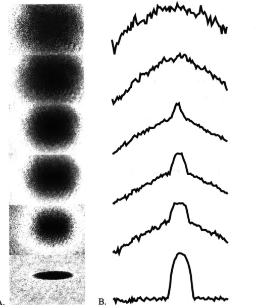
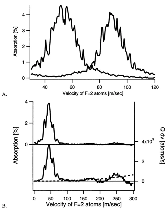
the first evidence seen for BEC was the existence of a bimodal, asymmetric velocity distribution measured in time-of-flight images (see Fig. 2.2). Our first condensates consisted of about 5 million
atoms. By optimizing each cooling phase, we were eventually able to produce condensates of 10 to 25 million atoms, produced at a rate of just over two condensates per minute.
The most critical optimization in the experiment seems to be the polarization gradient cool-ing (see Section 4.3.2). This is optimized by first carefully zerocool-ing magnetic fields by adjustcool-ing currents in a set of three Helmholtz coils, while measuring the magnetic field near the quartz cell with a Hall probe (once the correct currents are established, we have found that the field cancella-tion is stable, and daily adjustment of these currents is not necessary). Then the intensity of each of the counter-propagating molasses beams is carefully balanced. This step involves repeatedly loading the MOT for several seconds, and then switching to dark molasses for several seconds and watching the atoms diffuse away. By observing which way the atoms tend to move in the optical molasses, we can determine which beams are too weak or too strong. Fine readjustment of the beam balance typically has to be done several times during the course of a run. In addition to carefully adjusting beam balance, we have also found that the mode of the beams has to be very smooth in order to get good molasses. Every few days it becomes necessary to clean optics to prevent interference fringes from forming in the beams.
We have found that it is possible to transfer 20 to 30% of the atoms from the MOT to the magnetic trap (only 33% are transfered in the ideal case, since the atoms in the MOT are evenly distributed among three mF spin states, and only one of them is weak-field seeking). Within the first few milliseconds after the magnetic trap is turned on, however, a large fraction of these atoms are lost. This is probably due to the large size of the atom cloud and the proximity of the radial
A. B.
Figure 2.2: BEC transition viewed in time-of-flight. Figure (A) shows a series of time-of-flight absorption images of clouds at various temperatures near the BEC transition. Each picture was taken by evaporating a magnetically trapped cloud of sodium to a different RF frequency (a lower frequency corresponds to a lower temperature-see Section 5.6), and then allowing the cloud to expand ballistically for several milliseconds. The final evaporation frequency for each frame is 2.5, 2.2, 2.15, 2.1, 2.0, and 1.7 MHz (from top to bottom). The appearance of a cold, asymmetrically expanding cloud of atoms as the temperature is lowered is an indication that the BEC transition temperature has been reached. The bottom image shows a nearly pure Bose condensate consisting of 5 million atoms. The time-of-flight for each image was 30 ms, with the exception of the bottom most image for which it was 50 ms, and the width of each frame is 3.2 mm. Figure (B) shows the vertical atom density profile for each frame in figure (A). The presence of a Bose condensate in the four coldest clouds is easily seen in the bimodality of their profile.
instability in the magnetic trap (see Section 5.2). This loss was minimized, but not eliminated,
by adjusting the initial currents used to generate the magnetic trap. After this initial loss, the trap
becomes very stable, decaying with a reasonably long time constant of about 1 minute due to collisions with background gases.
Careful optimization of the rate at which the RF frequency is swept during evaporation has not seemed to make an impact in the size of condensates produced. Some improvement was obtained
by increasing the RF power at the beginning of the evaporation from the values initially used.
Beyond a certain point, however, increasing the power further no longer had an effect. The total RF power requirements are not very high, and when our RF amplifier malfunctioned, we found that we could produce Bose condensates using just the power which was output directly from our digital frequency synthesizer (~ 10 mW).
Due to the high field gradients produced by our magnetic trap, and to the limited frequency of our RF synthesizer (30 MHz), RF evaporation starts off by spin-flipping atoms which are closer to the middle of the cloud rather than at the edge. But when we tried to extend evaporation to higher initial frequencies with the use of a higher frequency RF oscillator, we saw no improvement in the condensate number. After several attempts, we concluded that the initial evaporation was probably limited by the spontaneous evaporation of atoms over the saddle point in the magnetic trap (Section
5.3).
One more important optimization to the experiment is the decompression of the atoms near the end of evaporation. Although decompression was not necessary in our first BEC apparatus, the higher field gradients in our new trap create high enough atom densities in the condensate to make inelastic three-body collisions a significant loss mechanism. As a result, we found that it is beneficial to weaken the trap during the last 250 to 500 ms of evaporation.
Now that the apparatus has been debugged and peaked up, it functions quite reliably. On a reasonably good day the lasers can be warmed up and aligned within three or four hours, after
which the apparatus requires only a minimal amount of re-adjustment throughout the rest of the run, allowing us to concentrate fully on the experiment at hand.
Chapter 3
The Vacuum System
The vacuum system is a very important part of any alkali gas BEC experiment. The vacuum system must be leak tight, sturdy, and bakeable to high temperatures in order to create and maintain the ultra-high vacuum environment necessary for BEC. Care must be taken to assure that the vacuum conductance between the trapping chamber and the vacuum pumps is high, and that the conductance between the trapping chamber and regions of poorer vacuum is low. Also, since the vacuum chamber is the largest single piece of a typical BEC apparatus, the physical size and shape of the vacuum chamber must be designed to accommodate the magnetic coils and optics which surround it. In this chapter, the vacuum requirements for BEC will be discussed, followed by a description of the vacuum system implemented in the new BEC apparatus.
3.1
Vacuum Requirements
During the creation and study of a Bose-Einstein condensate, the atoms must be thermally insulated from the outside world. This is accomplished by holding the atoms in a trap, isolated from any room-temperature walls by a very good vacuum. No type of insulation is ever perfect, however,
and all sources of heating must be understood and controlled.
There are essentially three ways in which the atoms are coupled to the environment: through blackbody radiation, through fluctuations in the magnetic trap, and through collisions with residual gases in the vacuum chamber. Blackbody radiation can be neglected because the scattering of thermal photons occurs at a very low rate (about one photon per ~ 1020 years!). The coupling of thermal energy through the magnetic trap is also negligible. A typical magnetic trap has a resistance of a few ohms and an RC time constant much longer than a microsecond. This results in an RMS thermal (Johnson) noise current of much less than a nanoamp, a trivial current compared to the typical DC currents in the trap of tens or hundreds of amps (current ripple or other "technical" instabilities in the trap current can, however, lead to significant heating - see Appendix C.3.1). Heating due to collisions with background gases, however, can be a severely limiting factor.
Several groups have reported that a background pressure in the low 10-1- mbar range is neces-sary to obtain magnetic trap lifetimes of one minute. This low required pressure is a result of the extremely low temperature necessary for Bose condensation; in a hotter gas, heating due to grazing incidence collisions are less significant and can be neglected. The rate of background collisions per trapped atom can be written as Rbg = nfbgUbgVbg, where nbg and Vbg denote the density and
thermal velocity of the background gas molecules. Assuming a collision rate of 1 per minute, a background pressure of 10-1 mbar, and a background gas temperature near room temperature, we find that the collisional cross-section, gb, is on the order of 10'
A2,
much larger than the length scale of the inter-atomic potentials. This reflects the major contribution of the long-range van der Waals potential and small-angle scattering to the total cross-section. Background collisions are discussed in detail in [64, 65].3.2
Layout of the Apparatus
In order to load the atom trap quickly, a high flux oven must be used. The temperature of the oven, and the regular introduction of contamination into the vacuum each time it is reloaded with sodium, creates a background gas pressure near the oven which is unacceptable for magnetic trapping and evaporative cooling (the pressure near the oven in our new apparatus typically ranges from a few times 10-8 Torr to as high as 10' Torr).
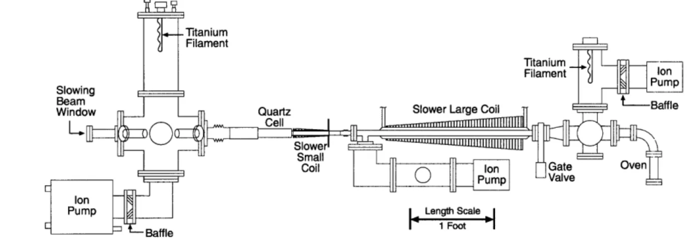
We have gone to great lengths to reconcile the need for a fast loading atom trap with the need for an extreme UHV environment. The result is the vacuum system shown in Fig. 3.1. The vacuum system is segmented into four parts: the oven chamber, the slower, the quartz cell, and the pumping chamber. The narrow, low conductance tubes connecting each part of the vacuum system, and pumps placed in three different places along the chamber assure that the vacuum pressure in the trapping region is about 1500 times lower than the pressure in the oven chamber. A detailed analysis of vacuum conduction in our new apparatus is given in Appendix A.
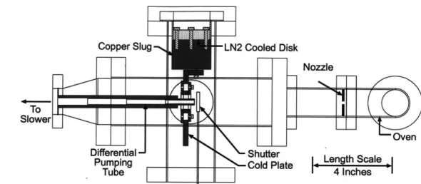
The oven chamber, shown in Fig. 3.2, contains the sodium oven (the source of the sodium beam which loads the trap) as well as the cold plate/differential pumping assembly which collimates the sodium beam and limits the flow of gases between the oven chamber and the slower. The oven chamber is pumped by a 60 liter/second ion pump (protected from alkali poisoning by a water cooled baffle) supplemented by a titanium sublimation pump. In order to isolate the relatively dirty vacuum of the oven chamber from the UHV vacuum of the slower and trapping regions, a nitrogen cooled cold plate and differential pumping tube are employed. The cold plate is a piece of copper which can be cooled with liquid nitrogen to collect hot sodium atoms and other vacuum contaminants. The differential pumping tube, detailed in Fig. 3.3, is a 7" long copper tube connected to the back of the cold plate. The 3/16" diameter opening in the end of the differential pumping tube nearest the oven serves to collimate the sodium beam. The other side of the tube
.Titanium Filament Titanium Filament Ion Slowing P---Beam CBaffle
Window Quarz LagCi rlwe
UJ --- LSlower
Coil Ion Gate Oven
Pump Valve
Ion
eBaffle
Figure 3.1: Side view of the vacuum system. The major gas load in the experiment is produced by the oven (on the far right). The oven, pumped by a 60 liter/second ion pump in combination with a Ti sublimation pump, is separated from the slower by a narrow differential pumping tube (see Figs. 3.2 and 3.3) with a vacuum conductance of just 0.14 liters/second. As a result, background molecules are several thousand times more likely to find themselves stuck in the ion or Ti subli-mation pumps than to enter the slower. The relatively narrow slower tube is pumped on by a 60 liter/second ion pump, adding an additional stage of differential pumping. The trapping region is evacuated through the UHV pumping chamber, pumped on by a 120 liter/second ion pump and a Ti sublimation pump. The result is a vacuum of order 10-" Torr in the quartz cell where the atoms are trapped. A detailed vacuum conduction analysis is contained in Appendix A.
Copper Slug -LN2 Cooled Disk
TO Slower
Differential Shutter
Pumping Cold Plate
Tube Nozzle en
ON
Length Scale _ F4Ices lFigure 3.2: Oven/Cold plate assembly (top view). Sodium escaping through the oven nozzle is col-limated by the end of the differential pumping tube attached to the cold plate. The cold plate is heat sunk to a copper slug which conducts heat out of the vacuum system to a liquid nitrogen cooled disk, allowing the cold plate and the differential pumping tube to be cryogenically cooled. The dif-ferential pumping tube (detailed in Fig. 3.3) has a stepped inner bore to minimize its conductance without clipping the radially expanding sodium beam.
is sealed to the vacuum chamber with a thin stainless steel membrane, such that the only channel between the oven chamber and the slower is through the narrow bore of this tube. This limits the rate at which gas from the oven chamber streams into the slower. The steel membrane was made as thin as possible to lower the heat conduction from the vacuum chamber walls to the nitrogen cooled differential pumping tube.
The inner bore of the differential pumping tube changes in several steps, approximating a cone. This design provides the lowest possible conductance without occluding any part of the conically expanding atomic beam. This is an improvement over the cylindrical tube used in our first experiment, because not only are the atoms which strike the side of the tube lost from the beam, but they also have the tendency to bounce around inside the tube, colliding with other atoms and choking the atomic beam.
Cooling of the cold plate/differential pumping tube assembly is accomplished by conduction
Inner bore 3/8" diameter E F 5/16" 1/4" 3/16" .875"
1
1 1
CD 1.50" 2.00" 2.00" 1.5" 7.00"Figure 3.3: Differential pumping tube.
through a two inch diameter copper slug which protrudes out of the vacuum chamber. This method was chosen over direct liquid nitrogen feedthroughs into the vacuum to allow the possibility of cooling the cold plate with a commercial closed loop chiller. We have found that, unlike our older
BEC apparatus, once the sodium oven has been degassed, liquid nitrogen cooling is not necessary.
This is probably a result of the conically tapered differential pumping tube; since very little sodium strikes the inner walls of this tube, the enhanced sticking coefficient for sodium which cryogenic cooling provides is not necessary to prevent sodium from bouncing around in the tube.
The oven chamber can be isolated from the slower with the gate valve shown in Fig. 3.1. This allows us to vent the oven chamber (to reload the sodium, for example) without losing the ultra-high vacuum in the slower and trapping chambers. The o-ring in the gate valve is made of Kalrez, allowing the valve to be baked to 2500 C. The slower (essentially consisting of a one meter long tube surrounded by magnetic coils) is divided into two parts, as described in Section 4.2.4. A tee placed between the two halves is attached to a 60 liter per second ion pump, providing an additional stage of differential pumping and limiting the flow of gas from the slower into the trapping region. Immediately after the tee is a glass to metal seal to which the quartz cell is attached. The first segment of the cell is a narrow (3/4 inch) quartz tube. The second slower coil is wound around a brass spool surrounding this tube. At the end of the tube, the cell opens up into a square
Formed Graded
0 Bellows Tube Quartz Cell Graded Welded
~Tube Bellows Bellow 'low 000 Glass In Glass to Metal to Metal Seal Seal
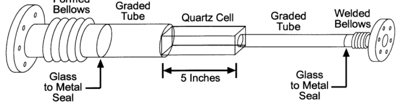
Figure 3.4: The quartz cell. The central part of the quartz cell has a square cross-section, 32 mm on a side. This section is 5 inches long, and is made of four optically flat quartz plates diffusion bonded together. The square section of the cell is connected to round tubes on either side. Both the larger 2" diameter tube and the smaller 3/4" diameter tube are fused to quartz-to-metal seals utilizing graded glass which gradually changes from pure quartz on one side, to a special glass with a thermal expansion coefficient matched to the metal seal on the other. Both glass-to-metal seals are welded to a conflat flange through a bellows to help isolate the fragile cell from mechanical stress.
cross-section. The rectangular part of the cell was made to be 32 mm on a side and 5" long to
accommodate the magnetic trap and allow for the entrance of large MOT beams. At the far end of the trapping region, the quartz cell opens up further into a 2" diameter round tube to optimize vacuum conduction into the pumping chamber. A scale diagram of the quartz cell is given in Fig. 3.4.
It should be noted that while many experiments employ fragile glass cells, very few of them are connected between two large steel chambers. This made the assembly of the vacuum system an extremely delicate process. To lower the risk of breaking the quartz cell, both ends of the cell are connected to the vacuum chamber through vacuum bellows. A stiffer formed-bellows on the large diameter tube provides a small amount of flexibility while the chamber is being assembled. Under vacuum, this bellows is completely compressed, providing a rigid mounting point for the glass cell. The small end of the cell is connected to a very flexible welded-bellows which prevents small amounts of relative motion between the slower and the UHV pumping chamber from cracking the
cell.
When first installing the quartz cell into the vacuum chamber, the cell cracked twice. The cell was then modified by reinforcing its three weakest points. Two of the weak points were the unions between the square section of the cell and the round tubes on either side of it. Since diffusion bonding creates weaker joints than traditional heat fused joints, and since these junctions are a fair distance from the center of the trap, it was possible to have a glass blower strengthen these joints
by fusing them with a torch without destroying the optical quality of the quartz near the center
of the magnetic trap. The third weak point was a molybdenum quartz-to-metal seal. Flexible molybdenum seals allow quartz to be sealed directly to stainless steel, minimizing the length of the 2" diameter tube between the square part of the cell and the UHV pumping chamber. We found, however, that molybdenum seals can be very fragile. This seal was replaced with a quartz-to-metal seal which utilizes a section of graded glass tube, varying across its length from pure quartz on one side to a glass formulated to match the thermal expansion of the metal tube on the other. This length of graded glass tubing added a few inches to the length of the cell, reducing vacuum conduction by a small amount, but resulted in a more durable seal. Since these modifications were made, we have installed the cell twice without problems, and the cell has been in use for over a year now without mishap.
The pumping chamber is a large, many-port chamber to which an ion and titanium sublimation pump are connected. Other ports on this chamber are filled with ion gauges, a residual gas analyzer, and a bakeable all-metal valve (to which a turbo pump can be attached when pumping down and baking out the chamber). The port opposite the quartz cell contains a window to allow the slowing laser beam to enter the apparatus. The window is set off from the chamber with a nipple so that it can be heated (to prevent fogging of the window from the sodium beam) with minimal heat conduction to the rest of the chamber. UHV vacuum is obtained in the new apparatus by pumping on the chamber with a turbo pump while the chamber is baked at 250 C for several days.