Dual Ring Bus Electrical Distribution System for US Navy Destroyer- and Frigate-Sized Vessels
Chathan Cooke, Julie Chalfant, Chryssostomos Chryssostomidis Technical Report MITSG # 12-05
Design Laboratory, MIT Sea Grant College Program December 7, 2012
Topology: Dual Ring Bus
In response to a Request for Information from the Office of Naval Research regarding electrical architectures to be considered in an architecture evaluation study for two candidate hull forms including a 10,000 ton destroyer-sized vessel and a 5,000 ton frigate-sized vessel, the Design Laboratory of the MIT Sea Grant College Program proposes a dual ring bus topology as described in the following.
Brief Topology Description
The dual ring bus topology shown in Figure 1 consists of two separate ring buses: one for propulsion and one for all other loads. The propulsion bus is a short ring that extends from zone 2 through zone 4 and provides power to the propulsion motors. The mission bus runs throughout the length of the ship and provides power to all mission and hotel loads. The small gas turbine generators are connected to the mission bus, and the large gas turbine generators are connected to both the mission and propulsion bus; the amount of power sent to each bus is driven by the load demand. A cross-connect between the buses allows propulsion power to be provided by the small gas turbine generators if no large gas turbine generators are on line.
Each vital load is connected to both the port and starboard sides of the ring. There are redundant power conversion modules for each zone and for each major mission load.
Figure 1: Top Level Block Diagram of Dual Ring Bus Topology for 10,000 ton Threshold Variant Ship
Dual ring with low-voltage bus variant
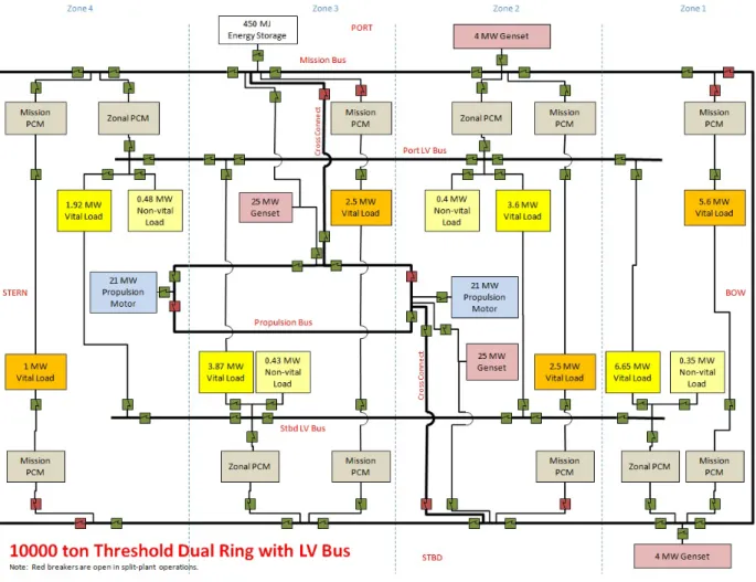
The dual ring bus with low-voltage bus topology, shown in Figure 2, is very similar to the dual ring bus topology described above. The difference is that a low voltage bus runs the length of the ship on both port and starboard sides. Instead of having two zonal power conversion modules in each zone, redundancy is provided through connectivity to the zonal power conversion modules in other zones. Thus, there are four zonal converters instead of eight.
Figure 2: Top Level Block Diagram of Dual Ring Topology with Low Voltage Bus for 10,000 ton Threshold Variant Ship
Architecture Advantages and Disadvantages
The dual ring bus topology reduces the maximum power level on each bus, so that the full installed power of the vessel is not required to be transmitted throughout the ship. This reduces the size of each bus and the breakers or disconnects associated with the main bus, at the expense of adding cable length (an additional bus and the cross connects) and additional breakers or disconnects. Separating the propulsion loads from the mission and hotel loads reduces the complexity of each bus, which improves reliability while maintaining flexibility. Improvements to safety and power transmission issues may be seen as well.
The ring bus topology inherently provides two sources of power to every load (from both forward and aft); this robustness is increased by linking the vital loads to the ring buses on both the port and starboard sides of the ship and providing redundant converters for zonal and mission loads, also on both sides of the ship. The mission bus and redundant converters are separated transversely and vertically for reduced vulnerability. The cross connects between the mission and propulsion buses provide yet another path for power flow.
It would be interesting to investigate the filtering requirements of this topology in more detail. For example, the propulsion bus is connected only to the motors and the two large generators, so it may be possible to allow this bus to operate with reduced filtering since the equipment
connected to the bus might be resilient to harmonics. If this were allowed, the cross connects to the mission bus would need to be filtered. In an ac application, it may be feasible to allow the bus frequency to vary.
Protection/Reconfiguration Philosophy
This topology features a ring configuration for the main distribution bus which provides two alternate feeds for each vital load and each mission load. The ring-tie allows bow and stern cross connects if needed. In addition, the propulsion bus is a ring configuration with cross connects that can bring power in from the mission bus.
All vital loads are connected to the distribution buses via an automatic bus transfer (ABT) that automatically shifts power from one bus to the other in case of loss of power from one side. The control system limits total power drawn from any bus as described in the following section, thus avoiding overloading the remaining operational generator(s).
Control Philosophy
Since the installed power is less than the aggregate total load, the load must be controlled at all times to avoid exceeding the power supply. We recommend a supervisory fully-redundant control system using a concept similar to smart grid technology in which the power distribution is controlled through the control of the load levels. This control system must maintain
essentially real-time status of load demand and power generation, even in the face of disruptions up to and including combat damage. Detailed discussion of the control philosophy in damage scenarios is not addressed herein. When the plant is operated in split-plant mode, the control system manages power for each bus (port and starboard) independently.
For normal operations, all loads except propulsion will be allowed to draw full power; note that this means non-vital loads will be able to draw full power as well. The maximum propulsion load allowed will be limited to the amount of generation capacity on line minus the active mission and hotel load; as equipment is operated, the available maximum propulsion load will fluctuate. The propulsion load may of course take any value less than the maximum allowed at any point in time; in other words, the ship may always go slower than maximum speed available. Operating all loads at maximum power and taking distribution losses into account leaves
approximately 26 MW available for propulsion with all generators on line. Using a speed-power curve for a representative 10000 ton destroyer, 26 MW of propulsion power allows the ship to maintain approximately 25 knots in speed.
An alternative restricted maneuvering mode must be available in which propulsion power takes priority over other loads. In this scenario, the remaining loads must be prioritized and limits set that allow full propulsion power.
During an emergent event such as a fault or other casualty, non-vital loads will be shed; however, non-vital loads are only 3% of the installed power, so shedding these loads will have little impact on overall powering and further action must be taken. Propulsion power will be limited, and a scenario must be developed to potentially limit other loads as required. Examples could include limiting repetition rate for pulse weapon firing or instantiating a lower power mode for radar operations.
An additional consideration is that a minimum allowable propulsion upper limit must be in place to allow the ship to maintain steerageway. This minimum upper limit could come into play in casualty events, but also during operations with less than maximum power on line.
Concept of Operations
1. Battle Condition. The ship operating in battle condition will have all generators running and on line in a split plant configuration. This configuration will be achieved by opening breakers forward and aft on both the propulsion and mission buses such that the port side motors and generators and the zonal and mission loads in zones 2 and 4 are connected to the port bus and the remaining equipment is connected to the starboard bus. The breakers that would be open in this configuration are colored red in the top level block diagram. 2. Single Generator Operations. The energy storage module has sufficient capacity to
provide 2.5 MW of power for 3 minutes, which should be sufficient time to start a standby generator, even allowing for a misfire. Therefore, single generator operations will be allowed when the ship is in a threat-free environment. For single generator operations, all breakers are closed in both the ring and mission buses. Assuming the single generator is one of the main generators, the breakers in the cross connects will be open as the generator will be connected to both buses simultaneously.
Implementation details
Medium voltage dc implementation details:
In the medium-voltage dc version, power is generated as variable frequency ac using high-speed generators operating at the most economical speed for the load. Power is rectified at the source and is distributed throughout the ship at 9.3 kVdc. The propulsion motor drives and the pulse weapon are powered via a variable frequency ac drive which can accept dc bus voltage without conversion. The remaining major mission loads require a 1 kVdc voltage input, so a dc-dc converter is required for each major load. We assume that all in-zone loads are 450Vac 60 Hz, so the power is transformed and inverted at the entry to each zone, then distributed individually to each in-zone load at 450 Vac 60 Hz.
All switches on the dc side of the bus are dc disconnects; when power must be interrupted, power flow is controlled through the associated power electronics equipment and the disconnect is used for isolation. AC breakers are provided within the ac portions of the distribution system and between the generators and associated rectifiers.
Medium voltage 240 Hz. ac implementation details:
Power is generated at 240 Hz ac using high-speed generators and is distributed throughout the ship at 6.9 kV. The major mission loads and propulsion motor drives require a dc voltage input, so power is transformed and rectified for each major load. We assume that all in-zone loads are 450Vac 60 Hz, so the power is converted and transformed at the entry to each zone.
Medium voltage 60 Hz. ac implementation details:
Power is generated at 60 Hz ac using conventional generators and is distributed throughout the ship at 6.9 kV. The major mission loads and propulsion motor drives require a dc voltage input, so power is rectified for each major load. We assume that all in-zone loads are 450Vac 60 Hz, so the power is transformed at the entry to each zone.
Ship variant details:
Top-level block diagrams and detailed equipment lists for all variants are included below. In addition, detailed one-line diagrams of the 10,000 ton threshold variant in MVDC, HFAC and MVAC are provided.
Acknowledgments
This work is supported by the Office of Naval Research N00014-08-1-0080, ESRDC Consortium, and MIT Sea Grant College Program under NOAA Grant Number NA06OAR4170019, MIT SG Project Number 2008-ESRDC-01-LEV.