HAL Id: hal-00592712
https://hal.archives-ouvertes.fr/hal-00592712
Submitted on 3 May 2011HAL is a multi-disciplinary open access archive for the deposit and dissemination of sci-entific research documents, whether they are pub-lished or not. The documents may come from teaching and research institutions in France or abroad, or from public or private research centers.
L’archive ouverte pluridisciplinaire HAL, est destinée au dépôt et à la diffusion de documents scientifiques de niveau recherche, publiés ou non, émanant des établissements d’enseignement et de recherche français ou étrangers, des laboratoires publics ou privés.
Impacts de projectiles déformables sur des dalles minces
en béton armé : essais, modélisation, simulations
Christophe Pontiroli, Alain Rouquand
To cite this version:
Christophe Pontiroli, Alain Rouquand. Impacts de projectiles déformables sur des dalles minces en béton armé : essais, modélisation, simulations. 10e colloque national en calcul des structures, May 2011, Giens, France. pp.Clé USB. �hal-00592712�
CSMA 2011
10e Colloque National en Calcul des Structures 9-13 mai 2011, Presqu’île de Giens (Var)
Soft Projectile Impacts on Thin Reinforced Concrete Slabs : Tests,
Modelling and Simulations
C. Pontiroli1, A. Rouquand1 1
CEA, DAM Gramat, ,F-46500 Gramat, France, christophe.pontiroli@cea.fr 1CEA, DAM Gramat, ,F-46500 Gramat, France, alain.rouquand@cea.fr
Abstract — Numerical simulations of reinforced concrete structures subjected to high velocity impacts and explosions remain a difficult task today. These difficulties are related to numerical aspects, but also due to the ability of the material model to simulate the accurately behaviour of a very complex and heterogeneous material like concrete. A new concrete model, named PRM model, has been developed at CEA-Gramat (Pontiroli, Rouquand & Mazars [1], [2], [3]) to predict the concrete response under a large range of dynamic loadings.
Keywords — Impact, experiment, concrete model, simulation
1.
Introduction
Works presented in this paper have been performed in the framework of the French VULCAIN PGCU 2007 research project (founded by the French National Research Agency). This project aims at defining a theoretical and probabilistic methodology in order to assess the structural safety of industrial structures that might be submitted to transient loadings such as blasts or impacts generated by various projectiles. A complementary objective is to improve diagnosis, prevention or protection actions. This scientific program gathers well-known and complementary scientific institutes, firms and universities in France.
2.
Impacts tests
CEA-Gramat has carried out impact tests on reinforced concrete slabs with deformable projectiles to get experimental data to validate numerical tools developed in VULCAIN project.
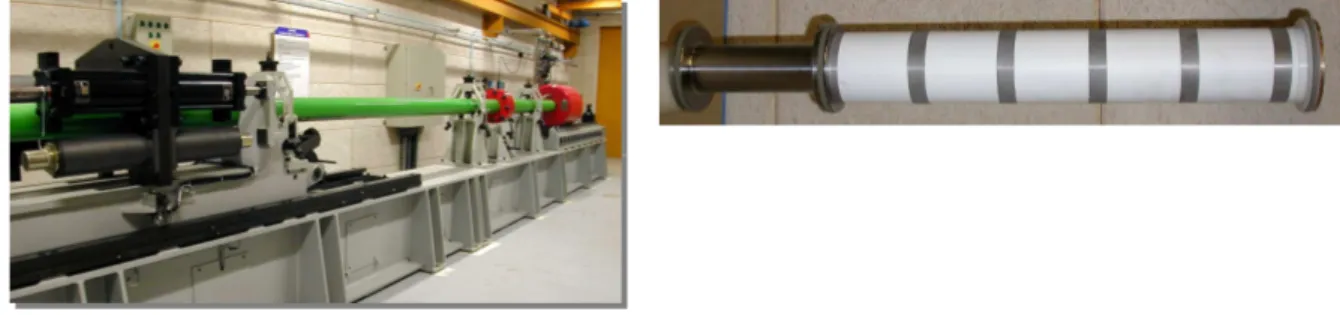
A steel cylindrical projectile with sections of different thickness has been launched on the target by a gas gun with 90 mm calibre (Fig. 1). Front part of projectile is composed of a thin steel S235 tube
Φ=80 mm, L=500 mm). This tube has a thickness of 1 mm on the front 250 mm long section and a thickness of 2 mm on the remaining 250 mm long rear section. Rear part of projectile is composed of a massive steel 35NCD16 cylinder designed to mount an acceleration recorder system inside the projectile to measure the axial acceleration during the tests.
Fig. 1: Gas launcher and deformable projectile (about 5 kg)
Reinforced concrete slabs 2 m long, 1.2 m large and 7 cm thick have been used as targets to simulate soft projectile impact. The projectile velocity is changed in order to get different damage levels going from simple bending to full perforation.
A standard concrete mixture named R30A7, defined several years ago by CEA-Gramat and Laboratory 3SR at Grenoble, is used with an amount of 1.0 vol. % steel reinforcement (Φ= 6 mm S235 steel rebar with 80x80 mm2 square grid). The tested R30A7 concrete displays a 28-day compressive strength of 30 MPa and a slump of 7 cm. It should be noted that a very high-quality cement is used. This high quality gives better material reproducibility and leads to a particularly low cement volume. Aggregate compounds, with a maximum size of 8 mm, containing 99% of quartzite, are derived from natural deposits (rolled aggregates, 99% quartzite).
Target is held tight by a metallic support which is supposed to be perfectly rigid. Video cameras and displacement sensors located on the rear face of the slab complete the measurements.
Nine tests have been performed with different impact velocities going from 70 to 135 m/s. In this paper we present two experimental results obtained for velocities of 107.5 m/s (test n°1) and 70.2 m/s (test n°2).
In the first test we have obtained perforation of the reinforced concrete slab with a projectile residual velocity of about 46.6 m/s. A series of plies are formed on the steel tube during the projectile crash process and the first cylinder part with a thin wall thickness of 1 mm is completely buckled (Fig. 2).
Fig. 2: Deformation of the missile after perforation (test n°1, V0 = 107.5 m/s)
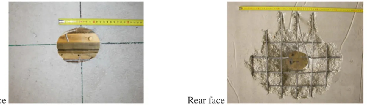
Fig. 3 shows the damage obtained on the front and rear sides of the reinforced concrete target. We can observe on the one hand the formation of a plugging cone with an important scabbing effect on the rear face, and on the other hand the failure of several steel rebars.
Front face Rear face
Fig. 3: Damage of the reinforced concrete slab after test n°1 (V0 = 107.5 m/s)
In the second test presented here, perforation has not been completed and a rebound of the projectile has been observed. A series of plies are formed on the steel tube during the projectile crash process and the first cylinder part with a thin wall thickness of 1 mm is buckled on a length of 150 mm long (Fig. 4).
Fig. 4: Deformation of the missile after perforation (test n°2, V0 = 70.2 m/s)
Fig. 5 shows the damage obtained on the front and rear sides of the reinforced concrete target. We can observe scabbing effects and the formation of a plugging cone, but the failure of steel reinforcement is not reached. Hence, in test 2, the kinetic energy of the projectile isn’t sufficient to perforate the reinforced concrete slab.
Front face Rear face
Fig. 5: Damage on reinforced concrete slab after test n°2, V0 = 70.2 m/s
3.
Damage and plastic model for concrete : PRM Model
These tests have been simulated using the finite element method and a specific concrete material model. A damage model has been developed at CEA-Gramat to simulate the behaviour of concrete under severe loading [1], [2], [3]. This model includes two scalar damage variables that give respectively the loss of stiffness under tensile loading and the loss of stiffness under compressive loading (see Fig. 6). The damage evolution laws are controlled by an equivalent tensile strain.
Fig. 6: Stress strain curve for a tensile - compressive loading
σ ε Tension Compression σc σt
Strain rate effects are introduced to model the increase of the maximum tensile and compressive strengths observed under moderate and high strain rate loading. Experimental data have been obtained on R30A7 concrete using the Hopkinson bar facility at laboratory LPMM of Metz and using an impulsive electromagnetic pressure generator device (GEPI) at CEA-Gramat (see Fig. 7).
Fig. 7 : Experimental Strain rate effects obtained on the R30A7 concrete [4]
The Hillerborg regularization concept [5] has been applied to limit mesh dependency during strain and damage localization phenomena. A frictional stress is also added to simulate hysteresis loops during unloading and reloading paths. These frictional stresses introduce internal damping forces which are frequency independent but are related to damage parameters and then to tensile cracking phenomena.
Under high pressure regime in porous material, irreversible volumic strain can be observed like compaction, as well as confined shear yielding, those mechanisms can drive a significant part of the material response. In order to take into account all these phenomena, the plastic Krieg model has been coupled to the PRM damage model [2]. We haven’t activated this plasticity part of the PRM model to simulate impact tests carried out at CEA-Gramat. In these experiments the damage drives the concrete response and confinement pressure isn’t sufficient to play a significant part in the concrete behaviour. The PRM model is available as a user subroutine (VUMAT) in the ABAQUS explicit finite element code. It is compatible with almost all the finite element library (1D truss elements, beam elements, 2D plane strain and plane stress elements, 2D axisymmetric elements, 3D solid elements).
4.
Numerical simulations
Numerical simulations of this problem are not easy because there are strong interactions between the target behaviour and the projectile crash process. Accurate predictions require a proper modelling of both the target and the missile response. In order to evaluate the capabilities of the explicit finite element code Abaqus including the PRM model, 3-D numerical simulations of CEA-Gramat impact tests have been conducted. The objective is to determine the capabilities and the limits of such simulations.
A 3-D finite element model with solid brick elements has been used for the target (60 000 eight nodes solid elements) and the reinforcement is explicitly modelled using 2 nodes beam elements with a circular cross section (3 342 elements). Reinforcement elements are embedded in the concrete finite element mesh. Two symmetry planes are used and only a quarter of the plate and of the projectile is modelled. Concrete nodes are not coincident with the reinforcement nodes but a displacement constraint is applied on these nodes in order to simulate a perfect adherence between steel and
concrete. The projectile is composed of a thin steel tube which is efficiently modelled using 3-D shell elements (1 568 elements). The behaviour of the metallic parts of the structure, the steel reinforcement and the metallic projectile tube are simulated using the Johnson Cook dynamic failure model [6]. Fig. 8 shows the projectile/target interaction at 2.5 and 10 ms during test n°1. We can observe scabbing phenomena, the formation of a concrete plugging cone and the failure of the reinforcement during the projectile penetration phase. Computed failure mechanisms appear in very good agreement with the experimental observations. On Fig. 9, the projectile velocity obtained during the test (calculated by integration of the accelerometer signal) is compared to the numerical velocity. The simulated velocity profile matches accurately the experimental data, especially the residual velocity at the end of the perforation process. On this figure, we observe also the projectile shape at the end of the numerical simulation (to compare with Fig. 2).
Fig. 8 : Numerical simulations results obtained at 2.5 and 10 ms (test n°1, V0 = 107.5 m/s)
0 20 40 60 80 100 120 0 1 2 3 4 5 6 7 8 Time (ms) V e lo c it y ( m /s ) Experiment Simulation
Fig. 9 : Test 1: Evolution of the projectile velocity and projectile shape (test n°1, V0 = 107.5 m/s).
On Fig. 10, we compare the numerical and the measured projectile velocities obtained in test n°2. The numerical simulation is able to reproduce the missile deceleration and the rebound at the end of the impact process. On this figure, we observe also the projectile shape at the end of the numerical simulation (to compare with Fig. 4).
Fig. 11 shows the computed deformed shape of the front and rear faces of the target at the end of the numerical simulation (at 200 ms). The contours plotted on the reinforced concrete target give the maximum values reached by the principal tensile strains. The blue contours correspond to concrete surface damaged by the yielding process of rebars. Numerical results show that the reinforcement doesn’t fail (like in the experiment) but formation of plugging cone is initiated on the rear face of the reinforced concrete plate (like in the experiment – see Fig. 5).
Fig. 12 shows the displacement histories of the two points DV2 and DV4 located on the rear face of the reinforced concrete plate. A good agreement is observed between experiment and simulation concerning maximum displacements, although damping is under-predicted in the computation. Frictional effects between the reinforced concrete slab and the supports may explain such phenomena.
-20 0 20 40 60 80 0 1 2 3 4 5 6 7 8 Time (ms) V e lo c it y ( m /s ) Experiment Simulation
Fig. 10 : Test 2: Evolution of the projectile velocity and projectile shape (test n°2, V0 = 70.2 m/s)
Front face Rear face
Fig. 11: Test 2: View of the maximum principal tensile strains reached on the reinforced concrete target during the impact (test n°2, V0 = 70.2 m/s)
-20 -15 -10 -5 0 5 10 15 20 25 0 20 40 60 80 100 120 140 160 180 200 Time (ms) D is p la c e m e n t (m m ) DV2 Experiment DV4 Experiment DV2 Simulation DV4 Simulation
Fig. 12 : Measured and computed displacements at points DV2 and DV4 (test n°2, V0 = 70.2 m/s)
5.
Conclusions
Configurations of soft projectile impact on thin slabs presented in this paper demonstrate the efficiency of the proposed explicit finite element procedure to capture the real behaviour of reinforced concrete structure and projectile (displacements, damaged areas, crack pattern, plugging and scabbing on reinforced concrete slab - velocity and residual shape of the projectile).
Results show the capabilities of the PRM model to reproduce accurately on the one hand the bending response of the reinforced concrete slab, and on the other hand the concrete failure mode due
DV4 DV2 L: 2 m H: 1m20 60 cm 33 cm 33 cm
to the projectile perforation. This model can advantageously help to predict the vulnerability of reinforced concrete structures to impact problems.
Acknowledgements
This research program has been performed with the financial support of the French ministry of defence (DGA). The French National Research Agency (ANR PGCU 2007) and Laboratory 3SR at Grenoble are also gratefully acknowledged.
References
[1] C. Pontiroli, 1995, “Comportement au souffle de structures en béton armé, analyse expérimentale et modélisation”, thèse de doctorat, Ecole Normale Supérieure de Cachan, Centre d'études de Gramat.
[2] A. Rouquand, 2005, “Presentation d’un modele de comportement des geomateriaux, applications au calcul de structures et aux effets des armes conventionnelles”, Centre d'Etudes de Gramat, rapport technique T2005-00021/CEG/NC.
[3] Mazars J., 1984. “Application de la mécanique de l’endommagement au comportement non-linéaire et à la rupture du béton de structure”. Thèse d’état de l’Université Paris VI, France. [in French]
[4] Erzar B., Forquin P., Buzaud E., Pontiroli C. “Tensile strength of mortar over a wide range of strain rate”, DYMAT2009, Bruxelles, Proceedings
[5] Hillerborg A., Modeer M., Petersson P. E., 1976, “Analysis of crack formation and growth in concrete beams of fracture mechanics and finite elements”, Cement and Concrete Research, Vol. 6, pp 773-782.
[6] Johnson G. R. and Cook W. H., “Fracture characteristics of three metals subjected to various strains, strain rates, Temperatures and pressures”, Engineering Fracture Mechanics, vol. 21, n° 1 PP 31-48, 1985

![Fig. 7 : Experimental Strain rate effects obtained on the R30A7 concrete [4]](https://thumb-eu.123doks.com/thumbv2/123doknet/12880619.369992/5.892.283.634.249.471/fig-experimental-strain-rate-effects-obtained-r-concrete.webp)


