HAL Id: hal-02263430
https://hal.archives-ouvertes.fr/hal-02263430
Submitted on 4 Aug 2019
HAL is a multi-disciplinary open access
archive for the deposit and dissemination of
sci-entific research documents, whether they are
pub-lished or not. The documents may come from
teaching and research institutions in France or
abroad, or from public or private research centers.
L’archive ouverte pluridisciplinaire HAL, est
destinée au dépôt et à la diffusion de documents
scientifiques de niveau recherche, publiés ou non,
émanant des établissements d’enseignement et de
recherche français ou étrangers, des laboratoires
publics ou privés.
The product line engineering approach in a
model-driven process
H Dubois, V. Ibanez, C. Lopez, Joseph Machrouh, N Meledo, P. Mouy, A.
Silva
To cite this version:
H Dubois, V. Ibanez, C. Lopez, Joseph Machrouh, N Meledo, et al.. The product line engineering
approach in a model-driven process. Embedded Real Time Software and Systems (ERTS2012), Feb
2012, Toulouse, France. �hal-02263430�
The product line engineering approach in a model-driven process
H. Dubois
1, V. Ibanez
2, C. Lopez
3, J. Machrouh
4,
N. Meledo
2, P. Mouy
1, A. Silva
51
: CEA LIST, Boîte Courrier 94, 91191 Gif-sur-Yvette Cedex, France 2
: THALES AVIONICS, 3, Rue Toussaint Catros, 33187 Le Haillan Cedex, France 3
: Tecnalia, Parque Tecnológico de Bizkaia, E.202, 48170 Zamudio, Spain 4
: THALES R&T, Campus Polytechnique, 1 avenue Augustin Fresnel, 91767 Palaiseau Cedex, France 5
: Fraunhofer IESE, Fraunhofer-Platz 1, 67663 Kaiserslautern, Germany
{[email protected], [email protected], [email protected], [email protected],
[email protected], [email protected], [email protected]}
Abstract: The European CESAR1
Keywords: model-based methodology, product line
engineering, requirements, system architecture, variability management.
project intends to provide industrial companies with a customizable systems engineering platform (a Reference Technologic Platform) that can be used across several application domains (aeronautics, automotive, industrial automation, railway, and space). This paper focuses on the work performed in the aeronautics domain and presents an innovative tooled-up approach for product line engineering used in the Thales Avionics use case. This approach implements the automatic generation of product models from variability models with the guaranty of a requirements database. Domain engineering is here developed in a model-driven process.
1. Motivation
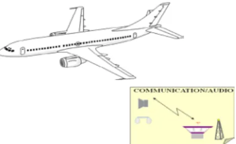
In the world of avionics, depending on the mission, it should be possible to communicate in continental area, in remote and in oceanic area. In order to perform this communication, several types of media are used (VHF for continental area, HF and satellite communication for remote and oceanic area). In an aircraft, communication is divided into three main parts: tuning of radio equipment, voice exchange via reception and signal transmission, and audio management in the cockpit area. These functionalities evolve depending on the use case chosen for the mission (see Figure 1).
The goal of this study is to manage these radio management variabilities according to the different use cases. We want to automate as much as possible the generation of the models of the final product with respect to the initial requirements of the selected variant. Code generation is not considered here.
1 See CESAR website: http://www.cesarproject.eu
Figure 1: Radio management use case
In order to achieve this goal, we introduce in the following sections a method that combines model-driven development with product line engineering. First, we present a brief overview of the approach; then the more specific aspects (domain definition, consistency management between models and requirements, and, finally, variability management). For each step, we briefly introduce tools. In the third section, we then describe the application of the proposed methodology on the industrial use case using the various tools selected before. The last section summarizes the experiment conclusions and gives some recommendations for future work.
2. The proposed methodology 2.1 General process
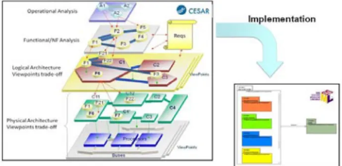
Figure 2 shows the process used to perform this study. It is based on product line engineering and is divided into two main phases: domain engineering and application engineering. In the first phase, the domain engineer performs consistency management between the models and the requirements database and also defines the variability model and the corresponding association with the domain models. Then, during the application engineering phase, the application engineer resolves the variability model, according to the use case and, with tool support, generates the corresponding requirements and models for the final product.
Figure 2: Process workflow
2.2 A specific metamodel
First of all, we have to define the domain model that will be considered here. We base our approach on the MaxSysML domain model defined in the CESAR project [3], where concepts and relations are defined. The purpose of MaxSysML is to propose a dedicated and integrated language for system design adapted to the CESAR platform with common aspects shared by all application domains.
The MaxSysML approach considers different steps that span the system architecture design; MaxSysML also describes the relations between these steps:
• Operational analysis: focus on customers’ needs.
• Functional and non-functional needs analysis: focus on the system itself (behavior, safety…).
• Logical architecture analysis: identification of the system’s components (roles, relationships, properties).
• Physical architecture analysis: similar to logical architecture analysis, but allocated to components.
The MaxSysML metamodel has been implemented as a Domain Specific Language (DSL) in the Papyrus MDT2
The implementation, as illustrated in Figure 2, is done using the technique of UML enhancement with profile mechanism [12], and, more specifically in this case, as a SysML profile [10]. This profile implements the different elements that compose the operational view, the functional analysis, the logical architecture, and the physical level.
tool. Figure 3 illustrates the integration of the CESAR conceptual metamodel as a SysML profile into the Papyrus tool.
2 See: http://wiki.eclipse.org/MDT/Papyrus
Figure 3: MaxSysML DSL as a SysML profile
With respect to the functionalities of Papyrus MDT, an adaptation of the standard UML and the SysML modeling environment is possible when selecting the SysML template that initiates a new model conforming to the MaxSysML DSL. This adaptation covers specific modeling facilities (palette, preferences for manipulated elements, visual enhancements) that are covered by the proposed Eclipse-based Papyrus MDT modeling environment.
2.3 Consistency management
Figure 4: Consistency management
As shown in Figure 4, the model is statically analyzed to extract the data functions and generate an ontology. This step is currently performed manually as its automation was not the principal objective of our cooperation; however, it could be easily automated. The ontology, its associated boilerplate, and the requirements are used as inputs for DODT [8], a boilerplate and ontology handling tool. It is used to check the consistency of the ontology by identifying discrepancies and/or ambiguities with the requirements expressed in DOORS3
3 See IBM Rational DOORS,
. If ambiguities exist, the user has to specify the respective issues. The requirements are updated with this additional information and boilerplate, and then a new consistency checking is done. This
process is iterated until complete verification has been accomplished.
2.4 Variability management
Since radio communication systems have a strong degree of commonality, we use product line engineering to take advantage of this and reuse the already defined requirements and functional decomposition, as well as the consistency checking, as much as possible. The idea is to perform these analyses just once and to be able to generate the appropriate requirements and models for each different mission automatically.
To do so, we rely on variability management tools, which allow us to manage variability in different artifacts used throughout the development. Some tools offer better integration with development tools, while others still lack such support, but are still helpful, as they help us to identify dependencies among variabilities.
Various variability management tools are available. Some of them are based on the feature diagram approach [6, 9] in which the feature model is the central node around which the different product line models are designed throughout the whole product life cycle. There also exist some other approaches [2, 4, 13, and 14] that propose to directly identify variable elements in architecture or behavioral models of the product line to address what is called cross-sectional variability.
Within the CESAR project, three tools for managing variability have been defined/extended. Their integration into development tools, however, is an on-going task, whereas commercial tools enable integration into several tools used for embedded system development (such as IBM DOORS or Papyrus MDT). In particular, pure::variants4
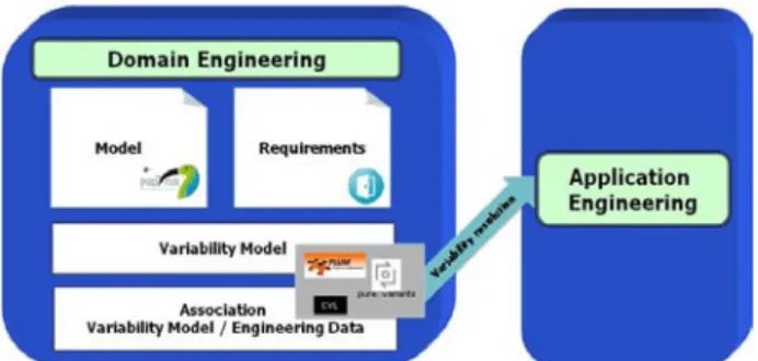
In our case study (see Figure 5), we tested the usage of both commercial and non-commercial tools. pure::variants was used to manage variability in both requirements and functional decomposition models. The other tools used, which are being developed in the CESAR project, were the PLUM and CVL tools.
allows managing variabilities in requirements and design documents, which are issues of interest to us.
4 See pure-systems Website: http://www.pure-systems.com
Figure 5: Variability management
3. Application to case study
In this section, we describe the usage of the different techniques and related tools in the radio management use case. This description concerns the consistency of the ontology, requirements management, as well as the modeling and generation of product-specific models based on the domain models.
3.1 Domain ontology consistency
For this task, the usage of DODT allows the user to directly connect to the DOORS requirements library from which the requirements database is uploaded. The DODT tool automatically launches DOORS when starting. Three inputs are needed: a set of requirements (taken from the DOORS tool); a set of boilerplates expressed in a dedicated file that is uploaded in the tool, and a domain ontology that can be expressed in a Papyrus modeling formalism by using variables. Once these different elements are launched, the DODT offers different functionalities to the user. These functionalities can be listed in two subgroups as illustrated in Figure 6:
1. Editing functionalities. The user can edit the requirements, the boilerplates, and the ontology; the DODT tool guarantees the consistency of data shared between tools (DOORS and Papyrus here).
2. Validation functionalities for requirements analysis. Several types of analyses are available in the DODT tool:
2.1. “Completeness” of the requirements with respect to concepts available in the ontology that are not related to any requirement;
2.2. Detection of “inconsistency” between pairs of requirements;
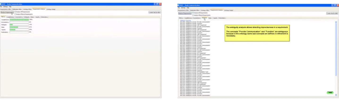
2.3. “Ambiguity” analysis (cf. Figure 7a), which detects inaccuracy of a requirement w.r.t. a related concept of a given requirement which may be refined in the ontology;
2.4. “Noise” detection, which detects requirements in which concepts are not declared in the ontology;
2.5. “Opacity” analysis, which detects the usage of unrelated concepts in the same requirement;
2.6. “Redundancy” for duplicated requirements. A summary of these different metrics is given for the complete set of requirements as illustrated in Figure 7b.
Usage of the DODT tool allows the engineer to get complete traceability between the concepts of the domain and the requirements it manages.
Let us now describe in detail how the models are defined (the models that are also used as input for DODT).
3.2 System models
System models are defined in the Papyrus tool modeling environment. Models are defined as SysML models using the MaxSysML profile defined in the CESAR project. MaxSysML is a SysML profile (as illustrated in Figure 8).
Figure 6: DODT - Inputs and functionalities
Figure 7: DODT - Requirements analysis functionalities: metrics (7a) and ambiguity detection (7b)
Editing commands Analysis commands
Boilerplate selection
Requirement edition w.r.t. ontology inputs
Figure 8: Papyrus - MaxSysML is a SysML profile
This profile extends the Block SysML definition by defining two kinds of elements: LogicalContext and LogicalComponent. FlowPort may be associated with these elements (extension of a SysML FlowPort with the dedicated stereotype).
MaxSysML integrates elements for each of these phases of model-based design of complex systems. For instance, let us consider the MaxSysML definition for logical analysis (cf. Figure 9).
Figure 9: Papyrus - MaxSysML logical analysis
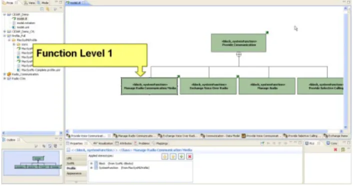
The MaxSysML profile has been developed and implemented in the Papyrus MDT tool with dedicated modeling facilities, including a specific modeling environment with a MaxSysML palette, etc. An example of a functional view of the radio use case can be seen in Figure 10. The elements are defined as MaxSysML elements (with their related stereotypes).
Figure 10: Papyrus MDT modeling with MaxSysML profile
It is structured into several packages that define dedicated modeling elements for operational analysis, system analysis (or functional analysis), logical analysis, physical analysis, and architecture definition.
Next, we present the definition of variability models by the different tools that were tested for this case study and their relations with the system models and with the requirements.
3.3 Variability modeling with PLUM
Let us first consider the usage of PLUM5
A decision model in PLUM is implemented as illustrated in Figure 11. We define functional variability and actions (called validity actions) related to these variability points. Related operational variability questions are associated with these decision nodes.
[1]. PLUM was used for managing variability in requirements. The principle in PLUM is as follows: During the domain engineering phase, we build a decision model that maps decisions to requirements. Then, during the application engineering phase, a resolution model is defined by answering the questions associated with the decisions, which leads to a set of requirements associated with the variant.
Figure 11: PLUM - Decision Model
The mapping between the requirements and a decision model is done by manually defining a set of requirements that are associated with a decision node (identified by the related identifier in the decision model), which is selected in a specific workflow that the user must define. This is done in an XML file created by the user as illustrated in Figure 12.
Figure 12: PLUM - Mapping between requirements and decision model
Then, we define a resolution model as illustrated in Figure 13. In this model, the user makes a selection regarding the different variation points defined in the decision model previously defined.
Figure 13: PLUM - Resolution model
Finally, to generate the variant, we execute the workflow w.r.t. this resolution model on the decision model. A set of requirements that refer to the current variant is then created in a dedicated XML file.
3.4 Variability modeling with CVL
The CVL6
Since CVL uses a different approach, we first explain its usage. The principle of CVL is to start from the complete design of the system (as previously presented in Papyrus with functional decomposition and data flow diagrams), then to define variability in terms of variants that the system could not support and, finally, to produce the system with the selected features (those that were not deleted). We illustrate this usage on the use case.
tool has been used to manage variabilities in data function models.
The variability model can be expressed as a tree as represented in Figure 14.
6 See CVL website: http://www.omgwiki.org/variability/
doku.php?id=cvl_tool_from_sintef
Figure 14: CVL - Variability Feature Model
This tree can also be seen as a model (cf. Figure 15) in which we represent what we do not want to have in the variant to be produced (a subtractive variant w.r.t. the complete solution).
Figure 15: CVL - Diagram for Variability Models
This model is built as follows: We define new variants as models generated from variability expressions. Variability is expressed as a fragment substitution, where the elements of the base model contained in a placement fragment (the user selects the modeling elements in the model view of the Papyrus MDT model – Figure 16) will be replaced by those contained in the replacement fragment (the replacement fragment is an empty fragment here, since we delete variability fragments from the complete solution).
The result is represented in Figure 17, where the complete model is shown on the right-hand side and the variant automatically generated with CVL from the selected fragment is depicted on the left-hand side. Elements present in the complete model disappear in the variant solution.
Figure 17: CVL - Generation of the variant
3.5 Variability modeling with pure::variants
Finally, the usage of the commercial tool pure::variants is evaluated in this context. pure::variants is used as follows: We must first define a feature model, then family models of the system on the one side and of the requirements on the other side. The variant is then generated with the respective list of fulfilled requirements and the related Papyrus model.
Just as in the previous approaches, we start by defining the variant model as a feature model implemented in pure::variants. See Figure 18 for an illustration on the use case.
Figure 18: pure::variants - Feature model
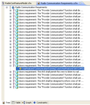
The requirements are then imported from the DOORS tool. The requirements can be associated with the feature model previously defined as illustrated in Figure 19.
Figure 19: pure::variants - requirements and feature model.
A family model contains rules that associate elements of the feature model with elements in the Papyrus model. This is illustrated in Figure 20, where we can see that model elements can be selected (and others not selected) depending on their association with a given feature from the decision model. The selected elements are highlighted in the diagram view.
Figure 20: pure::variants - System models and feature model
A variant can be generated from a feature model as illustrated in Figure 21.
Figure 21: pure::variants - decision model
This feature model can now be used to produce the final models for: 1) the related requirements and 2) their related model. The requirements are generated as illustrated in Figure 22 and can be uploaded to a new DOORS file.
Figure 22: pure::variants - generated requirements
Related to these requirements associated with the generated variant, a dedicated Papyrus model is produced as illustrated in Figure 23. This model can be automatically produced as a UML file, which will contain only those modeling elements that fit with the choices made in the decision model.
Figure 23: pure::variants - generated model
The pure::variants tool offers strong coupling with requirements management using DOORS and with system modeling using the Papyrus tool.
4. Conclusion
The CESAR solutions are a promising asset for embedded systems development in the field of intelligent transportation systems, where there is a huge margin for improvement of development processes. Among the several solutions that are developed within the CESAR project, our approach offers methods and tools for developing domain models with respect to a requirements database in order to ensure conformity between the boilerplate representation of these requirements and the models, and to ultimately generate a product from product line models automatically. All these approaches have been implemented and illustrated in the context of a radio management use case proposed by Thales Avionics.
This experiment used many tools included in the Reference Technology Platform (RTP) of the CESAR project. The commercial tool pure::variants (not included in the RTP) was also tested in this experimentation. This approach is also compliant with a common meta-model (called MaxSysML) for system modeling used within CESAR. This system model, like the requirements database, is shared by different tools; the product line process uses these databases and modifies them while guarantying their integrity. Consistency is ensured between the system models and requirements database by using the ontology (with DODT). Many functionalities are included in these tools; however, the effort needed to connect them to other artifacts varies from tool to tool.
Despite this promising tool chain for product line engineering, some effort is still needed to help end users develop real applications. The major issue is support for the graphical layout of variability models rather than only for the structural layout. Some verification rules also have to be developed to check the consistency and the completeness of the generated models with variability tools. A unique feature model for requirements and model variability would be more convenient for widespread usage. For ontology management, automatic initialization from the models would also be interesting.
Acknowledgements
The research leading to these results has received funding from the ARTEMIS Joint Undertaking under grant agreement n°100016 and from French, German and Spanish national programs and funding authorities.
5. References
[1] Aldazabal A. and Erofeev S. Product Line
Unified Modeller (PLUM). Eclipse Summit
Europe 2007, October 10-11, Ludwigsburg, Germany.
[2] Atkinson C., Bayer J., Bunse C., Kamsties E., Laitenberger O., Laqua R., Muthig D., Paech B., Wust J., and Zettel J., Component-Based
Product Line Engineering with UML,
Addison-Wesley Professional, 2001.
[3] CESAR Deliverable D_SP3_R2.2_M2,
Architecture modeling methodology for RTP V2.
2011.
[4] Clauss M., Modeling variability with UML, GCSE 2001 Young researchers Workshop, 2001. [5] Clements P. and L. Northrop. Software product
lines: practices and patterns, Addison-Wesley,
2001.
[6] Czarnecki K., Østerbye K., and Völter M.,
Generative programming, Object-Oriented
Technology, ECOOP 2002 Workshop Reader, pp. 15–29, 2002.
[7] Farfeleder S., Moser T., Krall A., Stålhane T., Zojer H. and Panis C. DODT: Increasing
Requirements Formalism using Domain Ontologies for Improved Embedded Systems Development. In Poster Session of the 14th IEEE Symposium on Design and Diagnostics of Electronic Circuits and Systems (DDECS 2011), Cottbus, Germany, April 2011.
[8] Hull E, Jackson K. and Dick J. Requirements
Engineering, Springer, Second Edition, 1995.
[9] Kang K.C., Kim S., Lee J., Kim K., Shin E., and Huh M., FORM: A feature-; oriented reuse
method with domain-; specific reference architectures, Annals of Software Engineering,
vol. 5, pp. 143–168, 1998
[10] OMG. OMG System Modeling Language
Specification (OMG SysML). Version 1.2, OMG
document number: formal/ 2010-06-01 (2010). [11] Pohl K., Böckle G. and van den Linden F. J.,
Software Product Line Engineering: Foundations, Principles and Techniques,
Springer, 2005.
[12] Selic B. A Systematic Approach to
Domain-Specific Language Design Using UML, ISORC,
pp.2-9, 10th IEEE International Symposium on Object and Component-Oriented Real-Time Distributed Computing (ISORC'07), 2007.
[13] Tessier P., Servat D., and Gérard S.,
Variability management on behavioral models,
VaMoS Workshop, pp. 121–130, 2008.
[14] Thiel S. and Hein A., Systematic Integration of
Variability into Product Line Architecture Design,
Software Product Lines, G.J. Chastek, ed., Berlin, Heidelberg: Springer Berlin Heidelberg, pp. 130-153, 2002.