HAL Id: hal-01192957
https://hal.archives-ouvertes.fr/hal-01192957
Submitted on 14 Dec 2016
HAL is a multi-disciplinary open access
archive for the deposit and dissemination of
sci-entific research documents, whether they are
pub-lished or not. The documents may come from
teaching and research institutions in France or
abroad, or from public or private research centers.
L’archive ouverte pluridisciplinaire HAL, est
destinée au dépôt et à la diffusion de documents
scientifiques de niveau recherche, publiés ou non,
émanant des établissements d’enseignement et de
recherche français ou étrangers, des laboratoires
publics ou privés.
Parametric analysis of the nonlinear behavior of rotating
structures
Lihan Xie, Sébastien Baguet, Benoit Prabel, Régis Dufour
To cite this version:
Lihan Xie, Sébastien Baguet, Benoit Prabel, Régis Dufour. Parametric analysis of the nonlinear
behavior of rotating structures. EUROMECH-Colloquium 573 Coupling and non-linearities in rotating
machinery, Aug 2015, Lyon, France. �hal-01192957�
PARAMETRIC ANALYSIS OF THE NONLINEAR BEHAVIOR OF ROTATING
STRUCTURES
L. Xie1,2,3, S. Baguet1
, B. Prabel2,3and R. Dufour1 1
LAMCOS, UMR 5259, 69621 Villeurbanne, France. E-mail: [email protected]
2
CEA-Saclay, DEN,DANS,DM2S,SEMT,DYN, 91191 Gif-sur-Yvette, France
3
IMSIA, UMR 9219 CNRS-EDF-CEA-ENSTA, Université Paris Saclay, 91762 Palaiseau Cedex, France
Abstract: An efficient frequency-domain method is presented for the rapid parametric analysis of stability changes in nonlinear rotating systems which are modeled by three-dimensional finite elements. This method provides directly the stability boundary with respect to parameters such as the system nonlinearity or excitation level. Firstly, the response curve is calculated by combining Harmonic Balance Method (HBM) and continuation. Then stability of equilibrium solutions is determined by Floquet theory. The singular points where a stability change often arises are detected with the sign change of the Jacobian determinant and then located through a penalty method that increases the solving equation system by a completing constraint. Tracking these points, which provides an efficient way to analyze parametrically the nonlinear behavior of a system, can be fulfilled, once again, by the continuation technique.
Keywords: non-linear dynamics, rotor dynamics, parametric analysis, stability boundary, balance harmonic method
1 Numerical methods
Basic rotordynamics modeling is a classical and efficient way to for design and predictive maintenance in most industrial applications. However, when we have to take into consideration of non-linearity, such as a crack, rotor-stator contact, hydrodynamic bearing, etc, a three-dimensional finite element model will define more precisely the geometry and the interaction of system. Due to the large number of DOFs and the broad range of study frequency, the computation time can be quite prohibitive. The Harmonic Balance Method (HBM) is thus employed due to its efficiency in predicting steady state behavior. With the help of continuation method, all dynamic equilibrium solutions of nonlinear systems are determined.
Then, determining the local stability of a periodic solution is particularly interesting in an engineering context since only stable solutions are experimentally encountered. Moreover, a change in the stability can lead to sig-nificant, qualitative, and possibly dramatic changes in the system response. Therefore, Floquet theory is used for stability analysis of periodic solutions.
In order to assess the influence of parameters on the dynamic behavior in a more economic way, the direct parametric analysis is necessary for numerical investigation of nonlinear systems. Singular points which include the limit(turning) points and bifurcation points, are often accompanied by a change of stability. The determinant of the Jacobian matrix is monitored because its sign change indicates whether a limit point or bifurcation point has emerged. Then the singular points are located by adding a new constraint equation to the solving system. Next, applying once again the continuation method to the augmented system brings about direct tracking of singular points as a function of nonlinear parameters or excitation level. Thus, parametric analysis of the nonlinear behavior of a dynamical system is achieved.
2 Numerical applications 2.1 Nonlinear Jeffcott rotor
The first test case is a modified Jeffcott rotor which can come into contact with a stator that is modeled as an added stiffnessGroll and Ewins (2001). The equations of motion are shown below
m¨x+ c ˙x + kx + kc(1 − h r)(x − µysign(vrel)) = pbω 2 cosωt my¨+ c ˙y + ky + kc(1 − h r)(µxsign(vrel) + y) = pbω 2 cosωt (1)
where kcis the stiffness of contact surface, h is the clearance between the rotor and the stator, r =
p x2+ y2
is the radial displacement, pb is the imbalance amplitude and vrel is the relative velocity between the rotor and the
stator at the contact point. When r <0, there is no rub between the rotor and the stator, kc = 0.
Assessments are carried out with the friction coefficient µ as the varied parameter. The sign change of Jacobian determinant helped to locate the singular points (magenta and green points as shown in Fig.1) while the stability assessment gave information for stable and unstable solutions (blue and red points). However, the stability change next to the excitation frequency0.3 (Fig.1(b)) doesn’t cause a sign change in the Jacobian determinant. In fact, it’s related to the regime change of the system from synchronous full annular rub motion to partial rub motion, which means the stable periodic motion changes to quasi-periodic motion. This fact indicates that monitoring the sign
EUROMECH-Colloquium 573 Coupling and non-linearities in rotating machinery. Aug 25-27 2015, Lyon, France.
0 0.2 0.4 0.6 0.8 1 0 1 2 3 4 5 Excitation Frequency ω/ω0 Amplitude/h
(a) Forced response curve of Jeffcott ro-tor for µ = 0.12 (magenta: turning point; green: saddle-node bifurcation)
0 0.2 0.4 0.6 0.8 1 0 0.5 1 1.5 2 2.5 3 3.5 Excitation Frequency ω / ω0 Amplitude/h
(b) Forced response curve of Jeffcott ro-tor for µ = 0.2 (magenta: turning point; green: saddle-node bifurcation)
(c) Singular point tracking of Jeffcott rotor as a function of friction coefficient µ (green: stable limit point; magenta: unstable limit point)
Figure 1:Assessment of Jeffcott rotor for m= 1, c = 5, k = 100, kc= 2500, h = 0.105, pb= 0.1 (blue: stable
solution; red: unstable solution)
change of Jacobian is efficient to provide information on simple singular points only (saddle-node, asymmetric, and pitchfork bifurcations), but it is insufficient to predict all the stability change of system solutions. As observed in fig.1(c), the continuation technique succeeds to locate directly all the bifurcation points (half-green half-magenta line).
2.2 Finite element nonlinear rotor
Figure 2:Multi-DOFs finite element rotor
A finite element nonlinear rotor model Lalanne and Ferraris (1998) was also tested (see Fig.2). This rotor is composed of13 Timoshenko beam elements. Two linear isotropic mountings are located at both ends of the rotor. The aim is to calculate its re-sponse with an imbalance force located on disk2. The rotor makes contact with a circular, static, and rigid stator located in the
vicin-ity of disk2. The contact model is identical to that described in last example with the initial clearance h. The equation of motion is written in a finite element form:
M¨x(t) + C(ω) ˙x(t) + Kx(t) + fc(x) = p(ω, t) (2)
where M, C(ω) and K represent the mass, damping and stiffness matrices respectively. C(ω) includes the gyro-scopic matrix, which varies with ω.
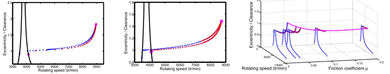
3000 4000 5000 6000 7000 8000 9000 1
1.5 2 2.5
Rotating speed (tr/min)
Excentricity / Clearance
(a) Forced response curve of finite ele-ment rotor for µ = 0
3000 4000 5000 6000 7000 8000 9000 0.8 1 1.2 1.4 1.6 1.8
Rotating speed (tr/min)
Excentricity / Clearance
(b) Forced response curve of finite ele-ment rotor for µ = 0.03
0 5000 10000 0 0.05 0.1 0.15 0.2 0 0.5 1 1.5 2 Friction coefficient µ
Rotating speed (tr/min)
Excentricity / Clearance
(c) Singular point tracking of Jeffcott rotor as a func-tion of fricfunc-tion coefficient µ
Figure 3:Assessments of finite element rotor (blue: stable solution; red: unstable solution)
The calculations for finite element rotor are carried out in Cast3mCAST3M (2014). Figure.3(a) represents the response curve with stable and unstable branches for the friction coefficient µ= 0. The black line stands for linear response. Two turning points are also detected. The response curve for µ = 0.03 is shown in Fig.3(b). Same as in Fig.??, the system has passed stable and unstable phases due to complex motion changes due to the strong non-linearity arising from contact. Similarly, not all bifurcations have been detected.
In Fig.3(c) the magenta line is directly calculated with the continuation technique and covers all the bifurcation points with respect to µ (from 0 to 0.2). This example illustrates that the continuation technique is able to locate directly the bifurcation points in applications of finite element analysis.
References
CAST3M. http://www-cast3m.cea.fr/. CEA (French Atomic Energy Commission), 2014.
G. V. Groll and D. Ewins. The harmonic balance method with arc-length continuation in rotor/stator contact problems. Journal of Sound and Vibration, 241(2):223 – 233, 2001. ISSN 0022-460X.
M. Lalanne and G. Ferraris. Rotordynamics prediction in engineering. Number vol. 2 in Rotordynamics prediction in engineering. John Wiley, 1998. ISBN 9780471972884.
EUROMECH-Colloquium 573 Coupling and non-linearities in rotating machinery. Aug 25-27 2015, Lyon, France.