HAL Id: hal-01738122
https://hal-ifp.archives-ouvertes.fr/hal-01738122
Submitted on 20 Mar 2018HAL is a multi-disciplinary open access archive for the deposit and dissemination of sci-entific research documents, whether they are pub-lished or not. The documents may come from teaching and research institutions in France or abroad, or from public or private research centers.
L’archive ouverte pluridisciplinaire HAL, est destinée au dépôt et à la diffusion de documents scientifiques de niveau recherche, publiés ou non, émanant des établissements d’enseignement et de recherche français ou étrangers, des laboratoires publics ou privés.
Development and Qualification of a Smeared Fracture
Modelling Approach for Transfers in Fractured Media
André Fourno, Christophe Grenier, Frédérick Delay, Hakim Benabderrahmane
To cite this version:
André Fourno, Christophe Grenier, Frédérick Delay, Hakim Benabderrahmane. Development and Qualification of a Smeared Fracture Modelling Approach for Transfers in Fractured Media. Ground-water in Fractured Rocks (IAH Selected Paper Series, volume 9), 2007. �hal-01738122�
Development and Qualification of a Smeared Fracture Modelling Approach for
Transfers in Fractured Media
André FOURNO1,2,*), Christophe GRENIER1), Frederick DELAY 2), Hakim BENABDERRAHMANE3)
1) CEA (Commissariat à l'Energie Atomique). C.E. Saclay. DM2S/SFME/MTMS - 91191 Gif sur Yvette Cedex. France 2) Université de Poitiers. Laboratoire Hydrasa. UMR 6532 du CNRS. Poitiers. France
3) ANDRA (Agence nationale pour la gestion des déchets radioactifs). DS/SMG. Parc de la Croix Blanche. 1-7 rue Jean Monnet. 92298 Châtenay-Malabry. France
*) now at IFP (Institut Français du Pétrole). Direction Ingénierie de réservoir. R320R. 1&4 avenue de Bois-Préau. 92852 Rueil-Malmaison Cedex. France
Modelling transfers in fractured media remains a challenging task for nuclear waste storage. In this context, flow velocities around a repository are assumed very small which makes matrix diffusion to play a major role in strongly retarding mass transfers. The development and qualification of a novel smeared fracture approach adapted to these conditions is presented. Flow and transport are solved using a Mixed Hybrid Finite Element method, limited here to 2D problems for the sake of simplicity. The geometry of major fractures and matrix blocks is accounted for without handling a huge dedicated meshing. The precision of the method is studied for various test cases, mesh sizes and transport regimes. It is shown that the smeared fracture approach is accurate while limiting computational costs for transfers at low velocity typical of post closure conditions.
Introduction
Within the field of nuclear spent-fuel storage, special emphasis is put on experimentation and simulation to improve the modelling capabilities in capturing the transfer of radionuclides within natural fractured media (GEOTRAP 2002; Chapman and McCombie 2003). Several issues make this modelling work a challenging task. Issues include the geometrical variability of the system, the scarcity of available data, and the strong contrasts in parameter values between mobile and immobile zones (Bear et al. 1993). Thus, experimental programs at underground laboratories provide site-specific data bases for testing and modelling programs. These programs are intended to provide a better representation and understanding of major processes. A detailed presentation of the present concerns in terms of research and development for the Äspö Hard Rock Laboratoratory of SKB (SKB, 2004).
This study was initiated within the SKB Task Force to focus on different issues linked to the Äspö site (South West Sweden) using the associated database. This site is one of the best characterized and best documented in the world and provides unique opportunities for realistic modelling exercises. Several international exercises were organized over the last decade within the Task Force to assess the different issues associated with nuclear waste storage. These exercises took advantage of the rich Äspö database and addressed topics related to flow and transport modelling at both local and regional scales (Äspö Web Site; Grenier and Benet, 2002; and Grenier et al. 2004).
The main objective of the study is to bridge between site characterization (SC) models and performance assessment (PA) models. SC models tend to be complex, incorporating detailed physical and geochemical properties, as well as calibrated on or constrained by short-term and small-scale in situ experiments. PA models, in contrast, can be simpler, limited to the main physical features, and are generally used to address uncertainties by simulating a range of possible configurations and parameter values. They apply to longer time ranges and larger spatial scales.
Because of the low conductivity of matrix blocks in crystalline, in this case granitic, media, flow primarily occurs along fractures, which are, for radionuclides, the main transfer paths. Transfer in these (more or less) complex conductive units is advective and dispersive. Nevertheless, interactions with the rock matrix and/or stagnant zones limit the velocity or the importance of mass fluxes. One of the key retention processes to be considered for transfer into low-permeability formations is diffusion into immobile zones. Fractions of the plume are temporally diverted from primary flow paths by diffusion into rock blocks (porous portions of the rock with negligible flow, fracture infilling materials, depositions onto fracture walls, dead end pores, etc.). This process is typically referred to as the matrix diffusion effect (Neretnieks 1980; GEOTRAP 2002). The importance of this phenomenon increases as the diffusion coefficient values increase, or with increasing contact time between the plume and the host rock. For a post-closure situation (natural flow and repository installed within low conductivity zones), the water velocity is very slow. As a consequence, matrix diffusion is likely to become an important mechanism in radionuclide transport.
Transfers in fractured media have already been subject to intense modelling work (e.g., Bear et al. 1993, Berkowitz 1994). Nevertheless, models incorporating detailed fracture geometry were mainly developed for flow situations encountered in rapid transfers more typical of experimental test cases. In particular, discrete fracture network approaches represent flow and transport in a fractured network by means of a discrete network of simple interconnected features. Such models are computationally efficient and can account for various transport phenomena. Matrix diffusion is implemented similarly to a retardation factor along each connecting feature and corresponds to a limited or unlimited orthogonal 1D diffusion. Nevertheless, these models are not adequate for slow transfers in a fractured block since matrix diffusion is no longer limited to
the close vicinity of the fractures but is able to connect wide portions of the fractured block. The actual block geometry should then be taken into account.
Our smeared fracture approach involves a continuum approach to the geometry of the fractured rock allowing for actual geometry of the matrix zones to be represented. The basic philosophy is to provide a versatile tool for system calibration (based on in situ pumping and tracer tests). The main features of the fractured block are represented (main conductors at the scale of the studied block) whereas minor fracturing is homogenized. Identification is then reduced to a limited number of properties associated with some major features. Nevertheless, the geometry of these features can be easily modified for calibration since no dedicated meshing of the geometry is considered. The method handles a regular meshing over which specific hydrodynamic properties make the difference between fractures and matrix blocks.
The basic idea of the approach is not to mesh the fracture network but to consider the presence of fractures by means of continuous heterogeneous fields (permeability, porosity, head, velocity, concentration, etc.). This approach, previously followed by others (e.g., Svensson 2001 and Tanaka et al. 1996), is referred to as the smeared fracture approach and has an important advantage since no dedicated spatial discretization effort is required (a regular mesh is used and simulations can be done on a rough grid, which saves computer time). This makes this approach very promising when accounting for heterogeneity and prediction uncertainty within a Monte Carlo framework. Furthermore, the geometry of the matrix blocks where transfers proceed by diffusion is fully taken into account contrary to classical simplified 1D approaches. Nevertheless, the continuous heterogeneous field representation of a fractured medium requires a homogenisation process at the scale of the handled mesh and constant mesh size might not be appropriate to simulate contrasted transitory transport regimes. In the following, the principle of the method is presented as well as its development and qualification. The approach was implemented and tested in our simulation code, Cast3M (Cast3m Web Site). Development of the smeared fracture approach for the MHFE scheme
♦Geometrical features
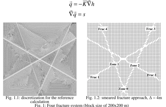
The first step consists in selecting within the regular -grid the meshes containing a fracture. In doing so, care is taken to assure connectivity across the elements to form flow tubes. In a 2D space, fractures are considered as piecewise linear objects (segments). An example is provided in Fig. 1.1 and Fig. 1.2 for the 4 conductor case considered below: the meshes of the regular grid intersected by a fracture are identified (voids on the figure) and assembled to form a connected tube-like geometry.
♦Steady-state flow problem
The equations governing steady-state flow are classically, for q (ms-1) Darcy velocity, K (ms-1) permeability, h (m) head, s (m3s-1) source term.
s
q
h
K
q
=
∇
∇
−
=
r
r
r
r
(1)Fig. 1.1: discretization for the reference
calculation Fig. 1.2: smeared fracture approach, ∆ = 4m Fig. 1: Four fracture system (block size of 200x200 m)
Eq. 1 is solved with the smeared fracture approach but in using equivalent permeability values. These values are associated with the elements selected and computed to provide net water flux conservation. The homogenization procedure is applied at the fracture level and directly allows for exact flux at the outlets. This differs from other smeared fracture approaches (Tanaka et al. 1996; Svensson 2001) treating the
homogenization process as averaging at the level of each mesh and using the well known Finite Volume scheme to differential equations. Our approach allows for exact restitution of the total water flux transiting through each fracture considered individually. Another advantage is that the lateral extension of a fracture is roughly limited to the size of one mesh (Fig. 1.2) whereas other smeared fracture approaches implemented with equivalent properties based on volume averages and a finite-element scheme for flow resolution lead to larger lateral smearing of the conducting features (Svensson 2001). The remaining point is to choose a parameter value for fracture intersections: the maximum of the considered properties is applied. This is a deviation from the strict equivalence obtained for single conductors and the accuracy of a simulation at the scale of an entire network is to be tested as regard reference calculations.
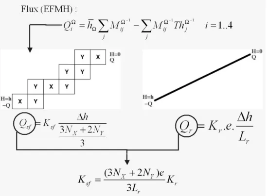
Homogeneity of fracture properties are assumed here but variations of properties along any of the conductors could easily be taken into account. The actual homogenization procedure used for the flow problem (determination of equivalent transmissivity) is shown in Figure 2.
Fig. 2: Basic concept of the smeared fracture approach
A mixed and hybrid finite-element (MHFE) scheme (Mosé et al. 1994) is used as flow solver. This numerical scheme provides accurate mass conservation even for highly heterogeneous media. This conservation is guaranteed for each mesh by the introduction of four unknowns also called traces and affected to the centre of the mesh edges in addition to the classical unknowns corresponding to the centre of the meshes. These traces allow for joint estimation of fluxes (gradients) as well as values of unknowns within the mesh. Steady-state flow is only calculated in the fractures, the matrix blocks being considered as impervious. For a single conductor (Fig. 2), heads at upstream and downstream tips of a fracture are related through a 1D tube involving two types of elements:
• X-type cells for which flow entering one side exits through the opposite side.
• Y-type cells for which flow enters and exits through adjacent sides. These two types of cells and their boundary conditions are illustrated on Fig. 3.
Fig. 3: X- and Y-type cells
Considering both the boundary conditions and the discretized Darcy flux for MHFE scheme, it is possible to find outlet flux for each cell type (Table 1).
X-type cell Y-type cell h K Q Q sf X X =− =− ∆ 3 1 Q Q K h sf Y Y = =− ∆ 2 3 2 1
Table 1: numerical flow for X and Y elements
The flow tube being only composed of the two types of cells and considering the mass balance between two cells, it is possible to calculate the tube numerical flow. The equivalence between the total flux through the reference fracture and the equivalent conductor is written based on equality between the real flux in the fracture and the numerical one in the tube (Fig. 2).
For the discretization scheme used, the relation between flow and head difference at the inlet and outlet can be easily computed. For a given angle, the number of cells included as a series in each flowing tube (NXof the X-type and NY of the Y-type) can be counted and leads to the equivalent permeability:
r Y X sf K L e N N K 3 ) 2 3 ( + = (2)
where e, L and K are the thickness, the length and the permeability of the fracture, respectively. The subscripts sf and r are related to smeared fracture equivalent property and reference property, respectively. For the sake of illustration, considering a horizontal fracture leads to NY =0and knowing thatNX∆X =Lr, the former expression simplifies to:Ksf∆X =Kre. This equation expresses equality in transmissivities providing identical total water fluxes. This equivalence is exact for a single conductor. Nevertheless, dealing with several fractures introduces deviations from this due to the treatment of intersections. For an intersection of several fractures, maximal transmissivity is considered. The method is assessed below by comparison with reference calculations.
♦ Transport problem
Two distinct transport modelling strategies were implemented for simulating transport in a fractured rock with a smeared fracture approach: a Lagrangian method and an Eulerian one.
The Lagrangian method is not well suited to the actual flow field for the smeared fracture approach. Indeed, for Y-type meshes, the variability of Darcy velocity over the whole grid is very large, leading to extremely high and low transit times depending on the location of the particle entering the mesh. This difficulty was circumvented by constraining transport paths to controlled flow lines. This is achieved for a release position at the centre of the element edge leading for X and Y type elements to exit positions similarly located at the centre of the edges. Associated travel times are easily computed and yield values of the equivalent porosity consistent with volume ratios. This method was implemented in Cast3M for pure advection allowing for the computation of streamlines. It is computer efficient and was tested with success as regard reference simulations. It requires a theoretical derivation of equivalent porosity (based on summation of transit times associated with NX X-type meshes and NY Y-type meshes along a single fracture) as well as slight modifications of the particle tracking procedure available in the Cast3M code. However, this approach cannot be extended to other processes such as a diffusion because particles would move to other flow lines than the one selected. Thus, the Lagrangian approach is limited to purely advective transport in the fracture network. The Eulerian approach has more potential in this situtation and better fits into the expected transport regimes for long-term transfers in a low permeability zone hosting a waste storage. These regimes include purely diffusive process for the matrix blocks, advective and dispersive processes inside fracture network and sorption for both. For the MHFE scheme implemented, advection is introduced as a source term in the classical Eulerian equation (Dabbene et al. 1998). As a consequence, one does not face the same problems as for the Lagrangian approach. Inclusion of diffusion in matrix zones is straightforward, matrix blocks are meshed and corresponding properties are assigned. One of the most interesting advantages of this approach is that matrix blocks geometry are actually represented. This approach is appropriate for low Peclet Numbers or when transport regimes in the fracture network (advection dominated) and in the matrix blocks (purely diffusive in our approach) are not too much contrasted in terms of characteristic residence times. These conditions are met for slow motion of the water in the system. This is the case for post-closure transfer regimes. The Eulerian approach to transport in a fractured block is developed below.
The mass transfer including advection and dispersion (or diffusion) as well as linear sorption obeys the general following equation:
)
.(
D
C
C
q
t
C
R
r
r
r
−
∇
∇
=
∂
∂
ω
ω
(3)where C stands for concentration (kg/m3), R for retardation coefficient,
ω α q
d
D= f + is the dispersion tensor, ωthe porosity, d the pore diffusion coefficient (m2/s), αthe dispersivity (m), and q the Darcy velocity (m/s). Transfers within the fracture network and matrix blocks are considered.
The smeared fracture approach for transport relies on the steady state flow modelling and its equivalent parameter estimation presented above. The transport phase requires the estimation of other equivalent properties associated with the fracture elements (i.e., dispersion tensor and porosity assumed as a scalar). The final transition time through the system adds all the transfer times for all elements met on the path. Thus, the exact equivalent porosity is provided byωsf :
r sf fr r fr sf
V
V
ω
ω
=
(4)where ωr stands for real fracture porosity, Vfr for fracture volumes associated with smeared fracture meshes (sf subscript) or actual fracture (r subscript).
The equivalent dispersion tensor is here derived as a scalar value based on the same considerations as those for the derivation of equivalent transmissivity.
N
X is the number of the X-type meshes andN
Y the number of Y-type ones. The dispersive part of the transport equation (dispersive mass flux) is analogous to the flow equation (water flux) yielding the following diffusion dispersion coefficient for a single conductor:r r Y X sf D L e N N D 3 ) 2 3 ( + = (5)
When dealing with fracture networks, the same procedure as for flow is applied to fracture intersections, the dispersion coefficient assigned is the maximum value calculated in the intersection mesh.
Qualification strategy
The smeared fracture procedure allows for a priori exact computation of water and mass fluxes in single fractures, but the approach has to be qualified for reference calculations. The most obvious source of difference is expected for coarse meshing when modelling a finely fractured rock: digitization of the geometry is not sufficient to represent the actual complexity. A criterion assessing the lower limits in mesh size to satisfyingly account for such geometrical aspects is introduced below. Qualification is required because of numerical constraints which are twofold. First, to achieve numerical stability and precision of the results, mesh Peclet numbers should be lower than unity. This means that the mesh size should be lower than dispersivity or equivalently that the coarser the mesh, the more dispersive the transport for the smeared fracture approach. Second, transport is considered in highly contrasted media, including slow diffusive transfers in the matrix blocks and comparatively rapid transfers in the fractures. In the smeared fracture approach, this system is represented with a single mesh size whatever the medium, fracture or matrix. This possibly leads to lack of precision in the simulations or even instabilities and requires a few tests to assess the limits of the approach. Criteria quantifying the level of numerical precision are introduced below.
The smeared fracture approach was tested through a series of configurations including different fracture network geometries as well as a variety of parameter values and flow velocities. The geometries tested for 2D cases are given in Fig. 4. They include a single fracture configuration (for checking the code implementation), a four fractures academic case, a more realistic 2D fracture network inspired from the situation at the Äspö underground laboratory (200 m Block Scale Experiment).
The basic idea for the qualification study is to make to vary time and space discretization for smeared fracture simulations and compare the results with reference simulations. References are obtained from either analytical solutions or computed solutions over a huge dedicated meshing.
Fig. 4: set of studied geometry with increasing levels of complexity and realism. Flow (limited to fracture network)
Steady-state flow simulations were carried out for various geometry and flow parameters. Main results are: 1) the smeared fracture approach yields accurate fluxes for single fractures as well as good precision on fracture networks provided a sufficiently refined meshing is used; 2) total fluxes exiting the system are very robust (low sensitivity to the mesh size). The same conclusion holds for fluxes within main conductors that vary within some percents even for coarse meshing; and 3) fluxes in minor conductors can locally vary more strongly (ten to twenty percent). As a consequence, the main constraint on discretizing size is geometrical and rather intuitive: the mesh size should be small enough to account for the actual connectivity of the conductors. More difficulties occur in modelling transport. Although flow is considered as constant over time, transport is transient, which leads to specific numerical constraints.
Transport in a single fracture system
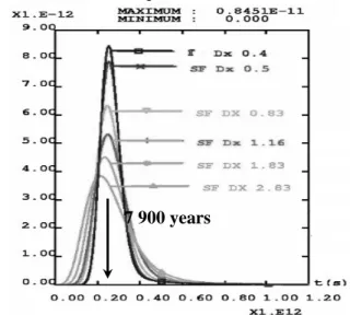
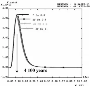
For the single fracture system of Fig. 4, the transport of a point source concentration injected in the middle of the fracture is simulated. Breakthrough curves for transported mass flux exiting the block are represented in Fig. 5. The mesh size is made to vary between 0.5 and 3 m and the "reference" calculation in Fig. 5 it that for a mesh size of 0.4 m. With a rough meshing, the concentration peak levels decrease and breakthrough curves show a larger spreading in time. Nevertheless, peak arrival times show limited sensitivity to mesh size. Note that this first validation scenario only considers transport (advection and dispersion processes) in the fracture and the curve spreadings are due to numerical dispersion.
Fig. 5 : Total fluxes at the outlet (no matrix diffusion, single fracture case)
For transient problems such as transport, two numerical criteria must be considered: 1) the Courant or CFL Number, applying to advective transfer and 2) the Fourier Number, associated with diffusive transfer. Ratio of both is the Peclet Number. Implicit scheme is considered for diffusive transport. This allows for resolution with large time steps but introduces a minimal time step value to preserve the monotony of the solution and achieve good precision for the results. The limit is provided in the following expression involving the Fourier Number:
1 < ∆ ∆ = ω t q NC (CFL criterion) and 2 1 2 > ∆ ∆ = ω αq t
Fo (Fourier criterion for
ω α ω α q q d D= f + ≈ ), where ∆t is the time step and ∆ the regular mesh size. Ratio between both expressions corresponds to grid Peclet:
2 < ∆
α (6)
This expression implies that grid size should be lower than dispersion coefficient. In other words, transport cannot be simulated accurately with a dispersivity value lower than the mesh size.
Transport in a single fracture including diffusion in matrix blocks
This geometry (see Fig. 4) was tested for three flow regimes leading to breakthrough curves provided in Fig. 6.1: (i) a dominantly advective regime K1 (negligible matrix diffusion), (ii) an intermediate regime K2, (iii) a dominantly diffusive regime K3 (large matrix diffusion). In Fig. 6.1, the breakthrough curves are scaled onto the peak level of the slowest transport conditions. Matrix diffusion leads to strong delays in peak arrival times. Modifications of the shapes of the breakthrough curves are also observed, with a strong tailing effectdue to the slow mass release from matrix zones.
In Fig. 6.2 to 6.4, the sensitivity of the breakthrough curves at the limits of the domain is presented for the smeared fracture approach (different spatial discretizations) and for the reference simulation (achieved by means of a solution computed over a refined meshing, see black curves with squares).
Fig. 6.1: Output mass flux for the three flow regimes Fig. 6.2: Total fluxes at the outlet for regime K1
Fig. 6.3: Total fluxes at the outlet for regime K2 Fig. 6.4: Total fluxes at the outlet for regime K3 With a weak matrix diffusion (Fig. 6.2 for K1), results are similar to those without matrix diffusion (see above). For higher matrix diffusion (cases K2 and K3 of Fig. 6.3 and 6.4), classical tailing effects appear. For identical grid size variations (50 cm to nearly 3 m), discrepancies in peak level, arrival times and spreading of
7 900 years
grid size is not necessary to match a given precision level of the results. These observations are explained by considering an additional criterion, which is the Fourier Number associated with diffusion in matrix zones. In line with former explanations, matrix Fourier Number should be large enough:
6 1 2 > ∆ ∆ =d t
Fo m , that is, for a given time increment, spatial discretization should be sufficiently small. Nevertheless, breakthrough curves in Fig. 6.1 show that matrix diffusion introduces delayed peak arrival times. When velocity in the fracture decreases, the mean transit time also decreases and is more controlled by matrix diffusion. Time steps calculated from a CFL number should include this retardation effect (time steps should be chosen larger). This delay can be estimated as a retardation coefficient based on the analytical solution to transport by advection in a single fracture and 1D orthogonal diffusion in an infinite matrix. This solution writes for a continuous injection at the inlet of the fracture (Neretnieks 1980; Bear et al. 1993):
) ( ) ( ) , ( 0 0 fr w w m m w fr w m m w t t t e t d erfc t t e t d erfc C t t C − − − − = ω ω ω ω (7) with tw the travel time by pure advection in the fracture. The output peak arrival time ts can be obtained from
the derivation of Equation (7) and the associated retardation coefficient RP writes:
w w p s fr m m p t t R t e d R = + = 2 2 ) ( 3 2 1 ω ω (8) For a velocity, fr q
ω , and a contact incremental time
5 100
p s R t t
∆ = (i.e. in considering that the maximum simulation time is five times the estimated peak arrival time and that 100 time steps are computed for this time lag), the associated penetration length in the matrix can be obtained from the following equation:
100 10 2 2 2 w p m m t R d t d = ∆ = η
Thus, the Fourier Number previously constrained to values larger than
6 1
yields a constraint on ∆ (∆ < 3
η
), expressed in terms of η, or, expressed in terms of matrix properties:w p mR t d 10 3 < ∆ (9)
This criterion adds to the former ones when matrix diffusion is included. Note that this criterion for matrix diffusion imposes a small discretization to perform accurate calculations which make the latter more time-consuming. This criterion is easier to satisfy when matrix diffusion coefficient, retardation coefficient associated with the tracer and additionally water arrival times are large. Large arrival times are achieved for long travel distances and/or low fluid velocities. This is precisely the situation considered for post closure natural flow in low-permeability fractured media.
Finally, this approach is very interesting for long time scale and post-closure simulations. A smeared fracture approach with coarse grids remains efficient with low computation costs when the diffusive regime is dominant among transport mechanisms. For other regimes and accurate results, a finer discretization is required.
Transport in the four fractures system without matrix diffusion
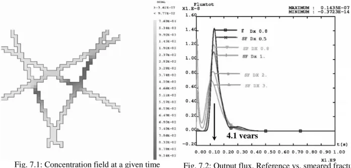
The smeared fracture approach for Eulerian transport within a fracture network was tested on the 4 fractures geometry (Figs. 1 and 4). The results were compared to simulations performed over the dedicated meshing depicted in Fig. 1.1. The flow direction is from bottom left to upper right corners of the domain. The initial transport conditions are a point instantaneous injection of a unit concentration in one mesh of the domain. Several release positions were studied corresponding to the different zones mentioned on Fig. 1.2. Focus is put here on the Zone 0 case, located upstream at the intersection of two main fractures (numbered 3 and 4). Globally, the plume first migrates within both conductors at different velocities, then separates at intersections and reaches finally the outlets at the upper right corner of the domain. Different paths are therefore experienced which leads to the dispersion of the plume over the network. The quantities measured are
breakthrough curves at the limits of the domain, concentration fields at different times, temporal evolution of the masses in the fractures and at fracture intersections. A concentration field before peak arrival time is given in Fig. 7.1 for the smeared fracture simulation.
Fig. 7.1: Concentration field at a given time Fig. 7.2: Output flux. Reference vs. smeared fracture In this study, different levels of discretization have been considered and the limitations of the smeared fracture approach are revealed in two ways :
◆ Two curves (Fig. 7.2) show abnormal evolutions with a very early exit time followed by a classical bell-shaped time distribution. These curves correspond to coarser discretizations for which the geometry of the fracture network is badly represented, which , in turn, yields an artificial excess of connection between the network and the edges of the domain.
◆ The other breakthrough curves from finer discretization (an example with meshes of 1 m on a side is given in Fig. 7.1) provide expected results including limited numerical dispersion compared with the reference calculation. Fig. 7.2 a second peak of weak intensity but the smeared fracture approach tends to smooth this kind of detailed feature. This small peak is related with mass arrival from a minor travel path that is not distinctively represented by the smeared fracture approach.
When studying in details the eventual discrepancies in the fracture network, for instance within single conductors, results show (not illustrated here) that the mass sharing and the residence time distribution in minor conductors is less precise than in the major fractures. This is mainly related to larger relative errors on the flow field inside branches of the network with small water fluxes. Nevertheless, whatever the approach (reference or smeared) it is necessary to choose the time step carefully. Since main transport features are related to major conductors, CFL are calculated according to velocities in these units. Precision for advective transport in minor units is necessarily reduced.
In summary, results show that the grid size should be chosen small enough to account for a good digitization of the network geometry. The other effects related with coarse discretization are overall smoothing of breakthrough curves. Nevertheless, if we pay attention to these limits, the approach is promising. Whatever the initial position of the plume, peak arrival time is met with errors close to 5% whereas peak maximum more largely differs (0% to 22% depending on the discretization level and therefore on the numerical dispersion by the MHFE). In terms of computational costs, a transport scenario over a smeared fracture discretization preserving accuracy is calculated more rapidly, about a factor two, than the reference simulation.
Transport in the four fracture system including matrix diffusion
Several test cases were considered for different flow velocities. Fig. 8 shows the breakthrough curve collecting all outlets at the domain boundaries. The solid line with squares corresponds to the reference calculation. Matrix diffusion leads to very a smooth breakthrough curve for the total flux exiting the domain and there is almost no difference between curves computed with various mesh sizes.
Fig. 8: total flux at the outlets for the more diffusive regime (K3)
The conclusions drawn from the single fracture case can be extended to this more complex 4 fractures network. For different transport regimes, precision in peak level and arrival time is within 20% of reference case for lower CPU time (refer to Table 2 for more quantitative results). Precision of the results increase here with the importance of matrix diffusion.
Dx=0.6m Dx=0.8m Dx=1m
K1 0% 16% 23%
K2 0% 15% 21%
K3 3% 4% 5%
CPU time reduction 70% 40% 30%
Table 2: Peak level relative error and CPU time reduction 2D system from a block at Äspö
A more realistic system is considered here (for both geometry and parameter values) to demonstrate the applicability of the approach to real cases. The 2D Äspö case considered here is that of a section across the actual 3D geometry of a 200 m fractured block at the Äspö underground laboratory (see Fig. 9.1). The initial conditions (I.C.) correspond to a pulse unit mass injected at a fracture intersection (see Fig. 9.2). A head gradient of 3
10− is taken, in agreement with local natural flow conditions (from upper right to bottom left corners in Fig. 9.2).
Fig. 9.1: Äspö fractured block (200x200x200 m) and section plane of 2D network of Fig 9.2
Fig. 9.2: 2D fracture network (a section across the 3D block )
In a first step, the system was modelled without matrix diffusion. The breakthrough curve collecting all outlets at the domain boundaries show several arrival peaks. They correspond to different paths followed by the plume. The smeared fracture approach yields results matching fairly well reference calculation again performed over a dedicated meshing (see Fig. 10.1 and 10.2 for the outlet of fracture #8).
Fig. 10.1: Total mass flux exiting the block Fig. 10.2: Outlet mass flux, fracture 8
In a second step, matrix diffusion is added and the results shown in Fig. 10.3 for the smeared fracture approach. Reference calculations were not performed in this case. Qualitative evolution of mass flux confirms intuition; the role played by the matrix diffusion is classical, yielding: 1) an arrival time delay, 2) a smoothing effect, 3) a decrease of peak value and 4) a tail. Moreover, peak arrival time is close to the analytical estimate from Equation (8).
Fig. 10.3: Total mass flow (with matrix diffusion)
Results show that the smeared fracture approach can cope with a realistic test case. It provides overall good results with lower computer costs:
• The peak arrival times are in agreement with the reference case or estimates from analytical expressions.
• The precision in peak value depends on discretization (numerical dispersivity) and can be controlled on the basis of numerical criteria in Equations. 6 and 9 and on previously discussed geometrical considerations.
• When the diffusion effect smoothes the breakthrough curves, accuracy of smeared fracture calculations improves.
Conclusions and perspectives
This smeared fracture modelling approach provides relevant results in terms of precision, computational costs, and numerical stability. The quality of the results depends closely on transport regimes in the fractures and on spatial discretization. The domain in which the smeared fracture approach is the most efficient is that of long-term transport (low velocities) when explicit 3D modelling of matrix block geometry is required due to large penetration depths of the concentration into the rock. Nevertheless, a first criterion for the quality of the
79 years
more precisely connectivity. Second, equations 6 and 9 provide the higher bounds of the mesh size that guarantees the capture of transport phenomena within fracture network and matrix zones with sufficient precision of the simulations. The next needed step in the development of the smeared fracture model is to address 3D geometry. Meshing and definition of equivalent properties are already available. The code has been tested and qualified for simple cases. An application to the Äspö site (Sweden) is in progress. Another future prospect is relative to the implementation of matrix diffusion for higher velocity cases or shorter time scales. This will be achieved within our Eulerian scheme by means of semi analytical expressions for source terms corresponding to 1D orthogonal diffusion processes.
References
Äspö Web Site. Web site for the Äspö Task Force under www.skb.se/templates/SKBPage____2636.aspx Bear J, Tsang C.F, De Marsily G (ed.) (1993) Flow and contaminant transport in fractured rock. Academic
Press.
Berkowitz B (1994) Modeling flow and contaminant transport in fractured media. Advances in Porous Media. Volume 2. Corapcioglu Ed. Elsevier.
Cast3m Web Site. Web site for computer code Cast3m, under www-cast3m.cea.fr/cast3m/xmlpage.do?name=presentation
Chapman N, McCombie C, (2003) Principles and standards for the disposal of long lived radioactive wastes. Waste Management Series. Elsevier.
Dabbene F, Paillere H, Magnaud J.P (1998) Mixed Hybrid Finite Elements for transport of pollutants by undergound water. Proc.10th conference on finite elements in fluids, Tucson, Arizona.
GEOTRAP (2002) Radionuclide retention in geologic media. Workshop proceedings. Oskarshamn, Sweden, May 2001. OECD/NEA.
Grenier C, Benet L.-V (2002) Groundwater flow and solute transport modelling with support of chemistry data, Task 5, Äspö Task force on groundwater flow and transport of solutes, SKB International Cooperation Report, IPR-02-39
Grenier C, Fourno A, Mouche E, Delay F, Benabderrahmane H (2004) Assessment of Retention Processes for Transport in a Fractured System at Äspö (Sweden) Granitic Site: From Short-Time Experiments to Long-Time Predictive Models. Proceedings of Second Inernational Symposium on Dynamics of Fluids in Fractured rocks, Berkeley (California, USA), LBNL Report 54275 pp. 242-247.
Mosé R, Siegel P, Ackerer P, and Chavent G (1994) Application of the mixed hybrid finite element
approximation in a groundwater flow model: Luxury or necessity?, Water Resources Research, 30(11), pp. 3001-3012.
Neretnieks, I (1980) Diffusion in the rock matrix: an important factor in radionuclide retardation ? Journal of Geophysical Research, Vol. 85, No B8.
SKB (2004) RD&D programme 2004 - Programme for research, development and demonstration of methods for the management and disposal of nuclear waste, including social science research. TR-04-21, SKB report.
Svensson U (2001) A continuum representation of fracture networks. Part I: Method and basic test cases. Journal of Hydrology 250, pp. 170-186.
Tanaka Y, Minyakawa K, Igarashi T, Shigeno Y (1996) Application of 3D smeared fracture model to the hydraulic impact of the Aspo tunnel. SKB Report. ICR 96-07.