HAL Id: ineris-00973286
https://hal-ineris.archives-ouvertes.fr/ineris-00973286
Submitted on 4 Apr 2014HAL is a multi-disciplinary open access
archive for the deposit and dissemination of sci-entific research documents, whether they are pub-lished or not. The documents may come from teaching and research institutions in France or abroad, or from public or private research centers.
L’archive ouverte pluridisciplinaire HAL, est destinée au dépôt et à la diffusion de documents scientifiques de niveau recherche, publiés ou non, émanant des établissements d’enseignement et de recherche français ou étrangers, des laboratoires publics ou privés.
A large scale continuum-discrete numerical modelling :
application to overburden damage of a salt cavern
Mountaka Souley, Diego Mercerat, Lynda Driad-Lebeau, Pascal Bernard
To cite this version:
Mountaka Souley, Diego Mercerat, Lynda Driad-Lebeau, Pascal Bernard. A large scale continuum-discrete numerical modelling : application to overburden damage of a salt cavern. Symposium Post-Mining 2008, Feb 2008, Nancy, France. pp.NC. �ineris-00973286�
A LARGE SCALE CONTINUUM-DISCRETE NUMERICAL MODELLING: APPLICATION TO OVERBURDEN DAMAGE OF A SALT CAVERN
SOULEY Mountaka1, MERCERAT Diego2, DRIAD-LEBEAU Lynda1, BERNARD Pascal2
1
INERIS, Ecole des Mines, Parc de Saurupt; CS14234, 54042 Nancy Cedex – France; [email protected]; [email protected]
2
Equipe de Sismologie – IPGP, 4 Place Jussieu – 75005 Paris cedex - France ; [email protected]; [email protected]
ABSTRACT: With the objective to better understand the evolution of overburden damage on top of an
underground solution mining, an in-situ experiment is undertaken above a salt cavity in the Lorraine region (NE of France). The overburden overlying the salt cavity is characterized by a competent layer where most brittle damage, with the associated microseismicity, is expected. This work presents a coupled continuum-discrete modelling approach to simulate the mechanics of fracture initiation and propagation in the rock mass, a continuum approach for the marls and salt layers, and a discrete micromechanical approach for the competent layer. A methodology of a large scale coupled continuum-discrete modelling is proposed and applied to the site of Cerville-Buissoncourt. The numerical verification of the hybrid approach response is achieved by comparing the results with those from the fully continuum model at the site scale when the competent layers behave elastically. The first results of a large scale modelling based on the hybrid approach suggest that the fracture mechanisms in the competent layers are predominantly tensile. Finally, these explicit microcracking simulations open interesting perspectives for comparison with the observed microseismicity of the study area (transient pressure experiment or future final collapse).
KEYWORDS:cavern, numerical modelling, continuum-discrete, overburden, damage.
RÉSUMÉ: Dans l’objectif de mieux comprendre la microsismicité induite dans des mines de sel, une
expérimentation in situ a été réalisée sur une cavité saline de la région Lorraine (Nord-Est de France). Le recouvrement est caractérisé par la présence d’un banc raide dans lequel l’essentiel de l’activité microsismique est attendue lors de la reprise de l’exploitation. Ce papier présente une modélisation basée sur une approche couplée : continue (pour les marnes et le sel) et discrète (pour les bancs raides) pour évaluer les mécanismes de développement des fractures dans le recouvrement. Une méthodologie de modélisation à grande échelle couplant les approches continue et discrète a d’abord été proposée, puis appliquée au site de Cerville-Buissoncourt. La validation numérique de cette approche hybride est réalisée par comparaison avec la réponse d’un calcul continu à l’échelle du site. Les premiers résultats de cette modélisation hybride à grande échelle montrent que les mécanismes de fracturation prédominants dans les bancs raides restent les tractions. Ceci ouvre des perspectives intéressantes pour des confrontations avec les mesures qui seront enregistrées lors de l’effondrement provoqué (essai de pression, future effondrement après la reprise de l’exploitation).
1. Introduction
A large research project has been launched by GISOS1 in order to identify and evaluate the capacity of geophysical (microseismic, hydroacoustic) and geotechnical (extensometer, inclinometer) techniques for monitoring underground growing cavities due to salt dissolution (solution mining). A part of this research program focuses on two complementary axes: (1) the validation of induced seismicity monitoring techniques in salt mine environments, and (2) the numerical modelling of deformation and failure mechanisms with their associated acoustic emissions, as well as the induced microseismicity.
Previous studies on induced seismicity of underground growing cavities (Johnston and Einstein 1990, Mendecki 1997) confirm the presence of microseismic events associated with the progressive damage of the overburden until its final collapse. Continuous monitoring of such microseismicity may provide crucial information for stability analysis of the area surrounding the cavity. In order to validate such seismic monitoring techniques, a local microseismic network has been installed over a site test at Cerville-Buissoncourt (Lorraine, France), where a stable brine filled cavity is nowadays located (Mercerat et al, 2007). When the salt exploitation restarts, the spatial and temporal evolution of seismic event locations and magnitudes can be analysed and compared with the results of geomechanical modelling.
Numerical modelling of such complex process requires a large scale model which takes into account both the cavity evolution within the salt layer and the mechanical behaviour of the overburden layers where high deformation and fracturing are expected. To achieve this scientific challenge (experimental and numerical through geophysics and geomechanics fields), a coupled continuum and discrete modelling strategy is adopted.
This paper focuses on the feasibility to achieve the previous scientific objective and presents a methodology of numerical modelling the induced microseismicity location in the competent layers through the microcrack distribution. From numerical point of view and in order to take into account the elasto-brittle behaviour of the competent layers, where most of the seismic damage is expected, we use the code PFC (Particle Flow Code in 2D) based on the discrete element method. To describe the behaviour of the other layers (mainly composed of marls and salt) which present more ductile and/or viscoplastic behaviour, a continuum approach based on the FLAC code (Fast
Lagrangian Analysis of Continua) is used to account for different mechanical behaviours. It is
interesting to note that recent work published by Cai et al. (2007) followed a similar strategy to take into account explicit acoustic emission simulations near an underground excavation.
A large scale continuum model assuming an elastic perfectly plastic behaviour of the competent layers has been firstly performed in order to establish the suitable boundary conditions with regard to the actual cavity size. Secondly, a fully hybrid continuum-discrete model is developed. Comparison between the results of the two mentioned models allows us to validate the developed continuum-discrete model (microproperties used in the PFC inclusion modelling the competent layer, its lateral extension and velocity-force exchanges at the boundaries between continuum and discrete domains).
1
Research Group for the Impact and Safety of Underground Works involving French institutions INERIS, BRGM, INPL and Mining School of Paris.
2. Site description
2.1. Brine cavity, overburden characteristics and microseismic network
The brine cavity of Cerville-Buissoncourt (Lorraine, France) is actually located within a salt layer at about 180 m depth and presents an irregular shape that, in first approximation, can be considered a cylindrical cavity of 180 m of diameter and 50 m high. A scheme of the instrumented site with a schematic geological section of the area is shown in figure 1. Typically, the overburden is characterized by a series of intercalated anhydritic marls lying over the salt layer, and on top of them, the presence of a competent dolomite layer of 8.5 m thickness which presents elasto-brittle mechanical behaviour, and it is located approximately 60 m above the salt layer. This layer corresponds to what is known as the ‘Beaumont dolomite’, and it represents the level where most of the seismic damage is expected, when the salt exploitation restarts and the cavity will migrate towards the surface.
A microseismic network has been installed over the stable underground brine filled cavity of Cerville-Buissoncourt. The network includes four 3D components and three 1D component seismometers located at different depths (between 35 m and 125 m) in cemented boreholes distributed around the study area (figure 1). The frequency band of the geophones is between 40 Hz and 1 kHz. There is one station per borehole, except for the deepest one at the centre of the array right above the cavity (M6), where one 1D station at the surface and two 3D stations are located at 60 m and 125 m depth (Beaumont dolomite level). The lateral extension of the array is about 400 m by 600 m, and it presents reasonable azimuthal coverage (major gap of ~130° at the centre of the array).
More than 1000 microseismic events were recorded between January 2005 and September 2007. As an event, we denote in this work, a recorded file by the acquisition system used in trigger mode with recording time window of 0.8 seconds. In fact, more than 75 % of the events are grouped in clusters of time duration between 3 to 30 seconds (recorded by almost continuous triggering of the acquisition system). This activity is clearly not related to classical shear slip mechanisms induced by hard rock fracturing.
Figure 1. (Left) View of the instrumented salt cavity. (Right) Scheme of the E-W vertical section with main lithological units and location of microseismic 3D stations (red triangles) and 1D stations (blue triangles)
2.2. Transient pressure experiment
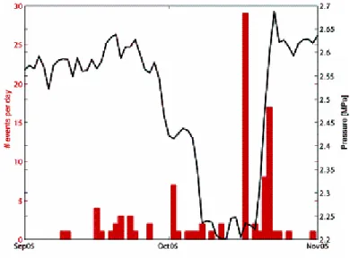
Currently, the cavity is full of saturated brine inducing a significant pressure on its walls (~2.5 MPa) to keep the overburden mechanically stable. In October 2005, a transient pressure experiment has been carried out in the cavity, in order to analyse the mechanical response of the overburden and to check the sensitivity of the whole instrumentation. The experiment consisted of a pressure drop of around 0.4 MPa (30 m of brine column height), followed by a stable phase of one week, and a latest phase of pressure raise up to the original level of 2.5 MPa (figure 3). During the pressure raise, two of the clustered groups of events were recorded by all the stations (16 and 18 seconds of duration, respectively). While the pressure drop did not produce any significant seismic activity, except for a small cluster of 3 seconds of duration. This observation suggests that the increase in pressure within some fractured layers on the top of the cavity could produce the observed induced seismicity.
Figure 2. Number of events per day recorded while the transient pressure experiment in the cavity. The activity is concentrated in the pressure raise (two clusters of 16 and 18 seconds of duration)
2.3. Laboratory characterization
A large number of laboratory tests have been carried out on SOLVAY S.A samples to characterize the geological formations of interest for this study. Some of them are available (by courtesy) for this study. In particular, the Beaumont dolomite and the anhydrite facies present a rather high Young modulus (E≈80 GPa) and uniaxial compressive strength (σc≈200 MPa) for typical sedimentary
rocks. The tensile strengths of both facies measured by Brazilian tests are also high. On the other hand, the mean values found for samples extracted from the intercalated marls located between the salt layer and the Beaumont dolomite are much lower, with extremely low tensile strengths measured in some samples.
3. Methodology of large scale numerical modelling of overburden damage 3.1. Motivations
The acoustic emissions (AE) and microseismic events are indicators of rock fracturing or damage as the rock is brought to failure under high stress levels. By recording these events, underground
excavation induced rock mass degradation or damage can be located and evaluated. A better understanding of the extent and shape of the excavation damaged zone (EDZ) or yield zone around caverns helps to arrive at safe and economic design and construction of the caverns. Consequently, one needs to understand the AE mechanism associated with the excavation process and/or with the microcracks growth and their eventual coalescences.
From the mechanical point of view, the theoretical approach of the physical process of damage can be classified into two main categories : (a) discrete micromechanics approach based on the fracture mechanics (Kemeny and Cook 1987, for example) or the bonded-particle model (Potyondy 2007); (b) the continuum damage mechanics approach where internal variables (scalar, vector, second-order tensor and even higher rank tensors) are used to describe the state of damage (Zhu et al. 2008 provide a synthetic review of this approach). In this case, a damage evolution law is then formulated as a function of stress or strain, in the framework of irreversible thermodynamics and/or some principles of linear fracture mechanics.
Numerical modelling undertaken in this paper is focussed on a fine study of the damage in the overburden of cavity salt works, its spatial and temporal evolution during the exploitation, and the evaluation of the failure mechanisms in the roof of cavern.
It is well-known that numerical models based on the discrete micromechanics or continuum damage approaches are time consumer particularly when performing computation at meso or large scales. Thus, to reconcile a large scale modelling (with regard to the large dimensions of the cavity) involving numerous different materials properties and mechanical behaviour, and a fine analysis of the phenomena of microcracking being able to locally occur in the overburden, we use a hybrid approach based on a continuum and discrete numerical modelling.
More precisely, two 2-dimensional codes, FLAC a finite difference code and PFC a distinct element code, are coupled. Clearly, the reason to apply the FLAC/PFC coupled approach is to take advantage of each modelling scheme while at the same time minimizing the requirement for computational resources.
Such type of approach starts to develop in the literature. In the recent work of Cai et al. 2007, the rock mass surrounding an AE sensor is modelled using PFC (leading to the authors to study the excavation-induced AE activities) and the remaining rock mass is modelled with FLAC.
3.2. Modelling stages and geomechanical model
When the salt exploitation restarts, the cavity will progressively grow leading irreversible damage of the upper layers until its final collapse. As previously mentioned, numerical modelling of such a complex process requires a large scale model which takes into account both the cavity evolution within the salt layer and the more realistic mechanical behaviour (mainly non linear) of the overburden layers where high strains and fracturing are expected.
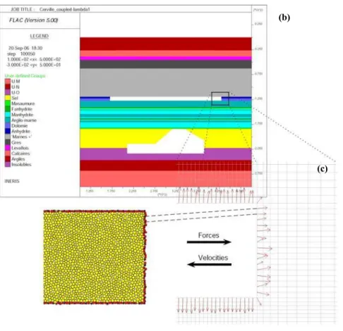
From the previous mechanical laboratory characterization, the competent layer consisting of dolomite exhibits an elastic behaviour accompanied with a brittle failure. The region of interest in terms of expected damage in the dolomite layer was modelled by an assemblage of PFC particles (figure 3c) in order to investigate the damage initiation and propagation processes. That allows us to represent the damage explicitly by the formation and tracking of microcracks. (Hazzard et al. 2000; Potyondy and Cundall 2004). Compared to work of Cai et al. 2007 where the rock mass surrounding an AE sensor modelled using PFC represents a domain of a few millimetres, herein the PFC inclusion modelling will be 8.5 m height and more than 200 m length.
Compared to the preliminary geomechanical model published in 2005, the PFC inclusion is modelled here with a random packing more than a regular hexagonal packing of particles. This aimed to better represent the microcaraking distribution as discussed in Mercerat et al. 2005 from the laboratory tests simulations. In fact, we used a random particle packing of particles of decimetric size to create the discrete inclusion of 260 m by 8.5 m. Consequently a new microproperties calibration has been carried out in order to match the mechanical properties (modules, strengths) of the modelled materials at both the laboratory and regional scale.
To describe the behaviour of the other layers (mainly consisted of marls and salt) which present more ductile and/or viscoplastic behaviour, a continuum approach based on the code FLAC, widely used by the scientific and industrial communities, is employed. This leads to approach more complex rheological behaviours based on continuum mechanics (elastoplastic with or without hardening and softening, viscoelastic or viscoplastic). Hence, the brittle layers are modelled in PFC as an inclusion of bonded circular particles embedded in a classical FLAC grid, the applied forces received from PFC act on the grid points along the inclusion boundary. The translational velocities of these PFC boundary particles are received from FLAC (figure 3c). The full coupling between
FLAC and PFC boundaries is achieved through a special function written in the internal FISH
language.
The geometrical model of the site based on the geological log of the area (figure 3), is essentially composed of :
(a) the salt formation extending from the bottom boundary of the model up to the actual brine cavity roof. The cavity presents a polygonal shape (based on sonar data) that rest fixed throughout the simulations;
(b) on top of the salt layer, a formation of intercalated marls consisted of thin anhydritic to clayley marls with relatively weak mechanical characteristics;
(c) the overburden characterized by the competent layers (Beaumont dolomite and anhydrite level; to simplify, the two competent layers will be assembled into an unique stiff bench), followed by a series of carbonates, sandstones and marls layers up to the surface.
The geomechanical characteristics of the salt, the competent layers and the intercalated marls are known from the laboratory tests, whereas the characteristics of the other materials are chosen according to the literature concerning the regional geological basins (Nothnagel, 2003).
In a first time and in order to define appropriate model size and boundary conditions with regard to the cavern size, many simulations have been carried out using also a continuum approach for the competent layer. Finally, the selected geometrical model is 4600 m large and 850 m high (figure 3). Even if there is no symmetry of the cavity, we choose to reduce the 3D problem in 2D for these first calculations. While considering a section in the greatest dimension of the cavity, we place ourselves in conditions of plane strains.
The initial stress state is assumed to be isotropic: this assumption is well justified within the salt layer where null initial deviatoric stress is expected. In absence of data concerning the initial stresses in the other materials, we also admit that they are isotropic. Finally, the vertical stress is equal to the overburden weight. The initial conditions within the PFC inclusion and in the cavity before the exploitation restarts:
(a) within the PFC inclusion, we established a uniform isotropic stress of 3 MPa corresponding to the approximate initial stress found at the inclusion depth (~120 m) due to the overburden weight.
(b) when the cavity is full of brine, a normal stress acting on the cavity walls equal to λ σ0 is
imposed (σ0 is the overburden weight at the corresponding depth, and λ=0.5). The filling out
process is modelled by progressively reducing λ from 1 (no cavity) to 0.5 (brine filled cavity), and later by reducing the wall pressure down to 0 (empty cavity).
3.3. PFC microproperties calibration
In PFC, the rock mass is modelled as an assembly of bonded circular particles, that can break apart to simulate explicitly a microcrack generation. The particle contact stiffness, the friction coefficient of the contact and the contact bond model between different particles govern the mechanical behaviour of the material. These are known as the microparameters (or microproperties) of the bonded particle model. They must be chosen in order to reproduce the relevant material properties measured in the laboratory tests of the rock specimen to be modelled. This calibration process is not specified a priori and a trial-and-error procedure is generally used. Nevertheless there is some knowledge and guidance based on previous research on PFC calibration (Potyondy and Cundall, 2004) about the relation between each microparameter and its effect on mechanical properties (see Table 1). Following this guidance and using the previous laboratory test results, we have calibrated our discrete model of the Beaumont dolomite by simulating a Brazilian test and three biaxial compression tests at 0.1, 2 and 5 MPa of confining pressure (Mercerat et al, 2005). We used a parallel bonded model material because it better approximates the mechanical behaviour of brittle elastic cement joining two bonded particles.
More recently, three-point bending tests performed by Boidin (2007) have been simulated in order to better identify the PFC microproperties. In this case, predicted and measured stress intensity factor (KIC) are compared. Figure 4 shows a simulation of a three-point bending test.
Competent layer (8.5 m high)
Alternation of the marls Alternation of marls, sandstone and limestone
Brine cavity Salt 4600 m 850 m 183 m ρ g h ρ g h (a)
Competent layer (8.5 m high)
Alternation of the marls Alternation of marls, sandstone and limestone
Brine cavity Salt 4600 m 850 m 183 m ρ g h ρ g h (a)
(b)
(c) (b)
(c)
Figure 3. Model of Cerville-Buissoncourt site : (a) geometry and loading, (b) geometry of continuum (FLAC) domain, (c) assembling of PFC particles that models a part of dolomite layers
Figure 4. Force distribution in the cement between particles : tensile/compression (red/black) : tensile cracks (yellow)
Table 1. Relations between microproperties and mechanical properties.
Microproperties Mechanical properties
Normal (kn) and shear (ks) contact stiffness Young’s modulus (E) and Poisson’s ratio (ν) Normal (σc) and shear (τc) bond strengths Uniaxial Compression Strength (UCS) Friction coefficient (μ) – Particle clustering
Ratio shear/normal bond strength Slope of failure envelope
4. Results of the large scale numerical modelling of overburden damage 4.1. Verification of the large scale hybrid FLAC-PFC model response
Before building the large scale model with the hybrid discrete-continuum approach, we firstly carried out a modelling of the draining of the cavity with a completely continuous approach (FLAC).
This preliminary continuum modelling made it possible to optimise the lateral extensions of the geometrical model with regard to the large cavity sizes and also to obtain the first responses of ground movement during the reducing the brine pressure. But also, the confrontation of the results of the continuum model with that based on the hybrid approach makes it possible to validate the discrete-continuum geomechanical model shown in figure 3.
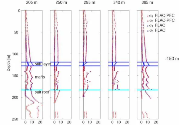
In this section we present a comparison between the continuum and the hybrid models. For that, we compared : (a) the vertical displacement at the surface (subsidence) and the vertical displacements on both sides of the dolomite layer; (b) principal stresses at the base and the top of the dolomite layer. In PFC inclusion, stresses are calculated inside the measurement circles shown in Figure 5. In figure 5, we compare the vertical displacements and principal stresses at different depths obtained by the fully continuum model (using FLAC code) and the hybrid FLAC-PFC model. We can appreciate the results (at a brine depth of 150 m, just before the plasticity onset in the competent bed) showing an almost perfect match between the two approaches.
Figure 6 represents the distribution of stresses within the overburden of cavity. Profiles of the principal stresses in the model section are qualitatively and quantitatively identical between the two approaches.
This validates the size of the large scale hybrid model, the calibration of the microproperties realized to reproduce the elastic mechanical properties of the assemblage of PFC particles, but also the extension and initial conditions (in terms of stresses) applied in inclusion.
Measurement circles (PFC)
Measurement circles (PFC)
Figure 5. Locations of vertical and horizontal profiles used for analysis
Figure 6. Profiles of vertical displacement at three different depths (0 m, 127.5 m and 139 m) and principal stresses at -127.5 m (base of Beaumont dolomite) and -125.5 m (inside the Beaumont dolomite
Figure 7. Major and minor principal stresses (brine depth of 150 m) : comparison between continuum and hybrid approaches
4.2. Hybrid FLAC-PFC model for different brine levels (>150 m)
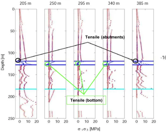
Figure 8 illustrates the distribution of principal stresses along five vertical profiles (from the cavity bottom towards the ground surface) for a brine depth of 160 m : this level corresponds the failure onset in the competent bed. Examination of stresses in the stiff layer (delimited by blue horizontal lines), we can observe that tensile failure occurs : (a) on the top of the dolomite layer at the abutments (top fibre); (b) at the bottom fibre in the central part over the cavity.
As long as the brine level does not exceed the depth of 160 m, there are no developments of microcracks : microcracking remains diffuse in the dolomite layer (Figure 9). The concentration of the forces is not very clear yet, even if we can notice the development of a zone in tension at the central region of inclusion with respect to the abutments (Figure 8).
Starting from 165 m (0.22 MPa of brine pressure at the roof of cavity) we note a coalescence of the microcracks in two zones located at the abutments (top fibre of dolomite bench). When reducing the brine pressure to 0.16 MPa (or 170 m), microcracks coalescence appears in the central part at the base of the competent layer.
This is in conformity with the traditional results of the strength of the materials theory which indicate that tensile failure of a fixed beam initially appears at the location of abutments in the top fibre of beam, then to the centre of the beam in bottom fibre; say, primary the behaviour of a fixed beam accompanied to that of a simple beam (Diederichs et al., 2004).
After this stage, for a level of brine of 170 m, microcracks coalescent at the base of the bench and macroscopic fractures start to be propagated upwards. System equilibrium is not reached any more beyond the level of brine of 165 m. The grounds of overburden located above the cavity move to the vacuum, indicating a numerical instability which could correspond to the initiation of a brutal collapse.
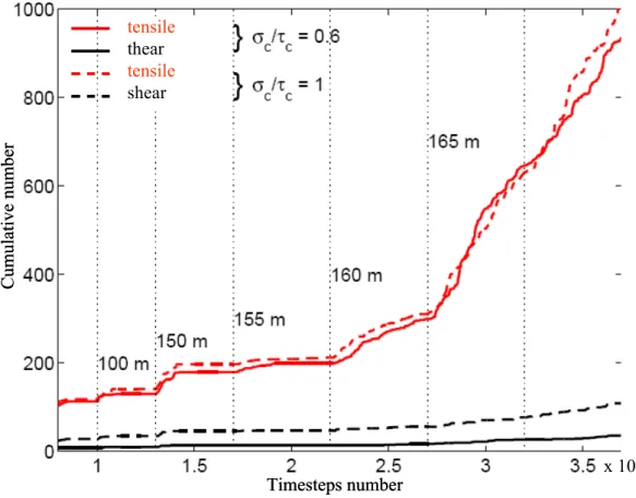
Another way of highlighting this instability, for a brine level folded back around 165 m, was the analysis of the numbers of microcracks generated in the dolomite layer during the folding of the brine level. Figure 10 shows a clear increase in the number of the microcracks as soon as the brine pressure at the roof of the cavity is lower than 0.22 MPa (or depth of 165 m). This type of change was observed in simulations with PFC of the laboratory tests, and indicates the creation of one or more macrofractures (inducing significant and abrupt increase in the acoustics emission) which involve the total loss of sample strength (Diederichs et al., 2004; Potyondy and Cundall, 2004). This abrupt increase of the microcracks number can thus be correlated with an acceleration of the microsismic activity.
In Mercerat et al. 2005 based on several simulations of the biaxial and Brazilian tests it was pointed out the difficulty to simultaneously calibrate both tensile and compressive macroscopic strengths with a simple PFC models. The main part of the failures awaited in the stiff layer of dolomite being in tension, we privileged the reproduction of the macroscopic tensile strength of dolomite. That led us to the ratio c/ c of 0.6 ( c/ c = 15 MPa/25 MPa, c and c ared defined in Table 1).
However, we wondered about the consequence of such a choice on the generation of the acoustic emissions, since such a ratio value would rather favourite cracks in tensile than in shear (Hazzard and Young, 2002). Thus, a simulation with an increase in the ratio c/ c from 0.6 to 1 was
undertaken with the objective to clarify the impact of strengths ratio. This complementary simulation led to a spatial distribution of the microcracks very similar to that presented in figure 9, the only difference being the number of shear microcracks slightly more significant appearing in the bench of dolomite (figure 10). The number of shear microcracks remains marginal compared to that of the microcracks in tension mode. In both cases ( c/ c = 1 or 0.6), the microcracks are however
mainly in tension (less than 10 % of microcracks in shear).
Tensile (bottom)
Tensile (abutments)
Tensile (bottom)
Tensile (abutments)
Brine level :
Tensile cracks occuring at the abutments of competent layer
Tensile cracks occuring at the bottom
Brine level :
Tensile cracks occuring at the abutments of competent layer
Tensile cracks occuring at the bottom
Figure 9. PFC inclusion at different stages of the cavity filling out (brine level 155 m down to -170 m). Bond forces in tension/compression (red/nblack). Microcracks in tension/shear (yellow/cyan)
x 105 Timesteps number Cumulative number tensile thear tensile shear x 105 Timesteps number Cumulative number tensile thear tensile shear
Figure 10. Cumulative number of microcracks in the PFC inclusion. Vertical lines correspond to different stages (brine level depths). Microcracks in tension/shear (red/black). More than 90 % are tensile cracks
5. Conclusion and perspective
A local seismic network has been installed and further calibrated in the site test of Cerville-Buissoncourt (Lorraine, France). This site has been chosen by the GISOS working group to test and validate some monitoring techniques that could be used in the future in other salt mine environments, and not to pronounce about the consequences, in terms of environmental impact or security, of some specific salt exploitation methodology implemented in the test site.
We have presented a methodology of a hybrid numerical modelling approach to analyse a complex geomechanical and geophysical process in a salt mine-environment. This involves the fracturing and deformation of the overburden due to the brine pumping out and the consequent pressure decrease in an underground cavity.
A hybrid numerical modelling approach FLAC-PFC has been implemented for the specific site test of Cerville-Buissoncourt. The validation/calibration of the hybrid large scale model is achieved by comparing, at the site scale, the elastic response of the discrete inclusion and the response from the fully continuum approach. The results are quite satisfactory. Moreover, the development of microcracking is in accordance with the predicted tensile zones obtained with a fully continuum approach. The sudden rise up of the microcracks cumulative number from a specific brine depth level on, can be interpreted as the fracture development by coalescence of microcracks within the competent bed, which may possible, indicate the beginning of a generalized instability of the overburden. From both continuum and hybrid approaches, the main fractures in the competent layer are tensile. Finally, the coupled continuum-discrete methodology presented herein provides a good opportunity to explicitly simulate the microcraking in the overburden. A conclusive statement about failure mechanisms, with eventually a quantitative comparison, will be achieved when information about microseismic event locations and magnitudes will be available.
Next stage of this work is firstly to back-analyse the transient pressure experiment in order to validate the proposed methodology, and secondly, to compare these numerical modelling results with those of the measurements recorded in situ after restarting of salt exploitation in a few months
6. Acknowledgements
This work is performed within the GISOS project. We acknowledge with gratitude the financial support of the French Ministry in charge of Industry. The authors also thank the company SOLVAY S.A. for the site, the technical support and the data for site characterization.
7. References
Boidin E. (2007) Interactions roches/saumures en contexte d’abandon d’exploitations souterraines
de sel. Thèse de doctorat, LAEGO, Institut National Polytechnique de Lorraine, France.
Cai M., P.K. Kaiser, H. Morioka, M. Minami, T. Maejima, Y. Tasaka, H. Kurose (2007).
FLAC/PFC coupled numerical simulation of AE in large-scale underground excavations, Int. J
of Rock Mech. and Min. Sciences, Vol. 44, 550-564.
Diederichs M., P. Kaiser et E. Eberhardt (2004) Damage initiation and propagation in hard rock
during tunnelling and the influence of near-face stress rotation, Int. J of Rock Mech. and Min.
Hazzard J. F., Young R. P., Maxwell (2000). Micromechanical modelling of cracking and failure in
brittle rocks, J of Geophysical Research, Vol 105, 37555-37569.
Johnston J. C., Einstein, M. H. (1990) A survey of mining associated seismicity; Proc 2nd Int Symp Rockbursts and Seismicity in Mines, Minneapolis, Fairhurst (ed), Rotterdam:, A.A. Balkema, 121-127.
Kemeny JM, NGW. Cook (1987) Crack models for the failure of rock under compression, Proc. Second Int Conf Cons Laws Eng Mater 1987;2:879–87.
Mendecki A. J., (1997). Seismic Monitoring in Mines, Chapman and Hall, London, UK.
Mercerat D, Driad-Lebeau L., Bernard P and Souley M. (2007) Induced seismicity monitoring of an
underground salt cavity under a transient pressure experiment, Solution Mining Research
Institute (SMRI) – Spring 2007 Conference, 29 April- 2 May, Basel, Switzerland.
Mercerat D., Souley M., Driad-Lebeau L., Bernard P. (2005). Induced seismicity in a salt mine
environment evaluated by a coupled continnum-discrete modelling, Post-Mining 2005,
November 16-18, Nancy, France.
Nothnagel R. (2003). Modélisation des instabilités dans Mécanique des Roches : application à
l’exploitation de la concession de Drouville. Thèse de Doctorat, École des Mines de Paris.
Potyondy D, Cundall P. (2004). A bonded particle model for rock. Int. J of Rock Mech. and Min. Sciences, Vol. 41, N°8, 1329-1364.
Potyondy D.O. (2007) Simulating stress corrosion with a bonded-particle model for rock, Int. J of Rock Mech. and Min. Sciences, Vol. 44, 677–691.
Zhu Q., Kondo D., Shao J., Pensee V. (2008) Micromechanical modelling of anisotropic damage in brittle rocks and application, Int. J of Rock Mech. and Min. Sciences, accepted for publication.