HAL Id: hal-01753221
https://hal.archives-ouvertes.fr/hal-01753221
Submitted on 1 Jul 2020
HAL is a multi-disciplinary open access archive for the deposit and dissemination of sci-entific research documents, whether they are pub-lished or not. The documents may come from teaching and research institutions in France or abroad, or from public or private research centers.
L’archive ouverte pluridisciplinaire HAL, est destinée au dépôt et à la diffusion de documents scientifiques de niveau recherche, publiés ou non, émanant des établissements d’enseignement et de recherche français ou étrangers, des laboratoires publics ou privés.
Arnaud Vena, Etienne Perret, Darine Kaddour, Thierry Baron
To cite this version:
Arnaud Vena, Etienne Perret, Darine Kaddour, Thierry Baron. Toward a Reliable Chipless RFID
Humidity Sensor Tag Based on Silicon Nanowires. IEEE Transactions on Microwave Theory
and Techniques, Institute of Electrical and Electronics Engineers, 2016, 64 (9), pp.2977 - 2985. �10.1109/tmtt.2016.2594229�. �hal-01753221�
Abstract—This paper presents a chipless RFID sensor tag
having both identification and sensing capabilities. It is based on one resonant scatterer operating as a signal processing antenna in the 3 to 7.5 GHz band. The scatterer is used to monitor a physical parameter variation, as well as to identify the remote sensor. To make a resonator sensitive to the humidity, silicon nanowires are deposited on the tag surface using a simple process. The tag needs only one conductive layer so that it can be directly printed on the products to sense and to identify. Measurements done using a bistatic radar configuration in the frequency domain validate this concept. To demonstrate the reliability of such an application, two chipless RFID sensors placed in various environments are simultaneously detected using an anti-collision technique based on spectral separation.
Index Terms—Chipless, RFID, Sensor, Humidity, Silicone
Nanowire, Anti-collision.
I. INTRODUCTION
ENSING a physical parameter remotely is required in numerous monitoring applications such as weather station, or sensor networks. Using the passive RFID technology for these applications could be interesting because it doesn’t need to be powered by a battery cell since energy is directly extracted from the EM field of the reader [1-5]. This gives a key advantage to sensor RFID technology because maintenance of remote sensor is largely reduced.
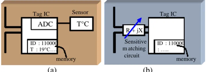
To detect a physical parameter variation in classical RFID, additional discrete components providing a voltage output proportional to a physical parameter, such as temperature or gas concentration, are needed. The signal obtained from these dedicated sensors is then sampled by the chip and stored into a register as shown in Fig. 1 (a) [1]. More recently UHF RFID chip with integrated sensors are available on the market [6]. In contrast, to reduce the sensor – tag cost, other techniques much simpler based on the measuring of the backscatter power (in magnitude or phase) at receiving reader antenna or
Manuscript received September 22, 2015.
A. Vena, is with the Université of Montpellier, e-mail: [email protected]. E. Perret and D. Kaddour are with the Laboratoire de Conception et d’Intégration des Systèmes (LCIS) - Grenoble Institute of Technology, Valence, France ([email protected]; [email protected]). E. Perret is also with the Institut universitaire de France, Paris.
T. Baron is with the Laboratoire des Technologies de la Microéletronique (LTM / CNRS), Grenoble, France. France (e-mail: [email protected]).
the threshold transmitted power of the tag (see Fig. 1 (b)) are introduced [3], [4], [7-10]. In this case, the antenna is made sensitive to one of the environment parameters, such as temperature [3], humidity [8-10] or a mechanical stress to detect a strain [11].
However, such very simple RFID sensor tags are still not implemented in real applications. Indeed, the large scale production of these sensors is inhibited by the lack of high sensor-to-sensor reproducibility.The major limitation of these RFID sensor-tags without dedicated sensors comes from the variability of the chip’s response. Indeed for these very low cost sensors, where the detection is based on the transmitted activation power or the backscattered power at the receiving antenna, a strong versatility is generally observed concerning the threshold power of the chips as well as the connection between the chip and the antenna. Moreover, a RFID chip is a quite complex electrical component, that is to say nonlinear, and frequency dependent. All these aspects have to be taken into account to realize accurate sensor measurements. Consequently, with such an approach, making a RFID sensor tag without dedicated sensors but with a repeatable behavior is a hard task.
Chipless RFID technology have given a new paradigm in the field of RF identification [12]. A chipless tag doesn’t embed any silicon chip so that no classical modulation scheme is needed for communication. Instead, simply its EM signature, from a radar point of view, is used to extract a unique ID [2], [13-15]. The two major strengths of chipless RFID tags are their unit cost, which could be very low [16], [17] and their high levels of reliability even if they operate in harsh environments [15], [18]. As in classic RFID, the issue of integrating a sensor function to chipless RFID has been
Towards a reliable Chipless RFID Humidity
Sensor tag Based on Silicon Nanowires
Arnaud Vena, Etienne Perret, Senior Member, IEEE, Darine Kaddour, and Thierry Baron
S
ADC T°C ID : 110000 T : 19°C….. Tag IC Sensor memory (a) ID : 110000 : ….. Tag IC memory (b) R + jX Sensitive m atching circuitFig. 1. RFID sensor using (a) classical passive or active approach with dedicated sensor components, (b) without dedicated sensor components. In the latter case, the sensitive matching circuit can be easily obtained by adding a sensing material directly upon the tag antenna. This principle can also be used in chipless RFID.
functionalities such as sensing can be implemented into a chipless RFID [19-25], allowing to differentiate this technology from barcode. Contrary to conventional RFID sensors, the major advantages of chipless RFID sensors are their potential to have a good sensitivity and repeatability and of course an incomparable lifetime. In the literature, it can be found some chipless sensors able to detect gases. Among them, we can find ethylene gas sensor [19], NOx gas sensor using a CNT (Carbon NanoTube) deposit [20] or hydrogen chipless sensor based on a surface acoustic wave substrate [21]. In [22], the use of a resonator for which the resonant frequency is correlated with the temperature is presented.
Besides, in the state of the art, silicon nanowires (SiNWs) have shown a strong sensitivity to humidity [26] and temperature variations [27]. One of the first totally integrated chipless tag-sensors, with remote (wireless) reading of the identifier and the value to be measured, was experimentally validated in [24]. By chipless tag-sensor, we mean a compact chipless tag with identification and sensor functions that are totally integrated and compatible with the spirit of chipless RFID (that is, simple in design and low in cost, as well as potentially fully printable, similar to barcodes in that there is no discreet element connected to the tag). Silicon nanowires have also been used to realize humidity sensors based on retransmission chipless tags encoding information with group delay variations. However, the reproductively and repeatability study, which is crucial for sensing has never been addressed for this type of extremely low cost fully printable sensor tags.
In this work, a small deposit of SiNW is placed on one of
sensor. The basic idea is to monitor its resonant frequency, which becomes significantly dependent to the humidity variation [24-26]. The data is encoded in the frequency domain using a classical frequency shift encoding [14]. As a result, with only four resonators, a coding capacity of 13 bits is achieved within a small surface (6x2.5 cm²). As for [19], the tag could be directly printed on an object since only one conductive layer is needed for realization. Moreover the deposition process of silicon nanowires (melted in a solvent) is very basic and can be realized with classical inkjet printer, together with the conductive pattern deposit. It is why very low cost chipless sensor tags with a large coding capacity can be performed.
Even if the literature concerning chipless RFID sensors is growing, only few works have demonstrated a real wireless measurement of the chipless sensor remotely or the presence of a sensor and ID function together inside a tag. Moreover, to the author’s knowledge, there is no work focused on the evaluation of the repeatability of chipless tag sensing measurement. We will show that contrary to RFID sensors based on the same idea (fully analogic tag, without dedicated sensors component), a very good repeatability could be obtained with these homemade chipless sensor tags. This also suggests that such type of sensor tags, realized with automatized process would present higher performances. These points will be developed in details in the following parts.
II. CONCEPT AND APPLICATIONS
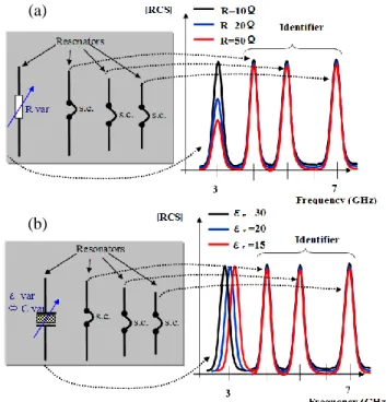
In chipless RFID, the only way to detect a physical parameter variation and consequently modify the EM response of a tag consists in using some sensitive materials providing variable conductivity, permittivity or permeability. A change in conductivity will induce a variation on the tag response level while a change in permeability or permittivity will affect the resonant frequency or the phase of the scatterer. Finally, from the reading system point of view, a chipless RFID tag can be seen as multiple antennas loaded with complex load as shown in Fig. 2 (a) an (b). For a chipless sensor tag, one of these loads has to be sensitive to a (a)
(b)
Fig. 2. Principle of a chipless RFID sensor tag based on the supervision of
(a) conductivity variation, (b) effective permittivity variation. Fig. 3. Microscopic image of silicon nanowires deposited upon classical RF substrate. The arrow represents a dimension of 20 µm.
physical parameter variation while keeping the other ones constant to encode a specific ID. Fig. 2 (a) presents the frequency response of a chipless RFID sensor tag for which the resonant peak at 3 GHz is sensitive to the surrounding material resistivity. The coding resonators consist of shorted dipoles of various lengths while the sensor is made of a dipole loaded by a variable resistance. The resistance variation produces a change in the reflected power. On the contrary, when only the imaginary part of the load is modified, a resonant frequency shift is observed as shown in Fig. 2 (b). In this last case, the load could be a capacitor made by a dielectric for which the permittivity is sensitive to the physical parameter to measure. Since there is no transmission protocol, simultaneous detection of several chipless sensors is a hard task. However, each EM signature could be discriminated in frequency domain using spectral separation or in time domain using gating if sensors are sufficiently separated.
III. SILICON NANOWIRE BASED CHIPLESS SENSOR
A. Silicon Nanowires Behavior
Concerning the sensing resonator, its resonant frequency have to be linked to the sensitive material and not to a change in the geometry of the scatterer as it is the case for the other resonators who are encoding the ID. However this frequency variation has to be linked to a physical parameter. For this, a specific sensitive material should be used. In this work, the material under consideration is able to change its electrical properties depending on the humidity. It can be found in the state of the art that SiNWs make a good candidate to achieve this goal [26], [27]. For this work, the SiNWs have been elaborated by catalytic Chemical Vapor Deposition (CVD) [28]. Typical scanning electron microscopy picture of the fabricated nanowires is presented in Fig. 3. The deposition process is compatible with printing techniques since nanowires can be melted with a solvent that evaporates at ambient temperature. Thus to make one of the sensitive resonator, drops containing nanowires are deposited directly on the metallic strip in the area where the electric chipless sensor probe water Hygrometer / Thermometer (TES-1365) (a) (b) (a) (b)
Fig. 6. Measurement set-up for hygrometry variation. (a) View of the box front of the antennas. (b) Photo of the inner box containing the probe and the chipless sensor under test. The water level is about 1 cm.
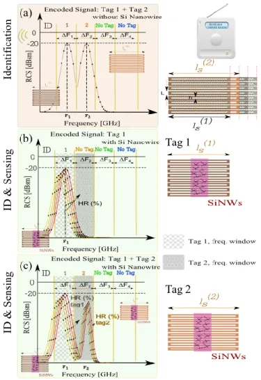
Fig. 4. Chipless RFID tag with sensing capability: principle of anti-collision technique based on spectral separation to handle several sensors at a time. (a) Frequency windows associated to each tag. (b) Relative Humidity (RH) effect on the resonant frequency of tag 1 interrogated separately. (c) Relative Humidity (RH) effect on the resonant frequency of tag 1 and 2 interrogated at the same time.
Fig. 5. (a) Multiple coupled loops resonator geometry, (b) distribution of the Electrical field on the resonator at the resonance frequency. The length of the resonator is equal to ls = 34 mm and the resonant frequency is close to 3.3
evolves, SiNWs electrical properties change (nanowires capture water molecules, and the effective permittivity is locally modified [26]) so that the field lines are rearranged around the resonator and a small frequency shift can be observed. If we focus on the frequency deviation observed in [10], one can notice that if the relative humidity decreases, the frequency rises. The phenomenon behind this behavior could be understood by the following explanation. With less water molecules, the effective permittivity due to a mixture between air, dielectric and water is lower. Therefore, the resonant frequency rises. Besides, in the state of the art, some experiments revealed a sensitivity of the silicon nanowires to the temperature due to a conductivity change [27]. In our case, such a variation was not observed since we didn’t notice a strong contrast concerning the magnitude of the resonant peak.
B. Chipless Sensor Design
For the chipless tag, we seek to design a scatterer with a quality factor as high as possible to increase the sensitivity to a permittivity change of the material. This scatterer is intended to have a large enough RCS value to be properly detected by the reading system. These constraints leaded to the design of the tag presented in Fig. 5 (a). It is based on several squared loops with the same dimensions placed close to each other. The quality factor of the overall resonator is controlled by the distance between loops whereas the RCS magnitude depends on the number of loops. The wire width (L-h)/2 is thin (250 µm) allowing a high quality factor. The main difference between the behavior of one bigger squared loop resonator and the proposed resonator is the level of the structural mode of reflection which is lower in this case and allows a better detection. As a result, compared to the tag used in [24], the selectivity is increased. The use of several identical loops allows increasing the RCS level at the resonant frequency.
C. RF measurements
The experiment firstly introduced in [10] has been used to detect the sensitivity of the new chipless sensor tag of Fig. 5.
A plastic box partially filled with water has been used. When the box is closed, the relative humidity (RH) rises from the ambient humidity to 100% in half an hour for the used box of size 40x20x30 cm3. The box is placed in front of the two antennas in anechoic chamber as shown in Fig. 6 (a). The two antennas are directly connected to the VNA. The sensor is put inside the box as shown in Fig. 6 (b). To supervise, the value of the RH and the temperature during the measurement cycle, a probe connected to a hygrometer/thermometer is inserted inside the box. The calibration technique used is explained in details in [14]. The measurement of the empty chamber and a known reference object is done before any sensor measurement. Fig. 5 (b) shows the electric field distribution at the resonance. We notice that the maximum value is located in the middle of the loop, so it is why the deposition of silicon nanowires N doped is located in this area as shown in Fig. 7. We realized four tags having the same dimensions as shown in Fig. 7 to evaluate the reproducibility of the fabrication process. Additionally, we limited the sensitive area to a surface of 0.4 x 1.3 cm². The nanowires mixed in alcohol solutions, are manually deposited in the center of the scatterer, with the help of a micropipette. The alcohol evaporates at ambient temperature, whereas the nanowires remain fixed on the scatterer. We observed in each case a random distribution of nanowires within the specified area (see Fig. 3).
The curves plotted in Fig. 8, show the evolution of the frequency shift as a function of the time for a multiple coupled loops resonator of length ls = 34 mm and height H =
12 mm. To correlate this result with the humidity, we superimposed the value recorded using a hygrometer TES-1396. During this measurement cycle, the temperature is controlled to be constant. The temperature has been recorded
3.24 3.26 3.28 3.3 3.32 3.34 3.36 3.38 3.4 -55 -50 -45 -40 -35 Frequency [GHz] R C S ( d B s m ) 76 78 80 82 84 86 88 90 92 94 96
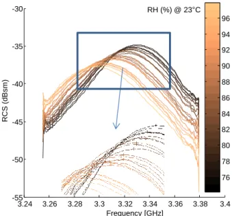
Fig. 8. Recorded frequency responses when the relative humidity rises from 74% to 98%. Zoom in on a portion of the curves showing the maximum of each curve (crosses). The sensor tag used is depicted in Figs. 5 and 7.
Fig. 7. Photos of different realized sensor tags operating at around 3.3GHz having a SiNW deposit located in the middle of the scatterer. The length ls is 34mm according to Fig. 5 (a).
and a very slight variation lower than 0.1°C was noticed. Overall, all the changes observed in measurement results are
due to the strong sensitivity of the SiMWs to the humidity. A frequency shift of 35 MHz (from 3.295 to 3.330 MHz) can be observed from 74 to 98% of RH. The sensitivity is close to 1.5 MHz per 1% of RH. It is clear from Fig. 8 that observed RH changes can be characterized by different approaches. For instance, we can consider the magnitude variation of the RCS for a given frequency (1) (for example the resonance frequency of the tag for a specified value of RH). We can also take into account peek position of each curve (marked by crosses in the zoom of the Fig. 8), and process frequency (2) or magnitude (3) variation of this maximum. These three approaches have been tested; measurements results showed that approaches (1) and (2) exhibit better results. However, technique (2) (see Fig. 8) looks more promising when considering detection reliability as regards as measurement distance and calibration versatility. In the next section, we provide more details regarding reproducibility of these novel sensors.
D. Reproducibility
The measurement process reproducibility is first evaluated. Measurements on the same sample but after having extracted and replaced the sensor tags in the box have been done several times and for some of them several hours after. The
75 80 85 90 95 100 3.295 3.3 3.305 3.31 3.315 3.32 3.325 HR % F re q M a x (G H z ) 75 80 85 90 95 100 -51 -50 -49 -48 -47 -46 -45 -44 -43 HR % R C S (d Bs m ) 4.5dB 4.5dB (b) (c) 3.25 3.3 3.35 3.4 -58 -56 -54 -52 -50 -48 -46 -44 -42 Frequency (GHz) R C S (d B s m ) HR % 80 85 90 95 3.25 3.3 3.35 3.4 -58 -56 -54 -52 -50 -48 -46 -44 -42 Frequency (GHz) R C S (d B s m ) HR % 80 85 90 95 (a)
Fig. 9. Measurement process reproducibility: measurement cycles on the same sample separated by several hours. (a) Typical recorded frequency responses as a function of the time when the relative humidity rises. Only 2 measurement results are shown. (b) RCS magnitude variation at f=3.3325GHz as a function of the recorded RH for 4 measurements cycles. (c) Frequency shift of the maximums of the RCS values as a function of the recorded RH for 4 measurements cycles.
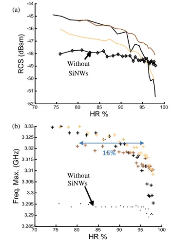
a) 70 75 80 85 90 95 100 -52 -51 -50 -49 -48 -47 -46 -45 -44 HR % R C S (d B s m ) 70 75 80 85 90 95 100 3.285 3.29 3.295 3.3 3.305 3.31 3.315 3.32 3.325 3.33 HR % F re q . M a x . (GH z ) 15% (a) (b) Without SiNWs Without SiNWs
Fig. 10. Reliability of manufacturing process: characterization of three sensor tags with the same SiNWs deposit and dimensions. (a) RCS magnitude variation at f=3.3325GHz as a function of the recorded RH. (b) Frequency shift of the maximums of the RCS values.
results are plotted in Fig. 9. In Fig. 9 (a), we notice a very similar behavior between these runs. Fig. 9 (b) presents the already mentioned case (1), that is to say the variation of the RCS magnitude for a specific frequency. For each measurement a same variation of 4.5 dB is observed for a change of the RH value between 78% and 98%. Only a small constant change in the RCS level differentiates the 4 measured curves. These differences typically correspond to misalignments that can occur during the measurement process between tag, reference objet and the antennas of the reading system. In Fig. 9 (c), the variation of the resonance frequency is studied (case (2)) for 4 different measurements of the same tag. A shift of 25 MHz is observed. The recorded points provide a linear characteristic between the frequency deviation and the RH in the range of 84% to 98%.
After that, to evaluate the reliability of manufacturing process of the sensor tag, three samples having the same dimensions have been realized. A similar deposit of SiNWs in concentration and quantity at the same location (see Fig. 7) has been performed. The extraction of the relationship between the magnitude and the RH variations is done for a given frequency as shown in Fig. 10 (a). Additionally, in Fig. 10 (b) the frequency shift as a function of the RH for the three samples is plotted. For the sake of comparison, we also measured and plotted the relationship obtained for a scatterer with no deposit. In Fig. 10 (a), we notice a similar shape for the three samples except that one of the samples who shows an initial magnitude 1dB below the two others. As observed, the magnitude is decreasing as the RH rises from 75% to 98%. For the reference sample with no deposit, the curve shows a smooth slope with a variation less than 0.8 dB to be compared with the 3.5 to 6 dB difference recorded with the three samples having SiWNs. Moreover, we observe that sensitivity of these three samples is getting higher for high
The frequency shift of the resonant peak shows a much more repeatable behavior between the different samples having sensitive material. The difference with the reference sample is even more important because in this case the curve of this last one shows a flat response meaning that it is not affected at all by humidity variation. With SiWNs a frequency shift from 15 to 35 MHz is obtained. As show in the Fig. 10 (b), a maximum error of 15 % on the RH value is observable. It is why these sensors are not intended to give an absolute value of what is the humidity because the variability between every sample is still too high for some applications. However, they can be used to provide a threshold value as green/red sensor does.
E. Characterization of a SiNW deposit
To extract a model of the sensor, we can use the equation (1) that makes a link between the resonant frequency of a half-wavelength resonator and its physical length ls. If we
redefine the effective permittivity as in equation (2), the term
εeff0 corresponds to the case where there is no deposit while
the term Δεeff(ls,RH) represents the effective permittivity
variation depending on the relative humidity.
eff s
l
c
fr
2
(1) 2 2 2 ) , ( ) ( 04
l
fr
c
s RH l eff l eff s s
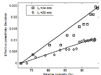
(2)It is interesting to plot in Fig. 11, the effective permittivity deviation Δεeff(ls,RH) as a function of the relative humidity for
two sensor tags of lengths respectively equal to 34 mm and 20 mm. For a 30% of RH variation, the maximum deviation on the effective permittivity is equal to 0.025 and 0.01 respectively for the resonator of length 34 mm and 20 mm. The difference between the two sensor tags could be explained by an electric field strength variation. A probable explanation is the versatility of the deposit between the two sensors. Indeed, the quantity as well as the repartition is not really controlled with the previously described deposition technique. Even thought, this variation range gives us an idea of the frequency deviation that it could be expected for other resonators of length ls.
IV. HANDLING OF TWO SENSORS AT ATIME
For a wireless sensor application, it is often required that more than one sensor can be detected simultaneously. However in the state of the art, the anti-collision topic for chipless RFID tags is rarely discussed. Some techniques are presented in [29] but are best suited for the Surface Acoustic Wave (SAW) chipless tags. The following experiment shows that it is possible to detect two sensors at a time using the technique of anti-collision based on spectral separation [30].
Fig. 11. Effective permittivity deviation as a function of RH for several lengths ls. The initial effective permittivities are respectively equal to 1.752 and
1.494 for the resonator depicted in Fig. 5 (a) of length equal to 34 mm and 20 mm. The curves have been extracted from a humidity measurement cycle described in part III, with the equation (2).
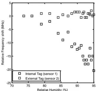
For this purpose, we need to use two resonators having different resonant frequencies. We modify our measurement set-up to insert one resonator inside the box and a second one having a different length, outside the box as shown in Fig. 12. So, only the sensor inside the box could deviates its resonant frequency as the humidity rises. The frequency responses respectively around the resonant peaks of the sensor 1 and 2 are recorded. As the sensor 1 resonating around 3.3 GHz is inside the box, we observe a frequency shift when the humidity rises. Meanwhile, the resonant frequency of the sensor 2 doesn’t change significantly since the RH is quite stable in the anechoic chamber. The extracted curves between the deviation frequency and the RH are shown in Fig. 13. This confirms that two sensors placed in separated environments can be detected simultaneously. To confirm this behavior, we inverted the two sensors and observed that only the sensor inside the box sees its resonant frequency varying.
To extend the concept of the anti-collision based on spectral separation technique to the case where a sensor embeds also an identifier, we have to define the number of frequency positions available. This value depends both on the frequency span and the frequency resolution. If the frequency span considered is UWB (Ultra Wide Band) from 3.1 to 10.6 GHz, we have 7.5 GHz to share between all sensors. For example, if it is needed to handle 100 sensor tags simultaneously, we can assign 75 MHz for each one as shown in Fig. 4. This means that the frequency deviation of the sensor must be lower than 75 MHz. As one can notice, the number of sensor tags that can be handled at a time is a tradeoff with the coding capacity of the tag.
V. CONCLUSION
It was demonstrated that in the case of a single detection, a chipless sensor tag can be realized with only 1 resonator within 3.5x1.5 cm². Since the tag has no ground plane and the sensitive material is deposited by drops at ambient temperature, its realization is fully compatible with printing techniques. The measurement set-up used confirmed the sensitivity of SiNWs to detect a change of the RH by monitoring the resonance frequency deviation on the resonator. A quasi-linear behavior has been observed between the frequency deviation of the sensing resonator and the RH,
and the best sensitivity was found for high RH. Measurements made on the same sample with few hours of delay proved the measurement repeatability, that is a real advantage compared to the passive analog UHF RFID sensor technology. The crucial task of evaluating the reliability of manufacturing process has been done by characterizing several sensors tag fabricated with the same technique. Better repeatability could be obtained with tag produced with automated fabrication process, such as inkjet printing. The measurement of two RFID chipless sensor tags at the same time has been performed using an anti-collision technique based on the spectral separation. This shows the potential of chipless sensors for wireless sensing applications.
ACKNOWLEDGMENT
The authors would like to acknowledge the Grenoble Institute of Technology and the LTM laboratory for their support to this project. The French National Research Agency has supported a part of this project via ANR-09-VERS-013 program.
REFERENCES
[1] K. Finkenzeller, RFID Handbook: Fundamentals and applications
in contactless smart cards, radio frequency identification and near-field communication: Wiley, 2010.
[2] E. Perret, Radio Frequency Identification and Sensors: From RFID
to Chipless RFID: Wiley-ISTE, 2014.
[3] C. Occhiuzzi, S. Caizzone, and G. Marrocco, "Passive UHF RFID antennas for sensing applications: Principles, methods, and classifcations," Antennas and Propagation Magazine, IEEE, vol. 55, pp. 14-34, 2013.
[4] G. Marrocco, L. Mattioni, and C. Calabrese, "Multiport sensor RFIDs for wireless passive sensing of objects—Basic theory and early results," Antennas and Propagation, IEEE Transactions on, vol. 56, pp. 2691-2702, 2008.
[5] G. Marrocco, "Pervasive electromagnetics: sensing paradigms by passive RFID technology," Wireless Communications, IEEE, vol. 17, pp. 10-17, 2010.
[6] S. Manzari, T. Musa, M. Randazzo, Z. Rinaldi, A. Meda, and G. Marrocco, "A passive temperature radio-sensor for concrete
70 75 80 85 90 95 -25 -20 -15 -10 -5 0 5 Relative Humidity (%) R e la ti v e F re q u e n c y s h if t (M H z )
Internal Tag (sensor 1) External Tag (sensor 2)
Fig. 13. Frequency shift as a function of the RH when the sensor 1 of length ls = 34 mm is inside the box.
External sensor 1 Internal sensor 2
Fig. 12. Photo of the two sensors. The internal and the external sensor have a length respectively equal to 20 mm and 34 mm according to Fig. 5 (a).
[7] R. Bhattacharyya, C. Floerkemeier, S. Sarma, and D. Deavours, "RFID tag antenna based temperature sensing in the frequency domain," in 2011 IEEE International Conference on RFID, 2011, pp. 70-77.
[8] J. Siden, X. Zeng, T. Unander, A. Koptyug, and H. E. Nilsson, "Remote Moisture Sensing utilizing Ordinary RFID Tags," in
Sensors, 2007 IEEE, 2007, pp. 308-311.
[9] Y. Jia, M. Heiss, Q. Fu, and N. Gay, "A prototype rfid humidity sensor for built environment monitoring," in International Workshop
on Geoscience and Remote Sensing, 2008, pp. 496-499.
[10] S. Manzari, C. Occhiuzzi, S. Nawale, A. Catini, C. Di Natale, and G. Marrocco, "Polymer-doped UHF RFID tag for wireless-sensing of humidity," in IEEE International Conference on RFID 2012, pp. 124-129.
[11] C. Occhiuzzi, C. Paggi, and G. Marrocco, "Rfid tag antenna for passive strain sensing," in Proceedings of the 5th European
Conference on Antennas and Propagation (EUCAP), 2011, pp.
2306-2308.
[12] S. Tedjini, N. Karmakar, E. Perret, A. Vena, R. Koswatta, and R. E-Azim, "Hold the Chips: Chipless Technology, an Alternative Technique for RFID," IEEE Microwave Magazine, vol. 14, pp. 56-65, July 2013.
[13] S. Preradovic, I. Balbin, N. C. Karmakar, and G. F. Swiegers, "Multiresonator-based chipless RFID system for low-cost item tracking," Microwave Theory and Techniques, IEEE Transactions
on, vol. 57, pp. 1411-1419, 2009.
[14] A. Vena, E. Perret, and S. Tedjini, "Chipless RFID tag using hybrid coding technique," IEEE Transactions on Microwave Theory and
Techniques, vol. 59, pp. 3356-3364, 2011.
[15] A. Vena, E. Perret, and S. Tedjini, "A Depolarizing Chipless RFID Tag for Robust Detection and Its FCC Compliant UWB Reading System," IEEE Transactions on Microwave Theory and
Techniques, vol. 61, pp. 2982 - 2994, 2013.
[16] A. Vena, E. Perret, S. Tedjini, G. E. P. Tourtollet, A. Delattre, F. Garet, and Y. Boutant, "Design of Chipless RFID Tags Printed on Paper by Flexography," IEEE Transactions on Antennas and
Propagation, vol. 61, pp. 5868-5877, 2013.
[17] D. Betancourt, R. Nair, K. Haase, G. Schmidt, M. Bellmann, D. Höft, A. Hübler, and F. Ellinger, "Square-shape fully printed chipless RFID tag and its applications in evacuation procedures," in the 9th
European Conference on Antennas and Propagation (EuCAP'2015), Lisbon, Portugal, 2015.
[18] A. Vena, E. Perret, B. Sorli, and S. Tedjini, "Study on the detection reliability of chipless RFID systems," in 2014 XXXIth URSI General
Assembly and Scientific Symposium (URSI GASS), Beijing, China,
2014.
[19] Y. Li, Z. Rongwei, D. Staiculescu, C. P. Wong, and M. M. Tentzeris, "A Novel Conformal RFID-Enabled Module Utilizing Inkjet-Printed Antennas and Carbon Nanotubes for Gas-Detection Applications,"
Antennas and Wireless Propagation Letters, IEEE, vol. 8, pp.
653-656, 2009.
[20] S. Shrestha, M. Balachandran, M. Agarwal, V. V. Phoha, and K. Varahramyan, "A Chipless RFID Sensor System for Cyber Centric Monitoring Applications," IEEE Transactions on Microwave
Theory and Techniques, vol. 57, pp. 1303 - 1309, may 2009.
[21] W. Jakubik and M. Urbanczyk, "Hydrogen detection in Surface Acoustic Wave gas sensor based on interaction speed," Proceedings
of IEEE Sensors, vol. 3, pp. 1514-1517, 2004.
[22] T. T. Thai, F. Chebila, J. M. Mehdi, P. Pons, H. Aubert, G. R. DeJean, M. M. Tentzeris, and R. Plana, "Design and development of a millimetre-wave novel passive ultrasensitive temperature transducer for remote sensing and identification," in Microwave
Conference (EuMC), 2010 European, 2010, pp. 45-48.
[23] A. Guillet, A. Vena, E. Perret, and S. Tedjini, "Design of a chipless RFID sensor for water level detection " in 15th International
Symposium on Antenna Technology and Applied Electromagnetics (ANTEM), Toulouse, France, 2012, pp. 1 - 4.
[24] A. Vena, E. Perret, S. Tedjini, D. Kaddour, A. Potie, and T. Baron, "A Compact Chipless RFID Tag with Environment Sensing Capability," in IEEE MTT-S International Microwave Symposium
Digest 2012, Montréal (Canada), 2012.
Nanowires," IEEE Antennas and Wireless Propagation Letters, vol. 12, pp. 729-732, 2013.
[26] H. Li, J. Zhang, B. Tao, L. Wan, and W. Gong, Investigation of
capacitive humidity sensing behavior of silicon nanowires vol. 41.
Amsterdam, Pays-Bas: Elsevier, 2009.
[27] C.-P. Wang, C.-W. Liu, and C. Gau, "Silicon nanowire temperature sensor and its characteristic," in Nano/Micro Engineered and
Molecular Systems (NEMS), 2011 IEEE International Conference on, 2011, pp. 630-633.
[28] F. Dhalluin, T. Baron, P. Ferret, B. Salem, P. Gentile, and J.-C. Harmand, "Silicon nanowires: Diameter dependence of growth rate and delay in growth," Applied Physics Letters, vol. 96, p. 133109, 2010.
[29] C. Hartmann, P. Hartmann, P. Brown, J. Bellamy, L. Claiborne, and W. Bonner, "Anti-collision methods for global SAW RFID tag systems," in Ultrasonics Symposium, 2004 IEEE, 2004, pp. 805-808 Vol.2.
[30] E. Perret, R. S. Nair, E. B. Kamel, A. Vena, and S. Tedjini, "Chipless RFID Tags for Passive Wireless Sensor Grids," in 2014 XXXIth
URSI General Assembly and Scientific Symposium (URSI GASS),