HAL Id: hal-01358702
https://hal.inria.fr/hal-01358702
Submitted on 1 Sep 2016
HAL is a multi-disciplinary open access
archive for the deposit and dissemination of
sci-entific research documents, whether they are
pub-lished or not. The documents may come from
teaching and research institutions in France or
abroad, or from public or private research centers.
L’archive ouverte pluridisciplinaire HAL, est
destinée au dépôt et à la diffusion de documents
scientifiques de niveau recherche, publiés ou non,
émanant des établissements d’enseignement et de
recherche français ou étrangers, des laboratoires
publics ou privés.
Using SystemC Cyber Models in an FMI Co-Simulation
Environment
Stefano Centomo, Julien Deantoni, Robert de Simone
To cite this version:
Stefano Centomo, Julien Deantoni, Robert de Simone. Using SystemC Cyber Models in an FMI
Co-Simulation Environment: Results and Proposed FMI Enhancements.
19th Euromicro
Con-ference on Digital System Design 31 August - 2 September 2016, Aug 2016, Limassol, Cyprus.
�10.1109/DSD.2016.86�. �hal-01358702�
Using SystemC Cyber Models in an FMI
Co-Simulation Environment:
Results and Proposed FMI Enhancements
Stefano Centomo
Dipartimento di Informatica, Universit`a di Verona, [email protected]
Julien Deantoni
Universit´e Cˆote d’Azur, CNRS, I3S, Inria AOSTE team, France
Robert de Simone
Universit´e Cˆote d’Azur, Inria AOSTE team, France
robert.de [email protected]
Abstract—The development of Cyber Physical Systems (CPS) requires to model both the cyber (i.e., digital) parts, the physical parts and the interaction between them. The state of the practice in such domain usually involves different stakeholders, which use dedicated modeling languages tailored syntactically and semantically to their domain. Functional Mock-up Interface (FMI) is a recent standard, which provides technical facilities to enable the co-simulation among the different dedicated modeling languages. In this context, this paper investigates how discrete-event models of the cyber part are supported by FMI standard for co-simulation. Two main results are presented: 1) how SystemC models can be integrated into the FMI environment and 2) FMI limitations for the efficient use of discrete-event models in co-simulation. Both results are illustrated by using a simple but illustrative use case mixing models in SystemC (for the cyber part) and Modelica (for the physical part).
I. INTRODUCTION
Cyber-Physical systems become more and more complex. A major characteristic for the simulation of such systems is the mix of discrete-event models for the cyber part and dense/continuous time models for the physical part. With the growing complexity of CPS, different stakeholders are usually involved in their development. These stakeholder can use a language specifically tailored for its domain. However, this approach leads to a mix of heterogeneous models whose simu-lation requires to specify the interaction/coordination between these models [1].
Recently, FMI [2] appeared as a co-simulation standard to make different executable models (denoted as FMU for Functional Mock-up Units) working in a coordinated way. FMI was designed to support the coordination of equation based models, either discrete or continuous. They defined an application programming interface and two operational modes, i.e., model exchange and co-simulation [2]. This paper focuses on the co-simulation mode where each model is simulated independently by its own solver and a master algorithm is used to convey data and ensure time consistency between the different models/simulators at specific discrete time points. In this mode, the simulation is time driven, meaning that the internal state of a model under simulation can only be queried at specific time points (named communication points). It fits correctly the semantics of many persistent signal-based models (e.g., Ordinary Differential Equations or some discrete
equation model for controllers). However it currently does not support well some kinds of cyber models for digital hardware or communication systems where a discrete-event simulator is used (e.g., SystemC (http://www.systemc.org/home) models or network models written in NS-3 (http://ns3project.com/ ns3-simulator/) or SCNSL [3]). There exist different studies on the use of SystemC or other discrete-event languages in FMI co-simulation [4], [5], [6], [7], [8], [9], [10]. Many of these studies focused on how to make cyber models actually working in interaction with physical models. However the details of why and how the cyber models communicate through FMI are usually not given. When these details are given, the approach somehow explains how to force the required semantic adaptation instead of pointing some shortcomings of FMI.
This paper addresses how the FMI standard can support discrete-event cyber models (written in SystemC) for co-simulation. Our goal was to understand to what extend FMI is suitable to be used with such models. Towards this goal, we realized an automatic export of SystemC design specification in FMI. Then we co-simulated a specific SystemC design together with a simple physical model written in Modelica (https://www.modelica.org/). Based on these experiments, we found some shortcomings of the FMI standard, which forbid writing an efficient master algorithm. These shortcomings are mainly concerned with discontinuities both in time and value, which exist in most cyber models. Also from these experiments, we believe it could be interesting to allow not only a pure driven master algorithm but a mixed time-and event-driven master algorithm.
The paper starts with some useful reminders about the FMI and SystemC standards in Section II. Then, the export from SystemC to FMI is detailed, together with the adopted restrictions and choices (Section III). Based on this export, we explain some experiments based on the co-simulation between SystemC and Modelica models. We show timing results in different conditions, helping understand why and when performance issues can arise (Section IV). Then, FMI limitations are explained, together with some proposition to overcome them (Section V). Finally, after a positioning of our approach compared to existing work in Section VI, we
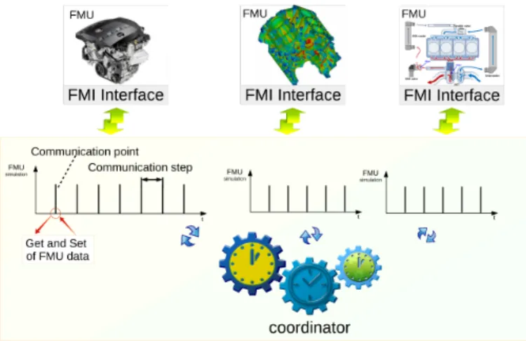
Fig. 1. State-of-the-art approach for co-simulation of a heterogeneous system. conclude and sketch some future works in Section VII.
II. BACKGROUND ONFMIANDSYSTEMC
In this paper we are using the FMI 2.0 standard as co-simulation environment and SystemC to specify the cyber models. Both FMI and SystemC are introduced in this section. FMI is a tool-independent standard framework to support co-simulation of dynamic models. The FMI standard is man-aged and developed as a Modelica Association Project. FMI provides a standardized interface allowing different executable models (named FMU: Functional Mock-up Unit) to be con-trolled by an external software. FMI supports two closely related time-driven control modes, i.e., model exchange and co-simulation. In the context of this paper, the co-simulation mode is targeted. In co-simulation mode, the data exchange be-tween subsystems is restricted to discrete-time communication points. In the time between two communication points (i.e., during a communication step), the subsystems are solved inde-pendently by each FMU simulator. A “coordinator” controls data exchange between subsystems and the synchronization of all simulation solvers by choosing the communication step size (see Figure 1). The coordinator is not part of the FMI standard. The most common coordinator algorithm runs each FMU for a fixed communication step size and collects the outputs from all subsystems. Then, it evaluates the subsystem outputs and distributes them to the FMU of interest. Finally, it continues the (co-)simulation for the required simulation time. Technically, a FMU is a zip archive that contains two main files: 1) a dynamically-loadable library implementing the model simulation and providing the C-language FMI API, and 2) an XML description of the model interface. The model description file follows a specific XML schema defined by the standard, which contains all the information about the input and output variables of the model. These variables, named “exposed variables”, define the communication channels be-tween the FMU and the coordinator. For each variable, it defines its direction (e.g., input, output or parameter), its type among Integer, Boolean, String and Real (respectively named Fmi2Integer, Fmi2Boolean, Fmi2Real and Fmi2String) and an identifier, which is unique for a specific data type: the value reference. In the co-simulation mode, the coordinator can set
or get the current value of an exposed variable (according to its direction) by using the standardized FMI API at specific communication points. This API is also used to simulate the model for a specific interval of time slice by specifying a start/end time (doStep method). In the co-simulation mode, the FMU solver decides how many computational steps should be done by the FMU in those time interval to reach the desired precision. Another interesting FMI feature is the possibility for an FMU to reject a proposed step size if an internal important action occurred during the step computation. In this case the FMU returns its actual time to the coordinator, which can get or set the FMU exposed variables. Based on the FMI standard, we aim at studying how cyber models and, specifically, SystemC digital hardware models can be used for co-simulation.
SystemC is a hardware description language, meant to represent circuits and SoCs at various levels of abstraction (in particular at RTL and TLM levels). Since it is a library designed as an extension of C++, it benefits the data types and compiler environments from this host language. It adds provi-sions for components (modules), ports, parallel threads, signal wires, clocks, timing features, low and high level communi-cation mechanisms. These extensions are semantically dealt with by a non-preemptive scheduler for simulation. Simulation goes through different phases. First, the elaboration phase instantiates the parallel components and their static network (i.e., the sc modules and their interconnects). Then the actual evaluation/update cycle takes place, executing the individual components according to the scheduler policy. Simulation itself can be untimed (causal), cycle-accurate, or loosely timed. In this paper we consider timed designs. The SystemC kernel relies on a discrete-event simulator where time-stamped events are put in a queue and processed in time order. The time between two successive events in the queue can be arbitrarily long. To simulate a SystemC design we need to bind its input and output ports to another component named test-bench. The main role of the test-bench component is the stimulation of the design and the verification of resulting outputs. Consequently its interface is the mirror of the design interface; the input ports of the design are output ports for the test-bench and vice versa. This SystemC library provides a tracing mechanism based on the Value Change Dump format (VCD), defined by the IEEE Standard 1995 and extended in the IEEE Standard 1364-2001. It generates a VCD file with the entire history of the traced ports/signals of the design.
III. EXPORTINGSYSTEMC RTLDESIGN ASFMUS SystemC can be used to specify cyber models at different abstraction levels, ranging from transactional un-timed to cycle-accurate levels. As a first step, because FMI is time driven, we deal with the export of legacy SystemC RTL models written with the SystemC reference library implementation (http://www.systemc.org/downloads/standards/systemc). In or-der to export an FMU from a SystemC RTL design, several steps are required (see Figure 2). All these steps are fully automated, making the creation of an FMU transparent to
Fig. 2. The required steps to export a SystemC RTL design as FMU. the user. The first step consists in extracting the list of all the exposed variables from the SystemC design specification. SystemC is a component based language where a component (module) exhibits some input and output ports. Our goal in this step is consequently to retrieve all the ports at the top level of the design, their direction, and their type. We go further by extracting an IP-Xact [11] representation of the SystemC design. In the general case, dynamic allocation of port arrays or arbitrary many components can be instantiated and linked together during the elaboration phase of SystemC. Conse-quently this step relies on both static and dynamic analysis (see Section III-A). Once all the required information is extracted, we automatically generate the XML model description file (Step 2 in Figure 2, detailed in Section III-B). Then, the third step is an important step that can be decomposed into different activities. First, because a SystemC design with unconnected ports can not be simulated, we automatically create a new SystemC module whose goal is to access the exposed variable of the design (named FMI Proxy on Figure 2). Second, this new module must implement the FMI API. It actually plays the same role than a classical test-bench in the sense that it stimulates the design (i.e., it sets some data/events) and retrieves the modified outputs (i.e., it gets some data/events) from the ports of the design. However, instead of following a specific test plan, it operates according to commands from the FMI coordinator. Finally, it is interesting to keep the time-stamped history of the exposed variable values between two communication steps (see section V). Therefore we also equipped the FMI Proxy with a trace management unit, which extends the open source SystemC library. All the details about these steps are given in Section III-C. After this step, all the generated code can be compiled as an executable binary. We cannot directly export the resulting code as a library since a SystemC design already contains a main function. Step 4 is then in charge of creating the appropriate wrapper so that the design can be exported as an FMI-compliant dynamic library (see Section III-D). The last step consists in zipping the model description file and the dynamic library. This step is straightforward and not further detailed.
A. Exposed Variable Extraction
The first step towards the FMU generation is the extraction of the interface of the design, i.e., its ports, their direction and
their types. In order to retrieve correctly this information, we rely on both static and dynamic analysis by using SCiPX [12]. SCiPX is a tool, which extracts a high level interface descrip-tion in the IP-XACT standard [11] from SystemC code.
SCiPX starts by generating the documentation of the design by using Doxygen (http://www.stack.nl/∼dimitri/doxygen/
index.html) and making a static analysis of the documentation, retrieving all the types used in the design. After that, by using LLVM, it analyses the traces to understand which modules and ports are actually instantiated.
Results from both static and dynamic analysis are then reassembled into an XACT compliant syntax. The IP-XACT specification provides an abstract model of the Sys-temC design from which it is possible to specify the needed model transformations.
B. XML Model Description Generation
Starting from the IPXACT description of the SystemC design, generated by SCiPX, our approach uses a model-to-text transformation, implemented in Acceleo (https://eclipse. org/acceleo/), to generate all the files needed to export the model as an FMU. The export starts by generating the modelDescription.xml file. This file, whose syntax is defined by the FMI standard, contains all the information about the exposed variables of the FMU. For each exposed variable the description defines its type, its direction and its value reference (see section II).
In one hand, FMI defines only four data types: Fmi2Integer, Fmi2Boolean, Fmi2Real and Fmi2String. In the other hand, SystemC is a library that extends C++ with extra types like, for instance, sc logic, which is the representation of an actual binary signal that can take 4 different values (’0’, ’1’, ’X’ and ’Z’) 1. To export a SystemC design we had to map all the SystemC types into the four FMI types. Of course, at this step we could loose information since types in SystemC are more expressive than FMI ones. We used the following mapping:
• sc uint,sc int,sc bit,sc bv and all the “int-based” types
from C++ like uintX t are mapped to Fmi2Integer.
• sc bigint and sc biguint are used for values greater then 64 bits while Fmi2Integer is encoded in 32 bits only. Since the loss of information can be too consequent to make sense, we decided to reject design exposing sc bigint or sc biguint.
• sc logic and sc lv are mapped to Fmi2String. While this is quite easy to achieve, it imposes that the FMU(s) receiving such variable are aware of the encoding.
• bool C++ type are mapped to fmi2Boolean.
• float and double C++ types are mapped to Fmi2Real. All the other structured C++ types (e.g., classes or struc-tures) are not supported as exposed variable since there is no clear way to map them to the FMI types. It is also required to map the exposed variable direction. There are several kinds of directions, but the two main ones are input and output. In our
case the exposed variables of a SystemC design are its ports whose direction is clearly defined in SystemC.
C. FMI Proxy Generation
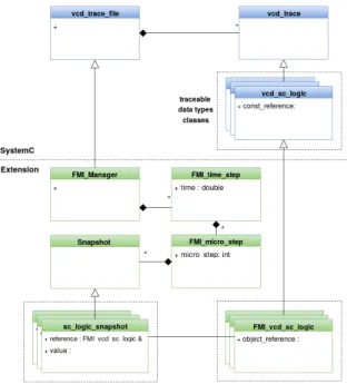
To be able to simulate a SystemC design, all its ports must be bound, otherwise, the kernel will stop during the initialization phase and won’t start the simulation. To allow the simulation, we automatically generate a new SystemC compo-nent named FMI proxy, whose ports have the same types than the ports of original design, but with the opposite direction. In our approach we want to save the history of the exposed variables during a communication step. To do so, our approach generates another SystemC component named FMI Manager, which is responsible of saving the values of all the exposed variables during one step of the simulation. In SystemC there is a trace mechanism encoded in the VCD classes, used to trace value of the design ports. This mechanism ends up with a VCD file that contains the simulation history of the traced ports. To take advantage of this mechanism, we extended all of the VCD classes from the SystemC library so that they contain an array of Snapshots, which represents the entire history of all the values of the simulation of that port. For each snapshot, our FMI Manager saves all the values of the ports as well as the time of the changes into a special classes structure. We coded the information of the time into two classes called FMI Time Step and FMI Micro Step (i.e., the trace encodes super dense time). The FMI Micro Step represents the delta cycle and it contains an index, that is the number of the delta cycle, and an array of FMI Snapshot references. An array of FMI Snapshot is needed because it is possible to have many new values in a single delta cycle. The FMI Time step represents the time step; it has a time attribute and an array of FMI Micro Step references, because for a single time step it is possible to have several delta cycles. When the simulation moves forward, the SystemC kernel calls the cycle method from the VCD classes but overridden in our trace manager to create the trace structure. This resulting class structure (see Figure 3) allows to retrieve all the value change information without data redundancy; i.e., starting from a time step it is possible to retrieve all the micro-steps and all the snapshots of that time step, and, starting from a snapshot, it is possible to retrieve the relative micro-step and time step where its value changes. This kind of structure is named “Multi-dimensional trace” [13].
The transformation also generates a main.cpp file, where these two modules are instantiated and bound together. Actu-ally, because the original main file can be quite complex (due for instance to the initialization phase), the new main.cpp is a clone of the original one with additional lines to instantiate and bind the newly generated component. In the main.cpp the transformation also creates an instance of the FMI Manager, and the instructions to trace all the ports of the design.
Another important added part is the clock generator, needed to export synchronous RTL designs. During the transformation process, it is asked the user whether the model needs a clock generator or not and, if needed, what is the master clock
Fig. 3. Class diagram our SystemC trace management for FMI.
port. The clock generator is a process of the Fmi Proxy, automatically generated and linked to the port indicated by the user. The clock generator is needed when you want to simulate the generated FMU with FMUs from other domains, for example where you have a digital part and a physical part linked together. The clock generator is not needed when you want to co-simulate two digital components as two different FMUs.
Once all these files generated, we can compile the resulting code and obtain an executable. However, it is not possible to export a SystemC module, with the SystemC kernel as a library without modifying the source code of the SystemC kernel. The problem comes from the entry point of the program (the main() function), which is hidden inside the SystemC library itself. To overcome this problem, we create two processes with inter process communication in between. This is detailed in the next Section.
The type mapping between SystemC and FMI is the same as the one defined in Section III-B. Additionally, FMI provides the signature of a set of C functions and their role in the communication between the coordinator and an FMU. We now have to implement these functions in the Fmi Proxy component to allow communication with the coordinator.
There are six main functions defined by the FMI stan-dard for co-simulation: Fmi2Set, Fmi2Get, Fmi2Instantiate, Fmi2SetupExperiment, Fmi2DoStep and Fmi2FreeInstances.
a) Fmi2Set and Fmi2Get: permit to set and get the values of the exposed variables from and to the coordinator. There are actually four kinds of set and get methods, one for each data types of the standard. For instance the set method for the Fmi2Integer exposed variables is Fmi2SetInteger, for Fmi2Real exposed variables is Fmi2SetReal and so on. For a specific data type, each exposed variable of this type is
identified uniquely by an ID called value reference. In the FMI Proxy we generated four vectors, one for each FMI type, which contains the pointer to the exposed variable. The position in the vector of each exposed variable corresponds to its value reference.
b) Fmi2Instantiate: is responsible for the instantiation of the FMU, more in details it must call the generated main.cpp file, in charge of instantiating the design, the FMI Proxy, the FMI TraceManager and corresponding bindings. The exact implementation of this function is detailled in the next Section. c) SetupExperiment: This method initializes the FMU with the initial values of the exposed variables given in the XML file. It also executes the initialization phase of the model and of the FMI Proxy. To do that, the sc start() method is used. While usually it takes an argument defining the simulation time, when given with a value of zero, it runs until the next micro step. In consequence, the first call of sc start(0) runs the elaboration phase but stops before the actual simulation.
d) Fmi2Dostep: is the core function of the co-simulation interface because it simulates the model contained in the FMU for a specific time interval. Once again, the sc start() function is used with, as parameters, the difference between the end and the start times asked by the coordinator.
e) Fmi2FreeInstances: frees all the structure and the resources used by FMU. When the coordinator calls this function the FMI Proxy calls the sc stop() SystemC function, which stops the simulation, deallocates the structure from the memory and frees the resources.
Since the IP-XACT description does not hold clock infor-mation and consequently the transforinfor-mation is parameterized by the user to know if the design needs a clock generator or not and, if needed, what is the master clock port. The clock generator is a process inside the Fmi Proxy, generated automatically and linked to the port indicated by the user. The transformation is also parameterized by the clock period of the clock generator.
D. Creation of the FMI-compliant dynamic library
In the FMU, the simulation model must be provided as a C library (i.e., .so or .dll), with the implementation of all the functions defined by the FMI standard. As explained previously, it is not possible to export a SystemC RTL design as a library due to the program entry point already defined in the SystemC kernel library. Because we did not want to modify the SystemC library, we compile the SystemC design as an executable and we launch it in a specific process. The actual interface with the coordinator is then launched in another process and inter process communication is used between them. We consequently defined a communication protocol between the two processes to exchange data and commands. It is clear that our solution suffers the inter process communication cost because we did not want to modify the SystemC library. However, future work will investigate a solution in which the SystemC library is slightly modified to avoid such cost.
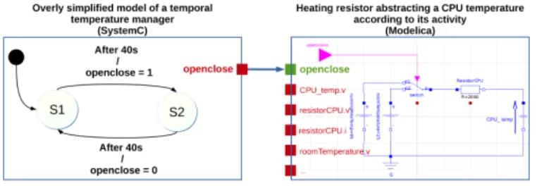
Fig. 4. A simple example mixing SystemC and Modelica
The commands defined in the protocol are: Set, Get, Sim-ulate and Finish. In the FMI Proxy there is a main routine that is responsible of mapping these commands and their parameters from and to the FMI interface functions. For instance, considering that the coordinator calls the Fmi2Set function, the pipe conveys the Set command followed by the FMI type, the value reference of that type and finally the new value to set. All the other commands and their results are communicated through the pipe in the same way.
IV. EXPERIMENTS ANDRESULTS
By using the proposed automatic generator, it is possible to export a model that describes a cyber system written in SystemC RTL into an FMU with the co-simulation interface. It is then possible to co-simulate it with other FMUs.
In this section we depict an experiment that co-simulated two FMUs connected by a coordinator written in pyFMI (http://www.jmodelica.org/page/4924), a python bridge to the official FMI library. The FMU exported from a SystemC model is co-simulated with a Modelica FMU.
The Modelica FMU is a resistor-capacitor electric circuit with two generators and a switch, named openclose (see Figure 4). The exported electrical model, named Heating Resistor FMU, describes the thermal behavior of a CPU in which the switch state represents the activity/inactivity of the CPU. This FMU has several exposed variables that can be set and get from the coordinator. In our experiments we fixed the values of the generators, the resistor and the capacitor. We used only two exposed variables: the openclose Boolean input variable representing the state of the switch, and the Cpu tempReal output variable that represents the temperature of the CPU.
In our experiment, the SystemC FMU, named Timed FSM FMU, describes an overly simplified temperature manager specified by a timed state machine with two states S1 and S2and a single Boolean output exposed variable (openclose). After 40 seconds in the state S1, the transition between S1 and S2 is fired. During this transition the openclose variable is changed from false to true. After 40 seconds in state S2, the transition from S2 to S1 is fired, changing openclose to false. After coding the state machine in SystemC, we generated the Timed FSM FMU by using the proposed tool with a clock generator process and a clock period of 1 second. In this case, because there is only a (one way) causality from the SystemC to the Modelica model, the coordinator simulates the
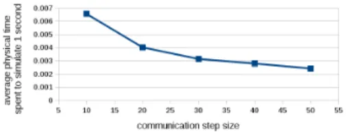
Fig. 5. CPU time spent for 1 sec. of simulated time as a function of the communication step size.
Fig. 6. Number of integration steps of the FMU solver, for 1 sec. of simulated time as a function of the communication step size.
Timed FSM FMU until the openclose changes. To do so, the coordinator calls the Simulate method with a specific start and end times (explained later) until the openclose exposed vari-able changes. When it changes it saves the current simulated time. Then, the coordinator simulates the Heating Resistor FMU for the previously saved amount of time (with the value the openclose exposed variable had on this interval). In other words, since the causality is one way, the coordinator simulates the state machine until the openclose variable changes and then it simulates the physical model for the amount of time between two changes of the openclose variable.
To understand how to make efficient co-simulation, we varied the transition time between S1 and S2. As a result, both the simulation time and the number of integration steps made by the Modelica solver decrease when the size of the communication step increases (see Figure 5). This was expected since the integration steps are (usually) optimized when the required simulation step size increases (see Figure 6 where the number of integration steps computed by the solver decreases when the communication step size increases. This is mainly due to the optimization of the integration step size according to the derivatives of the model variables when the communication step size is big enough).
V. FMI LIMITATIONS
From the various experiments driven by our automatic export of a SystemC design as an FMU, we identified some lacks of FMI, which forbids an efficient co-simulation of cyber and physical models. This section explains these lacks and sketches propositions toward a conservative enhancement of the FMI API.
A. History of values between communications points
During a co-simulation, the coordinator can retrieve the current value of the exposed data at discrete communication
points. Additionally to its current value, the derivative of continuous-time data can be retrieved (e.g., to enable inter-polation). However, when a cyber model is simulated, there are discrete-time data, which can change arbitrarily often; i.e., very often at a specific point of the simulation and almost never at some other points and possibly with an infinite derivative (consider for instance the current state of a state machine or the Boolean state of a button). Retrieving the current value of these data at the considered communication points is not efficient an can lead to a loss of information or precision.
For instance, let us consider a simple system with three FMUs. The first FMU is a cyber model which deals with a push button. Its exposed variable is the state of this button. A second FMU is again a cyber FMU in charge of interpreting the action on the button: One ”short” push on the button create a toggle command for a light in the environment, managed by a third, physical, FMU. One ”long” push on the button when the light is already on must order an increase of the light luminosity according to the time the button is kept pushed. Finally the third FMU manages the light and its effect on the physical environment. In this specific case the second FMU need to know the state of the button given by the first FMU but it also needs to know the timing associated to this state. If the communication step size is too big, then some discrete time information can be lost (see left part of Figure 7). Also, when it is required to compute the time a specific value is maintained, the size of the communication step must be chosen according to the expected precision in time (see right part of Figure 7). In both cases the communication size can be reduced enough to reduce the problems. However it comes with a significant increase of the simulation time as shown in the experiments section when increasing the number of communication points. Additionally, reducing the communication step size is not a solution to correctly handle sequences of events or value changes occurring in zero time; i.e, value changing during micros steps of the simulation (see for instance the rational of super dense time [14]). The reader should note that we are not claiming that such behavior cannot be encoded in FMI (for instance by using rejected steps and absent values [5]). What we want to stress is that, in co-simulation mode of cyber models it can be problematic to retrieve only the current value of exposed variable at discrete communication points. It can lead to an unnecessary increase of the communications between FMUs and the coordinator, leading to bad performances.
What we propose to solve this problem is the possibility to retrieve all the time-stamped values of a data, which occurred during the communication step. This would avoid reducing the communication step size while enabling the coordinator to query the history of the data in order to avoid information loss and obtain a better precision about the timing. In order to be compliant with what is existing in the FMI standard, it could be possible to use a super dense time trace of the data evolution when retrieving its values at communication points. In the same idea, it could be beneficial to enable setting not only the current value of an input exposed variable at a specific
Fig. 7. Problem when only the current value is retrieved at communication points
Fig. 8. Problem when using a periodic system with a period >> WCET
communication point but rather to provide a temporal sequence of value changes during a communication step. Once again it would reduce the required number of communication points. While this is quite obvious how to do it for cyber models, how to manage such input trace efficiently for physical models is an open problem we did not study yet.
B. Event driven communication with FMUs
The co-simulation mode of FMI is time-driven. The com-munication between an FMU and the coordinator is made at regular points in time named communication points. This is convenient for the persistent signal-based semantics of the systems originally targeted by FMI. However, when used with cyber models following the Discrete Event semantic model, it becomes cumbersome. For instance, let us consider a model of a real time system. It works periodically for a maximum amount of time denoted WCET (Worst Case Execution Time). When the period is largely bigger then the WCET (see Figure 8) the coordinator queries the FMU at regular points in time even if the system is actually not doing anything. This is mandatory since the FMU is seen as a black box and the communication step size has to be adequate to the time between successive actions when the system is working.
Nowadays, to avoid this undesired behavior, the coordinator can use variable communication step size. However, because an FMU is a black box from the coordinator point of view, the coordinator has to adapt the step size by using a try and error mechanism. To avoid this, it seems interesting to add the possibility to simulate an FMU until the next change on its exposed variable. In this hypothesis, the coordinator run the FMU without ending time (i.e., with an a priori infinite communication step size), the ending time being given by
the FMU when it pauses its simulation. Note that, if the coordinator is interested by any change in any of the exposed variables, this behavior can be encoded with the actual FMI API by asking an FMU to simulate for a ridiculously big amount of time. In this case the FMU can reject the proposed step size at the time the first changed occurred. In this case it can still advance for the processed amount of time. However, for more flexibility the proposed API could be used to specify a list of sensitive exposed variable, asking the FMU to stop only when a change occurs on these sensitive variables.
Note that this proposition could also make sense in the context of physical model for which we want to simulate until the next zero crossing of a sensitive exposed variable.
C. Native Event Type support
FMI supports only 4 data types. When considering some cyber system specification languages, the notion of event is of prime importance (see for instance synchronous programming languages like Signal or Esterel [15], or languages used to react to user actions like Javascript (http://www.w3schools. com/js/js htmldom events.asp) or Qt (https://www.qt.io/)). As stated in [5], FMI badly supports the notion of Events. It seems interesting to natively support the Event type in order to ease co-simulation of cyber models. The Event type value could then be a couple timestamp and eventually a data type value.
VI. RELATEDWORK
We know three other approaches that export a Sys-temC design as an FMU: [7], [16], [9]. However there exist fundamental differences between these approaches and the one proposed in this paper. In [7], the authors pro-posed an approach to export a SystemC virtual platform as an FMU. Their approach strongly depends on the Plat-form Architect tool (http://www.synopsys.com/Prototyping/ ArchitectureDesign/Pages/platform-architect.aspx) and conse-quently the paper only presents an high level architecture of the proposed solution. Many components of their architecture were already covered by Platform Architect (e.g., the extrac-tion of the exposed variables or the required interface to get and set them). The approach is consequently available only in platform architect. More importantly they do not give any detail on the flavor the SystemC design must conform (RTL only ?, TLM ?, timed ?). This makes difficult to understand if they solved the various issues that can arise, for instance when using untimed designs. In the opposite, in this paper we made clear that only RTL synchronous SystemC designs are supported for now. We also detailed all the steps needed to create an FMU based on the open source SystemC library. Finally, we proposed extensions to the FMI standard for a more efficient support of cyber models in co-simulation. In [9], the authors proposed to use a networking extension of SystemC to develop networked cyber physical systems. No details are given on how SystemC is exported as an FMU. They state that their approach requires that all the cyber models and the network have the same speed, both internally and in terms of communication step size. According to us, this is
due to the first FMI limitation we pointed in section V and consequently acknowledge the need for FMI enhancements [8] proposed to export a SystemC/SystemC-AMS design as an FMU. This approach diverges from our approach because they use continuous designs written in SystemC-AMS. Con-sequently they did not study the use of cyber models in the FMI environment. Additionally, unlike us the FMU creation process is not automated but written manually.
Apart from SystemC, there is recently an increasing interest in studying the use of FMI for cyber physical systems. Only few of these approaches study the limitations induced by the use of cyber models in an FMI environment [4], [5], [6], [10]. [10] is dealing with the import of a Modelica model into the Ptolemy environment [17]. They co-simulated a discrete event model with a physical model. However in one hand they use FMI for model exchange and not for co-simulation and in the other hand they did not export a discrete event model as an FMU but instead they import the FMU of a physical model into their environment; the problems are consequently different than the one addressed in this paper. orer[4], [5], [6] are a set of correlated papers on 1) the formalization of FMI [4], 2) the study of how to bridge the semantic gap between FMI and various other models among which cyber models [5] and 3) a Ptolemy based environment for heterogeneous co-simulation based on the FMI standard [6]. These interesting papers explain theoretically how some cyber models can be encoded in a way they can be used in an FMI environment. It states some lack on the management of discrete events and propose to add the absent value to FMI in order to deal with discrete event that are not continuous-stated as expected by FMI. While we share the different observations they did, we tried to understand in this paper how to provide a native management of cyber models in FMI, without mangling existing models for this specific purpose. Additionally, we proposed in this paper a new SystemC-RTL FMU exporter.
VII. CONCLUSION& FUTURE WORK
In this paper we studied how FMI manages the use of cyber models in co-simulation mode. This study provides two contributions. The first contribution is an automatic FMU ex-porter for legacy SystemC RTL designs. An exported SystemC design was co-simulated with a modelica model to ensure the conformance of our FMU with the standard. The second contribution came from the study of the various experiments we did. It is an analysis of some lacks of the FMI standard when co-simulating cyber models with non persistent signal based semantics (in our case SystemC follows a discrete event semantics). We also proposed some solutions to enhance FMI when used in this context.
Many future works can be considered after this study. The first one consider the exporter. We rely now on ScipX, which is an academic tool only suitable to SystemC. We plan to consider other cyber languages like VHDL or Verilog. In this context it can be interesting to use more mature tools like HIFSuite (http://www.hifsuite.com/) to extract the design inter-face. It is also planned to slightly modify the SystemC library
to avoid the cost associated to inter process communications. We also want to implement the new FMI features proposed in this paper. Then, we want to study what information may be exhibited by an FMU in order to automatically reason on causalities in the whole system. Reasoning on such causalities can ultimately lead to the automatic generation of optimized coordinator.
REFERENCES
[1] B. Combemale, J. Deantoni, B. Baudry, R. B. France, J.-M. J´ez´equel, and J. Gray, “Globalizing Modeling Languages,” IEEE Computer, pp. 10–13, Jun. 2014. [Online]. Available: https://hal.inria.fr/hal-00994551 [2] Modelisar, “FMI for Model Exchange and Co-Simulation,” July 2014.
[Online]. Available: {https://fmi-standard.org/downloads#version2} [3] F. Fummi, D. Quaglia, and F. Stefanni, “A systemc-based framework
for modeling and simulation of networked embedded systems,” in Specification, Verification and Design Languages, 2008. FDL 2008. Forum on. IEEE, 2008, pp. 49–54.
[4] D. Broman, C. Brooks, L. Greenberg, E. A. Lee, M. Masin, S. Tripakis, and M. Wetter, “Determinate composition of fmus for co-simulation,” in Proceedings of the Eleventh ACM International Conference on Embedded Software, ser. EMSOFT ’13. Piscataway, NJ, USA: IEEE Press, 2013, pp. 2:1–2:12. [Online]. Available: http://dl.acm.org/citation.cfm?id=2555754.2555756
[5] S. Tripakis, “Bridging the semantic gap between heterogeneous model-ing formalisms and fmi,” in Embedded Computer Systems: Architectures, Modeling, and Simulation (SAMOS), 2015 International Conference on, July 2015, pp. 60–69.
[6] F. Cremona, M. Lohstroh, S. Tripakis, C. Brooks, and E. A. Lee, “Fide– an fmi integrated development environment,” 2016.
[7] R. L. Bucs, L. G. Murillo, E. Korotcenko, G. Dugge, R. Leupers, G. Ascheid, A. Ropers, M. Wedler, and A. Hoffmann, “Virtual hardware-in-the-loop co-simulation for multi-domain automotive systems via the functional mock-up interface,” in Specification and Design Languages (FDL), 2015 Forum on. IEEE, 2015, pp. 1–8.
[8] M. Krammer, H. Martin, Z. Radmilovic, S. Erker, and M. Karner, “Standard compliant co-simulation models for verification of automotive embedded systems,” in Specification and Design Languages (FDL), 2015 Forum on. IEEE, 2015, pp. 1–8.
[9] N. Pedersen, J. Madsen, and M. Vejlgaard-Laursen, “Co-simulation of distributed engine control system and network model using fmi & scnsl,” IFAC-PapersOnLine, vol. 48, no. 16, pp. 261–266, 2015.
[10] W. M¨uller and E. Widl, “Linking fmi-based components with discrete event systems,” in Systems Conference (SysCon), 2013 IEEE Interna-tional, April 2013, pp. 676–680.
[11] IEEE, “IEEE 1685: IP-XACT, STANDARD STRUCTURE FOR PACKAGING, INTEGRATING, AND REUSING IP WITHIN TOOL FLOWS,” 2014. [Online]. Available: {http://standards.ieee.org/getieee/ 1685/download/1685-2014.pdf}
[12] J. F. L. Tallec and R. de Simone, “Scipx: A systemc to ip-xact extraction tool,” in Electronic System Level Synthesis Conference (ESLsyn), 2011, June 2011, pp. 1–6.
[13] E. Bousse, B. Combemale, and B. Baudry, “Towards scalable multidi-mensional execution traces for xdsmls,” in 11th Workshop on Model Design, Verification and Validation Integrating Verification and Valida-tion in MDE (MoDeVVa 2014), 2014.
[14] E. A. Lee and A. Sangiovanni-Vincentelli, “A framework for comparing models of computation,” Computer-Aided Design of Integrated Circuits and Systems, IEEE Transactions on, vol. 17, no. 12, pp. 1217–1229, 1998.
[15] A. Benveniste, P. Caspi, S. A. Edwards, N. Halbwachs, P. Le Guer-nic, and R. De Simone, “The synchronous languages 12 years later,” Proceedings of the IEEE, vol. 91, no. 1, pp. 64–83, 2003.
[16] A. Vachoux, C. Grimm, and K. Einwich, “Systemc-ams requirements, design objectives and rationale,” in Proceedings of the conference on Design, Automation and Test in Europe-Volume 1. IEEE Computer Society, 2003, p. 10388.
[17] B. Evans, A. Kamas, and E. A. Lee, “Design and simulation of heterogeneous systems using ptolemy,” in Proceedings of ARPA RASSP Conference, 1994.