Design, Modeling, and Validation of an Apical
Flow Transwell Insert for Small Intestinal Models
by
Transon Van Nguyen
Biomedical Engineering, University of California, Irvine (2010) Biomedical Engineering, University of California, Irvine (2012) Submitted to the Department of Mechanical Engineering in partial fulfillment of the requirements for the degree of
Master of Science in Mechanical Engineering at the
MASSACHUSETTS INSTITUTE OF TECHNOLOGY September 2015
@2015
Transon Van Nguyen, All rights reserved.The author hereby grants to MIT and The Charles Stark Draper Laboratory, Inc. permission to reproduce and to distribute publicly paper and electronic copies of this
thesis document in whole or in any part medium now known or hereafter created.
Author ...
Ceri-fie b1
Signature redacted
De ment of Mechanical Engineering
June 26, 2015
Sianature redacted
y ... .... . . . .... . . . ....
Linda G. Griffith School of Engineering Professor o I vation Biological, and Mechanical
Engineering Thess Supervisor Certified by ...
Signature redacted
David L. Trumper Professor of Mechanical Engineering Thesis Reader
Accepted by
...
Signature redacted
bavifE. Hardt
Ralph E. and Eloise F. Cross Professor of Mechanical Engineering Graduate Officer, Mechanical Engineering
MASSAW4USEYMMS11TUTE -OF EC H W O L O G Y
OCTOCT
1 201
LIBRAR
IES
Design, Modeling, and Validation of an Apical Flow
Transwell Insert for Small Intestinal Models
by
Transon Van Nguyen
Submitted to the Department of Mechanical Engineering on June 26, 2015, in partial fulfillment of the
requirements for the degree of
Master of Science in Mechanical Engineering
Abstract
This thesis presents the design, modeling and experimental validation of a device that allows for apical flow over an in 'vitro small intestine model. The device is designed to interface with commercially available hanging Transwells. Design considerations and specifications are discussed, based on user considerations, mechanical requirements, and biological requirements. To create a more informed design, multiple phenomena are modeled and results are used to modify design characteristics and give insight into viable operating parameters, such as apical flow rate. Within the device, veloc-ity profiles of media flow as well as oxygen transport and cellular oxygen consumption are modeled. External to the device, heat transfer from a warm incubator into room temperature tubing containing media is modeled to ensure proper media warming. Experimental validation of the flow models is done by tracking dye flow through the insert, and preliminary flow experiments appear to be in agreement with modeling re-sults. The design, modeling, and experimental results discussed in this thesis present a promising step toward a device capable of maintaining oxygen gradients that re-capitulate specific aspects of the complex, dynamic environment within the small intestine.
Thesis Supervisor: Linda G. Griffith
Title: School of Engineering Professor of Teaching Innovation, Biological, and Me-chanical Engineering
Acknowledgments
I would first like to thank my advisor, Linda Griffith, for her guidance. I have grown significantly since I entered MIT, and Linda is to thank for this-she has played a large part in instilling a stronger sense of rigor into everything that I do.
I would also like to thank my thesis reader, Dave Trumper, for his feedback on this thesis as well as his many design insights during our meetings, many of which have shaped the design of this device.
The numerous helpful discussions with Rebecca Carrier, Collin Edington, Emily Suter, Julia Kudryashev, and Kelly Chen have no doubt influenced the design of this insert. Special thanks to Emily, Julia, and Collin for taking the lead on running biology experiments and designing the next iteration of this device.
I am thankful to the Charles Stark Draper Laboratory for supporting me as a Draper Lab Fellow during my time at MIT.
Contents
1 Introduction
1.1 The Gut Microenvironment ... 1.2 Previous Work . . . .
1.2.1 Static In Vitro Small Intestine 1.2.2 Devices with Flow . . . . 1.2.3 Our In Vitro Model . . . . 2 Designing the Apical Insert
2.1 Concept . . . . 2.2 The Transwell . . . . 2.3 The Apical Flow Insert...
2.3.1 Components and Geometry 2.3.2 Operation . . . . 2.4 Apical Flow Insert Requirements
2.4.1 Mechanical Considerations 2.4.2 Biological Considerations . 2.4.3 Design Parameter Reduction
3 Computational Models of Fluid Dynamics, Reaction, and Heat Transfer
3.1 Model Geometry . . . . 3.2 Flow Modeling . . . . 3.2.1 Setup . . . . 3.2.2 Inlet and Boundary Conditions . . . 3.2.3 Results
3.3 Oxygen Transport and Reaction with Mammalian 3.3.1 Setup . . . . 3.3.2 R esults . . . . Culture Models 8 9 11 12 13 15 17 18 19 21 21 24 26 27 29 31 Oxygen Transport and
35 36 38 38 40 42 45 46 51 . . . .
3.4 Heat 3.4.1 3.4.2 3.4.3 Transfer in an Incubator . . . . Setup . . . . Analytical Solution . . . . Finite Element Model Results 4 Preliminary Experimental Validation 4.1 Priming . . . . 4.2 Flow . . . . 5 Discussion and Conclusions.
5.1 Future Work . . . . 5.1.1 Lid Design . . . . 5.1.2 Contact and Sealing Improvements 5.1.3 Apical Flow Dimensions . . . . 5.1.4 Sensor Integration . . . . 5.2 Conclusions . . . . A.1 A.2 A.3 Bill of M aterials . . . . Technical Drawing: Apical Insert . . . . . Technical Drawing: Lower Ring . . . . A 55 56 57 61 64 65 66 69 69 69 71 72 73 74 76 76 77 78 79 References . . . . . . . .
List of Figures
1-1 Diagram of oral drug pathway . . . . 1-2 Illustration of intestinal wall structure . . . . 1-3 Solid models of shear device . . . . 1-4 Illustration of "gut-on-a-chip" device . . . . 1-5 Illustration of current Griffith Lab small intestine model 2-1 2-2 2-3 2-4 2-5 2-6 2-7 2-8 2-9
Schematic of dynamic in vitro gut microenvironment Illustration of Transwell hanging in a well . . . . Illustration of Transwell locating feature . . . . Exploded and assembled view of apical flow insert . . Cross-section view of apical flow insert . . . . Schematic of system setup for apical flow . . . . Flat-bottom port dimensions . . . . Rotational constraints during assembly . . . . Technical drawing of apical insert . . . . 3-1 3-2 3-3 3-4 3-5 3-6 3-7 3-8 3-9 3-10 Model geometry . . . . Schematic of conditions for flow modeling . . . . Illustrations of apical flow geometries . . . . Flow model results for bore inlets . . . . Flow model results for slot inlets . . . . Schematic of conditions for oxygen modeling Oxygen transport/consumption model results Schematic of system setup for media warming in Plot of analytical solution of heat transfer . . . FEA heat transfer results . . . .
an incubator
4-1 Time series of priming assembled apical insert .
4-2 Time series of dye flow in apical chamber . . . .
5-1 Rendering of custom plate lid . . . . 5-2 Contact and sealing improvements . . . .
9 10 13 14 15 . . . . 18 . . . . 19 . . . . 20 . . . . 22 . . . . 23 . . . . 26 . . . . 27 . . . . 28 . . . . 34 37 41 42 43 44 47 53 57 63 63 66 67 71 72
List of Tables
2.1 Design and Operation Parameters . . . . 33
3.1 Parameters for Modeling Media Flow . . . . 42
3.2 Comparison of Oxygen Consumption Values . . . . 49
3.3 Parameters for Flow and Oxygen Transport . . . . 51
Chapter 1
Introduction
The small intestine is a remarkably complex organ. Functionally, it plays a crucial role in nutrient absorption: food that is mostly digested by the stomach is passed to the small intestine, where essential nutrients (e.g. sugars, amino acids, fatty acids) are transported out of the intestine and into the bloodstream. This process, however, does not only apply to food; the small intestine also plays a large role in drug absorption, as drug metabolism in the intestinal epithelial layer (followed by further metabolism in the liver, in many cases) significantly affects the bioavailability of orally administered drugs, as illustrated in Figure 1-1 [1, 2].
For this reason, among others, there is a growing body of work focused on fur-ther understanding the small intestine's barrier and drug metabolism roles. In this chapter, we will discuss approaches to creating in vitro models of the small intestine, which are particularly useful for testing during early stage drug discovery in the drug development process.
ORAL DRUG INTAKE Drug Disintegration and Dissolution
Loss via Luminal Degradation Diffusion through Gastrointestinal Fluids
Membrane Permeation
Loss via Mucosal Metabolism Uptake into Blood or Lymph
Loss via Hepatic Metabolism Drug in Systemic Circulation
Bound Tissue Drug Concentrations Bound Drug 4 * Unbound Drug
Clearance 4 1
Free Tissue Drug Concentrations Active Site Concentrations
EFFECT
Figure 1-1: Diagram of the relationship between an orally administered drug and its ultimate effect. Note the multiple paths for drug loss, particularly through mucosal metabolism of the small intestine
followed by further metabolism in the liver. From [2]. Reprinted with permission by John Wiley & Sons, Inc.
1.1
The Gut Microenvironment
We begin with a brief description of the anatomy and microenvironment of the small intestine. As previously stated, partially digested food (called "chyme") enters the small intestine from the stomach. This chyme slowly passes through the lumen of the small intestine, pushed forward through peristalsis-a wave of muscle contractions that travel down the length of the intestine. Intestinal epithelial cells known as enterocytes line the inner wall and form finger-like protruding microstructures called villi, as illustrated in Figure 1-2. It is widely accepted that the purpose of this villus structure is to increase the available surface area for absorption.
o.1-1 anaerobic microbes
.4 - facultative microbes - . shed epithelial cell
10-20 mucus
macrophage. intraepithelial
lymphocytes, dendritic & plasma cells
20-40-epithelial & goblet cells
terminal blood &
02 lymph vessels
crypt progenitor, endocrine &
(mm Hg) ,Paneth cells submucosa
80-100
Figure 1-2: Overview of intestinal villi anatoniv, with oxygen concentrat ion in relation to radial
position drown on the left. Note the Steep gradient from the oxvgelated subimcosa to the nearly
anoxic limen. Reprinted from [3], @2013. with perinission from Elsevier.
houses several tvpes of iimniie cells. The iimine componlent strongly colntr1i) butes to the harrier function of the small intestine. as it must prevent pathogenic
ulieroor-ganisls from crossing tie epithelium and entering the bloodstream. However. not all microbes are pathogenic there exists a host of commensal nicrobes within the luen that assist with further ldigestiomn of ClIme.
The oxygen tension distribution in the gut is worth noting here. For the most part. tissue near the intestinal wall is oxygenated as a result of the proxillmity to blood vessels withini the laimiina propria and subimucosa. As oxygen diffhses through the epitlielium and iito the Iimmen. it is consumimied by inmnnunle clls. enterocvtes. mnicrobes near the epithelillimn. and amy other aerobic constituents in the diffusion path. As a result of this dense concentration of oxygen-consmumming species. oxygen tension quickly decreases as one moves fron the submmucosal layer to the limien. to the point where the environment is nearly anoxic 1 hun awvav from the epitliheluim. As annotated in Figure 1-2. this
creates a complex distribution of microbes: iicroacrophiles and facultative anaerolbes will cluster near the oxygenated epitheliumn, while obligate anaerobes remain iin the
hypoxic and anoxic areas deeper within the lumen. Thus, the steep, decreasing oxygen gradient in the gut results in a population density gradient of microbes-similarly decreasing for facultative anaerobes, and increasing for obligate anaerobes [3].
1.2
Previous Work
When attempting to translate the complex, dynamic environment of the small intes-tine into an in vitro model, the prime question to ask is which in vivo characteristics should be recapitulated in vitro. For example, if one wishes to study drug absorp-tion, an epithelial culture is essential. However, there are deeper choices to consider: a monolayer of enterocytes may be simpler to culture (and, in turn, simpler to scale for a high-throughput test), but it would be more physiological to recreate the high surface area villi structure seen in vivo. To recapitulate barrier function, a number of additions can be made, including goblet cells to produce mucus and immune cells underneath the epithelium. The addition of commensal microbe strains to create a microbe/mammalian cell coculture may also drive the culture toward a more phys-iological state. We have yet to mention mechanical stimuli, such as shear on the intestinal wall from lumenal flow, buckling/compression of the epithelial layer dur-ing peristaltic contraction, and the proper transport conditions to create a realistic oxygen gradient.
Clearly, there are a myriad of potential approaches to creating an in vitro small intestine model, and the end approach depends on the phenomena to be studied, as well as consideration for balancing system complexity with ease of use and scalability. In this section, we give an overview of selected work in this field, including static cultures, dynamic devices that produce mechanical stimuli, and the current model under development in our lab.
1.2.1
Static In Vitro Small Intestine Models
Caco-2, a human colon carcinoma cell line, is commonly used as a model for drug absorption in the small intestine. Although the Caco-2 cell line is not derived from enterocytes, the cells are still commonly used as a model for enterocytes due to their similar morphology and function [4, 5]. In fact, the highly cited, seminal paper published in 1989 on using the Caco-2 cell line as a small intestine barrier model has been credited with catalyzing the eventual migration from in vivo and ex vivo pharmaceutical studies to in vitro studies on cell lines for drug discovery [6].
Since then, many studies have improved on the Caco-2 monolayer to create in
vitro models that more closely approximate the in vivo intestinal barrier. An
in-creasingly common approach is the addition of a gel such as collagen or Matrigel on the apical side of a Transwell membrane to facilitate the growth of 3D cultures. For example, Caco-2 cells in coculture with mucus-producing cells and stromal cells (e.g. fibroblasts) are seeded on and/or in the gel before it cures, creating a 3D culture. One such demonstration of this was published by Li et al., resulting in a structure where fibroblasts were distributed among a collagen matrix while Caco-2 and mucus-producing cells were concentrated on the apical surface of the matrix, not unlike the epithelium and its underlying lamina propria [7].
Although Caco-2 is a reliable, widely used cell line, there have also been efforts to use primary enterocytes in their place, as their function would ideally be more physiological than Caco-2 cells. However, primary cells tend to be much harder to maintain than established cell lines; although short-term (on the order of two weeks) primary enterocyte cultures have been demonstrated, culture techniques for long-term maintenance of primary enterocyte cultures are still in development to the present day [8]. A fairly recent publication by DiMarco et al. describes a system composed of organoids assembled from murine small intestine explants and myofibroblasts, seeded
on a (collagen gel that was set on a Transwell iiieibiane or at the bottoml of a well
[9]. ()rganoids assemiibled in the gel on the Transwell demlonstrated iioire contractile
behavior, potentially as a result of the illcreased oxygen tranlsport available in a suspen(led Tiaiiswell.
1.2.2
Devices with Flow
The examples described in Section 1.2.1 all utilize some form of an epithelial eiltuire on a Transwell suspiended in a umiltiwell plate. suich as a 12-well plate. Although the
oellture aid surrounding matrix may be complex. the media enviromnent in these situationis is fairly siiple as it is statie over the urse of the culture lifetime (apart froi haimdliiig oplerat ions such as mniedia replacemnent).
Air flow
Cultured cells
Plug
Medium
Side wall Main body
Base Well bottom
0-Ring
Figure 1-3: Assembled (top) and exploded (bottom) solid models of device for exposing epit'helial cultures to wall shear stress. Reproduced firom [10] with permnissio fIron Springer.
Atteniptinig a variety of cocultures under a myriatd of matrix couditiots is not the olv xav to coax cells inito a mimore physiologieal state. For exanmlple. stilnlatig the
Porous G ut \membrane, epitheliumn 7--Vacuum \acuum chamber chamber
d
Mechanical strainFigure 1-4: Illustration of *gut-oi-a-chip device. Gut epitielial cells are Seeded on a porous
nem-branle Suispended iII the center of a microfllidic chamiber. Inlets to the device allow for media flow on
both the apical aid basal sides of the culture. Emlptv chambers on the sides can be evacuated of air
to create a vacImiI. which stretches the membrane aid induces strain on the culture. Reproduced
from [11] with perimission from The Boyal Societv of Chemistry.
realistie hehavior. particllarly among (eli types that typically reeeive such stimuli 'in
'0 wh iuding enterocytes. To this effet,. there have been inany Hi liquie approaehes
for introdieing shear to in vitro eultures. One such approach is illustrated in Figure
1-3. where a (listoim devie has been designed to house several cultures arranged eollinearly [10]. Wk hen the device is assenbled. the apical seetions of the cultures
are sealed off from the suirroulnding atniosphere. and the only aeeess is through an
inlet anid outlet ehannel on the apical side. When air flows through the ehannel (and technically media (0o1ld work here as well). the eell ciiltuires at the bouindary of the (hanilel experiele a wall shear stress that ('o0ul( be nodeled or (alcillated fairly easily. and the auint of shear can be eontrolled sinply by varying flow rate.
by Kim et al., which is illustrated in Figure 1-4. The device utilizes a microfluidic
approach to an in vitro intestinal model; the cell culture is seeded on a membrane suspended in a microfluidic chamber, and media flow on both sides of the culture is made possible by flowing through inlet connections to the chamber. In contrast to the shear-inducing device in Figure 1-3, this device can be thought of as fully-enclosed and fully-integrated. There are no sub-components to assemble and disassemble; the device is, for all intents and purposes, a single part. This approach has its share of benefits and drawbacks. For example, while it is simpler for a user to physically handle the device, it is also harder to initially operate during an experiment, as cell seeding is not as straightforward as seeding on an open insert which can be done with the shear-inducing device.
1.2.3
Our In Vitro Model
IV dosing Transwell
oral dosing
enterocyte goblet cell
macrophage
basal effluent basal feed
Figure 1-5: Illustration of in vitro small intestine model currently under development in our lab.
Basal flow is accomplished by a multi-tissue culture platform, also developed in-house. This culture model will form the basis for the device presented in this thesis.
The in vitro small intestine model currently under development in the Griffith lab [12], in collaboration with Rebecca Carrier at Northwestern University and Doug
Lauffenburger at MIT, is illustrated in Figure 1-5. Briefly, a coculture of enterocytes and mucus-producing goblet-like cells are grown on the apical side of the membrane of a Transwell while macrophages are seeded on the basal side. Thus, the apical media is analogous to the lumenal environment, while the basal media is analogous to systemic circulation. The Transwell can be placed in a well within a multi-tissue culture platform, developed in-house, that allows for basal media flow. This flow comes in the form of recirculation, media transfer from one well to another on the platform, or both.
We note here that this approach, in contrast to the examples given in Section 1.2.2, is a particularly beneficial mix of custom-developed solutions and commercial-off-the-shelf components; by using the nearly ubiquitous Transwell, the barrier to adoption of such a system is reduced, as many research groups already use Transwells to develop their own in vitro models.
However, there is currently no apical flow within our model, as the platform is currently designed only for basal flow within and between cultures. If the capability for apical flow on our model could be achieved, a more physiological apical microen-viroinent could be created, which in turn may drive our culture toward more in
Chapter 2
Designing the Apical Insert
As a step toward improved control of the apical microenvironment within our in
vitro small intestine model, we present an apical insert that fits over a commercially
available Transwell and allows for increased functionality. Namely, the insert allows for continuous apical media replenishment and control over local oxygen tension, capabilities that are not typically available in a standard Transwell in a static well.
This chapter describes various aspects of the design process behind the apical flow insert. We begin by illustrating the ideal concept behind the apical insert, followed by an examination of the commercially available Transwell and how particular fea-tures can be used advantageously for compatibility with the apical insert. The apical flow insert itself is then presented, with general notes on overall design and opera-tion. To better elucidate the design process behind the insert, we then delve into a detailed discussion of design and operational specifications, both from a mechanical and biological perspective.
apical effluent apical feed
transwell
mucin
goblet cells
apical flow insert
apical seal
microbes
enterocytes
basal effluent
macrophages
basal feedFigure 2-1: Schematic view of iM cidro small intestine model. The apical insert, presented in this
thesis, provides imedia flow oi1 the apical side of the m1embrane as well as capability for controlled
oxygen gradients within the culture.
2.1
Concept
Figure 2-1 illustrates a theoretical in vitro gut microenvironient. 1)ase(d on the
ctir-rent gut model described in Section 1.2.3. A co-culture of enteroeytes and
1m1c1(s-producing goblet-like ('(1ls are cultured on the apical side of a hanging Transwell.
Macropllages which serve as a 11od(l for illlllllllle 1s1)ons0 are seeded oii the basal
side of the Transwell mlemlbrale. A group of inicrobe strains that are minimally
relpreselltative of aii in vivo iiiciirobioiiie are introduced oil the apical si(le.
Also seen in the schematic is the piesenee of media flow on both apical and basal sides. As previously described. basal flow is accomplished through a lnlllti-tissle
vulture platfori developed independently of the apieal flow insert, and will not
1b(e
apical insert presented here. Apical flow in this I issue model serves not only as a
neaiis foi media replenisineit. but also for miiiroe Polplation control as well as imicin shearing to maintaili a relatively coistailt 1mci c oncenltration. Additionally, if the insert seals the apical side of the Trainswell from the sllrroundillg environment. this wouild allow for redcie oxygeii tension in miledia as the (ell/nmirobe culture consunies oxygen faster than it (all diffise into media thromgh the basal side. Depending on the balance of oxygen consllmption ad diffision. a iucroenviroimnent that more elosely recapit iilates the Iypoxie domain vithiii the 1umen of the small intestine may he aehievedl. 61
2.2
The T ranswell
a
flange ~ locating featureI ;~
1;
)
~jk
p -~ ~ubb~L
-Figmre 2-2: (a) Rendering of t2-well Transwell above a 12-well 11mltiwell plat ('. The Transwell flange
1(d well aninliis forim a contact pair when the Transwell is inserted into the plate. The locating
featOure assists with alignment during insertion. (h) Cutaway view of inserted Transwell.
The hanging Transwell used iii the expeiiments descrilbed here is a 12-well
Trani-swell with 0.4 pill pores in a polyethyleie terephitialate (PET) membrane (#3460. Coriing Life Seienees, Tewksbur y, \IA). Figure 2-2(a) shows a rendering of a
Trani-swell hovering above a 12-well plate, while Figure 2-2(b) illustrates a ,ross sectioial view of the Traswell iiiserted into a well. As seeii in the figure. the flange at the top
AV
A0,
'A
of the Transwell is the contact surface that allows it to hang over a well specifically, the bottom of the flange contacts the top of an an extruded annulus above the well.
and this contact pair is the only source of contact between the Transwell and
miul-tiwell plate. The solid model for the Transwell was created by measuring critical components of a phvsical Transwell with calipers multiple times. Each dimension that was inpult into the solid model was the iiean of all measurements recorded for that particular dimension. The solid model for the 12-well plate was created from diiensions provided l Corning Life Sciences [13].
Within the Transwell. there are several characteristics of note. As these compo-nents are injeetion iolded. the ilner wall of the Transwell has a slight draft angle to assist witli removal of the polystyrene shell from the mold. This draft angle must be
accounted for to ensure the apical insert fits properly when placed into the Transwell. Another interesting design feature is the presence of three discrete flange supports (as opposed to. for example. a single tapered cylindrical shell) that connect the -well" of the Transwell to the flange. The supports are rotationally symmetric of order 3
(i.e. by 1200) about the centerline of the Transwell. One added benefit of these dis-crete supports is that they can be easily grabbed with tweezers during handling, thus serving as a stable point of contact for tweezers.
OFF CENTER LOCATING CENTERED
initial contact
locating
feature
Figure 2-3: 111ustratiom of Trianswell locating feature. in additio1 to preveithig an off-ceniter
As Transwells are typically used in a sterile environment due to the presence of live cell cultures, they are almost never handled directly-as previously mentioned, tweezers are commonly used for handling. Though this method may assist with precision, one disadvantage is that it lacks an element of tactile feedback that is normally present in manual handling. To facilitate tasks such as placing a Transwell into a multiwell plate, the Transwell has features that assist with locating-the outer face of the three flange supports have an angled boss that leads to the flange itself, as seen in Figures 2-2(a) and 2-3. The purpose of this angled feature is to assist with locating the Transwell toward the center of the well, as it is unlikely that users will be able to place a Transwell precisely in the center on their first attempt. As illustrated in Figure 2-3, an off-center placement is corrected as the angled boss guides the user toward the well center.
2.3
The Apical Flow Insert
With a better understanding of the design features of the commercial Transwell, we now present the features of the novel apical flow insert developed in this thesis work. We begin with an overview of the components used to achieve apical flow within a Transwell, along with instructions for device assembly and operation during an experiment.
2.3.1
Components and Geometry
Figure 2-4 shows exploded and assembled views of the components used to create flow along the apical side of a Transwell. As labeled in the figure, the component directly above the Transwell is the apical flow insert itself. When inserted into the Transwell, the cylindrical boss on the bottom of the apical insert protrudes into the Transwell, coming to a stop before colliding with the Transwell membrane. An o-ring
compression fitting for 1/16" OD tubing 0-80 screws apical insert o-ring 12-well Transwell lower ring
Fig-1re 2-4: Expl)ded (1and assemibled view of apical flow insert with Transwell an( lower ring. The
insert is fastened to the lower rig sandwichig the Transwell to assist with reliable insertion deptih and sealing.
groove lachined into the apical insert holds two 1mlii ID x liiiiii CS Viton o-rings
(9263K549 . McMaster-Carr. Robbinsville. NJ). whiih create a radial seal between the insert and the inner wall of the Transwell. The apical insert has two internal channels which form an inlet and outlet path for media flow: details of the flow profile will
le described further in Section 3.2. Below the Transwell is the lower ring, a simple annulus with four 0-80 tapped holes that align with four clearance holes in the apical
insert.
During assembly. the apical insert and lower ring fasten together. sandwiching the Transwell between them in the process. This ensures that the apical insert is fully cx-tended into the Transwell. and also prevents the insert fron beconing loose. Finally. two compression fittings with flat-bottom ferrules (P-844X, Upehurch Scientific, Oak Harbor, WGA) can he screwed into ports on the top surface of the apical insert. thus
allowing more rigid tubing (such as PTFE or PEEK tubing) to interface with the
outlet inlet Transwell/ring contact surface 0.020 1.000 Tra n swell/insert contact surface o-ring seal
0.079
[2 mm]Figure 2-5: Cross-section \vieiw of apical flow sVsteiii. illustrating the fluid flow path and contact
surfaces between the apical insert. Traiiswell, and lower ring. A selection of critical diinensionis are labeled: the total height of the systen is 1" (neglecting fittings and tubiiing), the height of the apical flow channel created by the insert is 2 nn, and there is a 0.020" vertical gap between the Transwell in and apical insert to prevent overdeternined contact between the coniponents. Dinensions are in inches unless otherwise specified.
Figure 2-5 shows a cross-section view of the assembled system. The media flow
path through the nile fitting. insert. apical channel. and outlet fitting is highlighted. To create flow, tubing coupled to the inlet fitting caii be connected to a syringe )ump111).
although other methods for in(dicing gradial flow (e.g. gravity driven flow) may also
he viable. The height of the apical channel. a critical dimension which vill be further
discussed in Section 2.4.2. is defined to be 2 nun. Other critical features labeled
in Figure 2-5 include the o-ring seal and the contact surfaces between the insert.,
Transwcll. and ring. The 0.020" gap between the top of the Transwell and the apical insert ensures that the system is not overdetermined by an abundance of contact surfaces the Transwell/insert contact snrface adjacent to the o-rings is sufficient to
determine the vertical position of the insert relative to the Transwell.
2.3.2
Operation
Because these components must be assembled in a sterile environment, it is necessary to develop an assembly procedure that minimizes the risk of contamination during this phase. Broad guidelines for working in a sterile environment such as a biosafety cabinet include the following:
1. Keep sterile parts sterile; sterile surfaces should only be in contact with other sterile surfaces. For example, the underside of a plate lid is considered sterile, but the top is not. If the tips of sterile tweezers rest on the top of a lid, the tweezers are now non-sterile.
2. When working with sterile substances (e.g. media) or cultures, minimize expo-sure time (such as when the cap is removed from a bottle, or the lid is removed from a plate).
3. Do not pass anything non-sterile (e.g. your hand or arm) over any sterile sub-stance or culture that is exposed.
4. Minimize amount of time handling parts in general.
Additional guidelines may exist depending on the situation or laboratory; standard operating procedure varies from place to place.
With these guidelines in mind, a sterile assembly procedure can be constructed. The following procedure assumes all components are already sterilized (either by autoclaving or EtO sterilization):
1. Place the lower ring on a 12-well plate, concentric to one of the wells. The ring should sit on top of the well annulus.
2. Place a 12-well Transwell with a live culture onto the lower ring. The Transwell flange should be hanging on the lower ring, and the Transwell itself should be suspended in the well.
3. If there is apical media in the Transwell, aspirate it.
4. Gently place the apical insert (with an o-ring in the groove) into the Transwell. There is no need to press the insert down; the screws will create that force when fastened.
5. Place an 0-80 screw into each of the four clearance holes in the apical insert and fasten them to the lower ring (using a screwdriver that has either been autoclaved or sprayed with 70% ethanol).
6. Thread a pair of PEEK compression fittings and ferrules with sterile tubing, one for the inlet and one for the outlet (this step can also be completed in advance). If using a syringe pump, the inlet tubing should be connected to the syringe at this stage.
7. Fasten both compression fitting/tubing complexes to the apical insert. Set up outlet tubing for desired sample collection method (see Figure 2-6).
8. Begin priming the apical chamber. Preliminary results suggest that a relatively high flow rate of 30 mL h-1 will prime the chamber in approximately one minute. 9. Switch to a slow flow rate (e.g. 500 1iL d-1) for continuous gradual media
replacement.
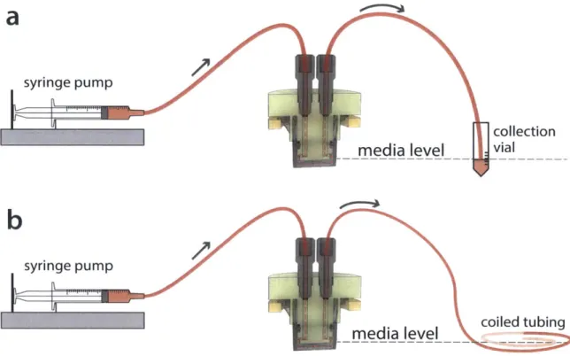
Figure 2-6 illustrates two possible setups of the entire apical flow system. Because a vast majority of the system is fully sealed, there is one primary variable that deter-mines hydrostatic pressure: height of the media at the outlet relative to the cell layer. Because the effects of hydrostatic pressure on these cells is unknown, it is desirable to maintain the media height at the outlet close to the height of the cell layer. Figure 2-6(a) is simple to set up and straightforward to collect media samples from; however, hydrostatic pressure will slowly build up as media height in the collection vial rises over time. In contrast, Figure 2-6(b) maintains a constant hydrostatic pressure, but retrieving media samples will require extra work from the user as the entire volume of sampling media is contained in a long coiled tube. It is worth noting that the setup in
syringe pump
media level
b
syringe pump
media level
coiled tubingFigure 2-6: Schematic of entire apical flow systei. Two possible setups that iniinize hydrostatic pressure on the cell layer are shown: (a) Outlet goes into a collection vial. where inedia level in the vial is at or near the height of the cell layer in the Transwell. (b) Outlet tulbiing is a long section of tubing that coils at the saine height as the cell layer.
Figure 2-6(b) has the additional benefit of sainple segregation bY time: older samples will be more d(ownlstream ill the tulbe, while newer sallples will be ujpstreal.
2.4
Apical Flow Insert Requirements
There are several requliremllents that must be considered in the course of desigiling the insert. In addition to standard inechancal considerations such as machining toler-ances. fit. and designing for simple user lan(lilig. there are biological considerations
to keep in llild as this device will be used to maintain a live cell culture. These requireIllelts will be discussed in this section. then srinnarized ill a reqluliremIents
tablle at the en(d.
a
'p
collectionI
.200 mm .200 min full t Maximum corne radius .00 0.21 X 90-+ Chamfer 10 - 32 UNF 2B imum hread .2 r 3 60Seaing surface flat to within .002
Figsure 2-7: Design guidelines for a fHat-bottomed port intended to interface to a 10-32 fitting with
a fHat-bottom ferrule. Note the callouts for a 32 microinch RMS surface finish and flatness on the bottoi surface of the port to ensure a robust seal between the port and ferrule. Dimensions are in inches. Illustration adapted froin a drawing rna(le available by Upchurch Scientific [14].
2.4.1
Mechanical Considerations
Fabrication Tolerances
A typical inachiiiinig toleraiiee for iniost diieiinsiois is 0.005". o al)ot
+125111
fromthe iioiiiinal diilensioll it is not i11coi111flon1 to see a dirawilig block within a tecineal drawing speifyilng a *defaiilt- tolerance of 0.005". and in fact many macline shops ale (apable of achieving higher l)re(isioln dliiriiig sta11dar(d operation vithout loss of
milanufactnring speed. Nonetheless. designing fotr a general toleranl(e of 0.005" is a safe approach, and calloilts for higlher precision im (ertaill critical featnres cami be
s)ecifie(d as lleeie(d.
One such ('alloilt is detailed in Figure 2-7. which illustrates designi guidelimtes for
fitting, ill turn. allows rigid tbing to connect to the apical flow insert for media repleiishmilent . To prevenit leaks. thc fitting essentially applies a constant dowiiward force on a flat-bottomed ferrule as it is screwed in., and the ferrule seals against the l)ottoiii surface of time port. Therefore, a sufficient "smoothness nuist be specified on
the bottoim surface to ensure sealing against a reasonable )pressure (generally oii the order of 100+ PSI). Figure 2-7 specifies this smootlness through two callouits at the
l)ottomH of the port specifying a 32 microiich R MS surface finish and flatness within
0.002".
40-V740
1200
Figure 2-8: Rotational constraints during and after asseinbly. The first two renders in this series illustrate the location of the cross-sectional cut to better understand the context of the third render. The third renlder highlights the 120 rotational synnnetry of the apical insert as well as the 4' buffler for rotational error between the Traniswell aiid apical insert.
Design for Assembly (DFA)
Coupling the apical flow insert to a 12-well Transwell innst be done by the user. so increase(l effort must lbe extended in (esigiiug al iisert that asseibles with a Traiiswell easily with iiminimal room for assemiiilv error.
The apical flow coipoieits have several features to assist with assembly. The ID
of time lower ring, which is the first coimpoiieiit to le placed during assembly. is very
close to the ID of a well froiii a 12-well pllate. This allows the user to take advaitage
Transwell on the lower ring.
The apical insert, Transwell, and lower ring are translationally fixed relative to each other once assembled-in other words, if one component is translated in space, the other two components are translated with it by the same magnitude. However, in some designs it is possible that the components are not rotationally fixed to each other. Since the apical insert is fastened to the lower ring and not directly to the Transwell, the Transwell could technically slip and rotate about its centerline independently of the insert/ring, which would be undesirable. Therefore, a feature has been designed into the apical insert to fix all three components rotationally, as seen by the three green radial protrusions in Figure 2-8. The feature utilizes the three flange supports on the Transwell-or specifically, the gaps between them-to constrain rotation of the Transwell. If the Transwell does slip from the insert/ring, it can only rotate 4' before one of the flange supports collides with the apical insert. This feature, which is rotationally symmetric of order 3, allows for three possible ways to place the insert into the Transwell. If the user initially misplaces the insert, they could simply rotate it in either direction until the insert feature lines up with the gaps between the Transwell flange supports. In the absolute worst case, the user would have to rotate by 56' before the insert falls into place.
2.4.2
Biological Considerations
As this is a component that will be used in conjunction with a live cell culture, there are several biological constraints that must be considered in the design. For example, any materials used with the insert must be biocompatible and ideally low in protein adsorption, as the user should be able to use media with a known concentration of supplements without concern for losing a significant amount of their reagents to sur-face partitioning. In addition to material choice, the volume of media (and therefore, total amount of available nutrients) supported by the insert is highly applicable to
cell viability, and there are certain critical dimensions to the insert that directly affect total apical media volume.
Material Choices
There are several material considerations involved in designing a device to be used in tandem with cell cultures. Any device that interacts with cultures must be sterilizable to minimize risk of contamination. This sterilization is commonly done through autoclaving, where components to be sterilized are placed in a chamber that undergoes cycles of high heat and pressure to kill a majority of potential contaminants. There also exist other sterilization methods for components that cannot withstand the high temperatures and pressure of an autoclave, such as ETO sterilization and gamma ray irradiation. However, these methods tend to be more time consuming for biologists, as autoclaves are by far the most common (and typically the most convenient) form of sterilization. Thus, it is beneficial to choose materials that can survive the autoclaving process.
Polysulfone, a thermoplastic that is fairly machinable and autoclavable, has been used in cell culturing devices such as the previously developed LiverChip [15]. There-fore, there is precedence in using polysulfone for the apical flow insert as there exists a body of knowledge to build upon. Generally, polysulfone surfaces that will come in contact with culture media are first passivated by submerging or priming the re-spective surfaces with media, so the apical insert must be amenable to a passivating procedure that is easy for the user. Potential approaches involve partially submerging the insert in media in a 6-well multiwell plate while continually priming any internal channels with media.
Media Volumes and Replenishment Rates
Apical and basal volumes were determined based on considerations in media replen-ishment. For this in vitro model (and generally for many static Transwell cultures), media is manually replaced every 2-3 days to replenish media nutrients that have been depleted by the culture. This manual media replacement rate is generally found experimentally, and depends on both the culture's consumption rate and the volume of media used. In the case of fast consumption and/or low volumes, media replace-ment must be more frequent, and correspondingly less frequent in the opposite case of slower consumption and large media volumes.
The volume in the apical chamber is primarily determined by how far the insert protrudes into the Transwell, and can be characterized by a height h between the Transwell membrane and the bottom of the apical insert. Given a membrane surface area of 112 mm2, a height of h = 2 mm was chosen to create an apical volume of 224 pL. Thus, if a flow rate of 0.51 day is used, the apical media will be completely replaced twice a day. Though this may seem aggressive, this value was chosen to mimic a protocol developed in our lab consisting of half-volume media replacement every 6 hours on the static microbiome co-culture, as certain microbe strains have the potential to quickly proliferate and dominate the culture.
2.4.3
Design Parameter Reduction
With many points to consider both on the mechanical and biological side, it is helpful to create a table of relevant parameters to guide design and operation. Table 2.1 shows such a table for the apical flow insert, with variable names defined for each parameter, a list of dependencies (if any), a desired range of values for each parameter, and justifications for each range. In an effort toward dimensional reduction, parameters are distinguished by those that are "driving," or explicitly determined by the user or
designer, and those that are "driven," or implicitly determined via relations to sets of driving parameters. With these parameter values in mind, a more informed design can be created.
Table 2.1: DESIGN AND OPERATION PARAMETERS
Parameter Name Dependencies Priority Desired Justification/Notes Range
Culture . . 100-200 e 12-well transwell is 112
Surface Area A Driving mm2 mm2 as a starting point e Scaling recommendation is to maximize surface area
Apical e <1mm may cause issues
Channel h Driving 1-5 mm with priming, general
Height operation
a "Tall" channels (5mm or more) can create large 02 gradients, possibly capable of housing both obligate
anaerobes and microaerobes Apical
Volume Vtop A, h Driven 100-500 pL Calculated from A, h
* Current basal volume is
1.5 mL
Basal . . 500-1000 e Scaling recommendation is
Volume DiL to minimize basal volume
* 500 pL is a potential minimum for nutrient delivery
Apical Flow Wide range due to
A ae Flow Vtop, nutrient . 100-1000 uncertainty-experimental
Rate QiDriven
(volumetric) requirements iL d- 1 validation may be best approach to narrow range
Highly
Apical Flow Dr dependent Useful to consider for wall Rate (linear) U' A riven on inlet shear stress
geometry
Apical Defined as Q!2R. One of the
Dilution D Qtop, Vop Driven 1-5 d- 1 key characteristics of a
Rate chemostat; helpful for
planning microbe dilution * 160
mm0g e 160 mmHg is ambient P02
mmHg
Oxygen 9 30-40 * 30-40 mmHg is in vivo
Tension of P02 Driving H P02 throughout all three
Feed sections of small intestine
* 0.05 e 0.05 mmHg is -75 ppm
mmHg (anaerobic chamber) Table of parameters to guide design and operation of apical insert. Parameters are distinguished
by those that are "driving," explicitly determined by the user or designer, and "driven," those that
14 0 .260 FLAT BOT f, i 10-32 UNF 20 0 0 0 138 0.1 2 0.269 0o149 0) -DCo 0 87 0.269 0.6 12 0.907 0 C 0.063 coi SECTION A-A 02 C C) ,j DETAIL C SCALE 4: 1 0/4 K b DETAIL D SCALE 4: 1 c 0 0 TITLE:
12-WELL ATTACHMENT BASE
UNLESS OTHERWISE SPKE-)ED
HREE PLACE LDEC IMAL -0.0 W
cu-"6LYSULFONE SIZE DWG. NO.
B
REV I
SCALE: 2:1 WEIGHT: SHEET 1 OF I D 0 321-/ DETAIL B SCALE 10 : 1 cv) b0 -4 bC 02' i
Chapter 3
Computational Models of Fluid
Dynamics, Oxygen Transport and
Reaction, and Heat Transfer
As discussed in Section 1.1, there exists a steep radial oxygen gradient within the small intestine, from the oxygenated submucosa to the nearly anoxic lumen. In an effort to recapitulate this phenomenon in vitro, a major design goal for the apical flow insert is the capability to control apical oxygen tension. There are many factors that affect oxygen tension within the system: the enterocyte and goblet cell coculture on the Transwell membrane will consume oxygen, and in a microbiome culture any aerobic microbes suspended in the apical chamber will consume oxygen as well. These microbes will also proliferate as long as there exists a sufficient nutrient supply, which in turn further increases the total oxygen consumption rate. To balance this removal of oxygen from the system, oxygenated media can be introduced through the apical or basal inlets, and the act of flowing new media through the apical channel may also reduce the population of oxygen-consuming microbes as suspended microbes are
washed away.
As this is a fairly complex environment, it is helpful to model this system to gain insight into the relationship between parameters such as apical and basal flow rate, unknowns such as growth rate and oxygen consumption rate for the microbe strains of interest, and the resulting oxygen gradients within the system from these parameters and unknowns. In this chapter, we present a first step toward this complex oxygen model, beginning with models of computational fluid dynamics to understand velocity profiles through the device, as well as an oxygen transport and reaction model incorporating the cell coculture (without microbes) to gain insight into what oxygen gradients are achievable within the device when only mammalian cells are present. Additionally, we present a heat transfer model to determine whether the warm air of the incubator is sufficient to warm up room temperature media before it comes in contact with the culture. All finite element models presented here were created and simulated in COMSOL (4.3a, COMSOL Inc., Burlington, MA).
Before presenting the models, we begin with a discussion of the geometry used for these finite element models, as there are characteristics that can be simplified for the purpose of optimizing model run time.
3.1
Model Geometry
To model characteristics of flow, oxygen transport, and oxygen consumption through the system, we wish to model the assembled apical insert and Transwell as presented in Figure 2-4. However, though it may be possible to directly import the geometry of the apical flow insert as designed and create finite element models based on that geometry, it is more efficient in the long run to consider what simplifications can be done while maintaining a realistic representation of the geometry of interest.
domain 1 apical chamber domain 2 celL/membrane layer domain 3 basal chamber
Figure 3-1: Exploded view of geonietry used for flow and oxygen transport nollels. The geonietry is split into 3 domains: the apical chamnber, the cell/ineiibrane iyer, and the basal chamber.
apical insert. The inlet and outlet have a fairly high aspect ratio -the inlets are
approximately 1/2" in length. kit a notable portion of the inlet diameter is 1/16".
It is reasonable to assunie that media flowing through the inlet an(l outlet will reach fully developed flow well before it travels the entire 1/2" length. This -length to
fully developed flow." or Cntrnucc itth. is defined by L, = 0.05 - Re - D. where Re
is the Reynolds number and D is the diaineter of the inlet. Using D = 1.59nn
and(1 a calculated Reynolds mumbler of Re = 0.005. we find L, ~ 41m. an extremely
short entrance length duc to a slow volumetric flow rate of 500iL d-1. Thus. before
any ieanigful modeling is done, we can already assume that the long inlets are
not necessary for nodeling purposes and can be drastically shortened in the model
(though they do serve the functional purpose of guiding media from tubing to the
apical side of the Transwell).
Another area to coisiler is the cell monolayer on the Trainswell membrane. as
will be consumed as it diffuses from media through the cell layer, and the thickness of this cell layer affects total consumption. Additionally, the cell layer itself ideally models the barrier between the intestinal lumen (the apical side) and the basolateral membrane/circulatory system (the basal side), and its efficacy at barrier function in turn affects the permeability of larger molecules such as diclofenac or various lipopolysaccharides. To simplify the complex geometry in this area, the cell layer and membrane are modeled as a single 50 pm thick disc that separates the apical and basal domains, based on the thickness of the Transwell membrane and the approximate height of Caco-2 cells, which are columnar epithelial cells.
With these considerations in mind, we create the model geometry seen in Figure 3-1. For modeling purposes, the entire geometry is split into three domains; the apical and basal chambers both represent the regions where media can flow, while the cell/membrane layer represents the cell coculture and Transwell membrane.
3.2
Flow Modeling
As one of the core features of this device is that it allows for apical flow in a Transwell, one pertinent question is how exactly the flow behaves in the device. To create a more controlled environment, the inlets to the apical chamber must be designed such that flow is fairly even across the Transwell, which in turn allows for an even distribution of fresh media across the cells. In this section, two designs for the apical insert inlets are presented and their respective velocity profiles in the apical chamber are modeled.
3.2.1
Setup
In this model, the apical domain is the only domain studied as our main interest here is the velocity profiles of media in the region directly above the cells. The governing
equation for fluid flow in this system is the Navier-Stokes equation [16]:
p +(- V)) = -VP + V2 . (3.1)
Ot
Here, p is fluid density, p is fluid viscosity, and VP is the pressure gradient. In practice, the system will likely be run at a constant flow rate, and in the absence of turbulence or any elements that create oscillatory flow, we can assume steady-state flow. Specifically, this means there is no local acceleration of fluid, but convective acceleration can occur due to changes in geometry as fluid travels through the system:
oca convective
However, this can be further simplified. For example, explicitly writing the con-vective acceleration term and the viscous term in the x-direction gives:
p U- +V
(O
Ou + On =- VP+p _ (92U +I 02U +. &2UO y OY z OX Oy2 OX2
(a) (b)
We perform a scaling analysis on terms (a) and (b), defining a characteristic length
L for
A:
2
puL ?
~L 1. (3.2) P
The left side of Equation 3.2 is the Reynolds number, the ratio of inertial forces to viscous forces. If the Reynolds number is close to 1, both forces are comparable and neither may be neglected.
When we consider practical usage of the apical insert, volumetric flow rates (and therefore velocities) will be very slow to maintain steady, constant media replen-ishment during operation. The suggested flow rate mentioned in Section 2.4.2 is 500pL d-1, which can result in a linear velocity on the order of nm s-1. This results in a very low Reynolds number, which suggests that viscous forces dominate in this system during normal operation; inertial forces can be neglected. Similar scaling ar-guments can be made in the y- and z-direction, reducing the Navier-Stokes Equation seen in Equation 3.1 to the simpler Stokes Equation:
0 = -VP + PV2-V. (3.3)
Therefore, with the simplifications explained in this section thus far, we are justified in using Equation 3.3 as the governing equation for the finite element models of flow that are conducted throughout this chapter.
3.2.2
Inlet and Boundary Conditions
Conditions for the finite element model are seen in Figure 3-2. As previously
men-tioned, the apical chamber is the only geometry considered for this particular model, so this system is notably easier to work with. As the apical chamber is fully enclosed, a no-slip condition (i.e. a wall) is defined on all surfaces other than the inlet and outlet. For simplicity, media is modeled as water, using the viscosity and density of water. Values used for the various parameters in this model are seen in Table 3.1.
In an effort to create a more even velocity profile directly above the Transwell membrane, two different geometries are modeled with these conditions. The first geometry, based on the first apical insert design that was created, is seen on the left side of Figure 3-3. If we imagine a fluid particle traveling through this volume from the inlet to the apical chamber, there are some domains that we can define-there is'
apicaL inLet
apical outlet a = 5.79 nL/s (-500 pL/day) P 0
media modeled as water: p,p
no-sip condition on all other surfaces
Figure 3-2: Conditions for modeling flow in the apical chaniber (doimain 1 in Figure 3-1). The
surfaces in this figure are the boundaries of fluid flow. A voluinetric flow rate is set at the inlet and a stanldard 0 PSIG (i.e. no head pressure) condition is set at the outlet. Other thani the inlet and
outlet, all surfaces in the apical doinain are no-slip surfaces.
the vertical cylindrical channel that foris the inlet, followed by a horizontal channel.
then a vertical curve(I slot that connects the horizontal channel to the apical chliiber.
The purpose of the curved slot is to spread out the velocity profile. as fluid exiting the
liorizontal cliainiel will iitially be concentrated around its cylindrical shape. Thus,
the vertical curved slot essentially creates rooin or noinentuin diffusion to occur.
ideally creating a more even velocity profile by the tine the fiuid reaches the apical
chanilber.
The second geometry to be ilodteled can be seen on the right side of Figure 3-3.
This geometry is similar to the first geonetry with one key difference: rather than a
horizontal bore to connect the inlet to the vertical curved slot, the second geometry
uses a wi(le slot to connect the two domains. From the perspective of the fluid, the vertical inlet connects to a half-circle perpendicular to the inlet itself, thus allowing
Table 3.1: PARAIrETERs FOR MOOELING MliDIA FL Ow
Parainieter Description Value Used iii Model t(2) Voluinet ric apical flow 5.79 iiL
s-rate
p Density of water 1000 kg
nin-/1 Viscosity of water 8.90 . 10- Pa s Table of values llsed to nillodel niledia flow througli the apical insert.
inlets horizontaL bore vertical slots apical channel
horizontaL
sLot
Iit
Fignre 3-3: Illustrations of different geollietries of the apical flow doiiain. The geonetry on the left
has a simple horizontal bore connecting the inlet to the vertical slot, while the geonietrv oil the right
utilizes a horizontal slot instead, further spreading out flow.
will be further explored in Section 3.2.3.
3.2.3
Results
Results fron the flow 111(( givel the lpreviolsly defined geometries and paralieters are seen in Figures 3-4 and 3-5, for the straight horizontal and slotted horizontal
cianllels respectively.
Subfigures 3-41) and 3-4c present a colormap visualization of the velocity pjrofiles in the apical chanlber. The curved vertical slot does influence flow spreading to some
degree if the c(onnections to the vertical inlets were simply cylindrical (hannels. we
would see a velocity profile that more closely follows the shape of a paraboloid in
the apical chamber. Although these subfignres can be very elucidating at a glance.